Week 6 - CHT Analysis on a Graphics card
- Aim:To Perform a steady-state conjugate heat transfer analysis on a model of a graphics card.
- Objectives:
- Run the simulation by varying the velocity from 1m/sec to 5m/sec for at least 3 velocities and discuss the results.
- Find out the maximum temperature and heat transfer coefficient attained by the processor.
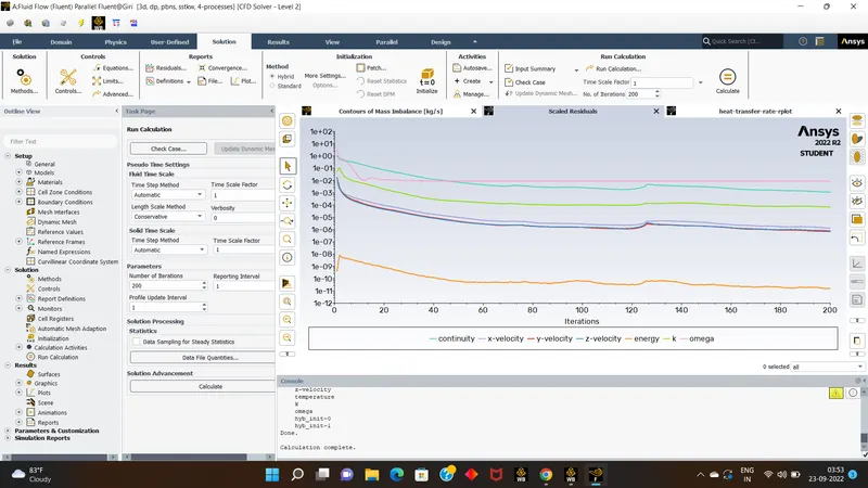
- Prove that the simulation has achieved convergence with appropriate images and plots.
- Identify potential hotspots on the model.
- Introduction/Theory:
We will conduct the Conjugate Heat transfer Analysis over the Graphics card, which contains Base,Fins,Processor, With the power of 54W, And dimenssions of processor is 8*8*1 mm^3. Here the processor will be the only one which producess heat,Fins are used to desipate the heat produced by the processor.
- Solving & Modelling approach:
- First we will download the graphics card over the geometric workbench, than we will select the whole geometry & procced with share prep option from workbench tools, so share topology will be enabled.
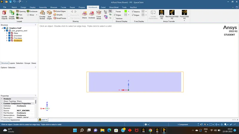
- now close the geometry & open mesh.
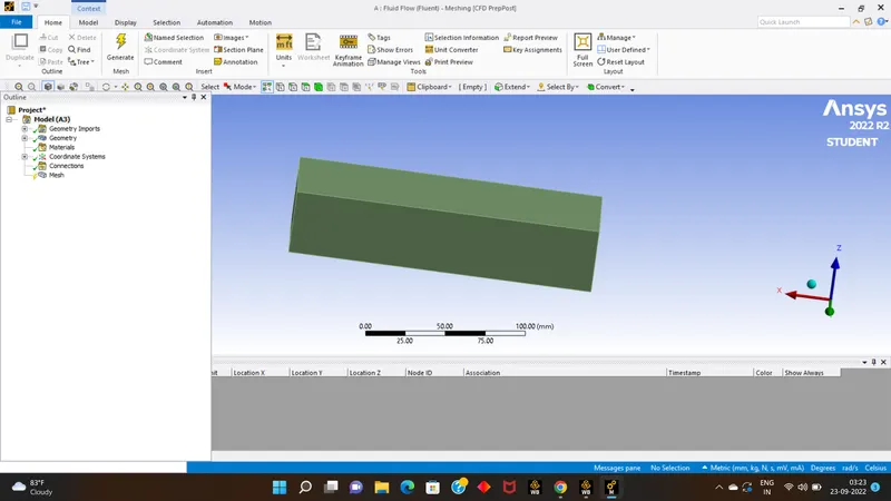
- now name the surface with their respective names by selecting faces/body & shortcut key N.
- than generate mesh ove the model with default element length.
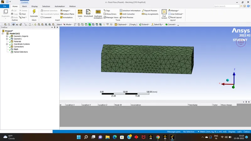
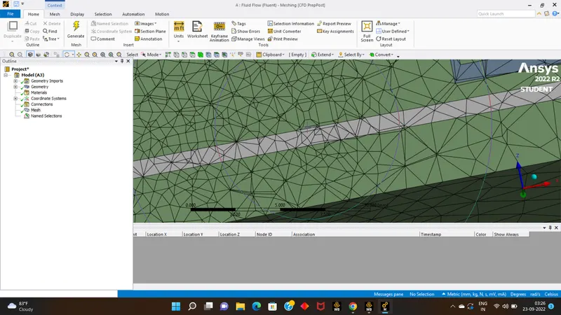
- than close the mesh & open setup part.
- Pre-processing and solver setting:
- Run the setup part with double precession with 4 processor.
- Simulation Setup:
1- solver: steady state
2- Type: Pressure Based
3- Turbulance Mode : k-Omega SST
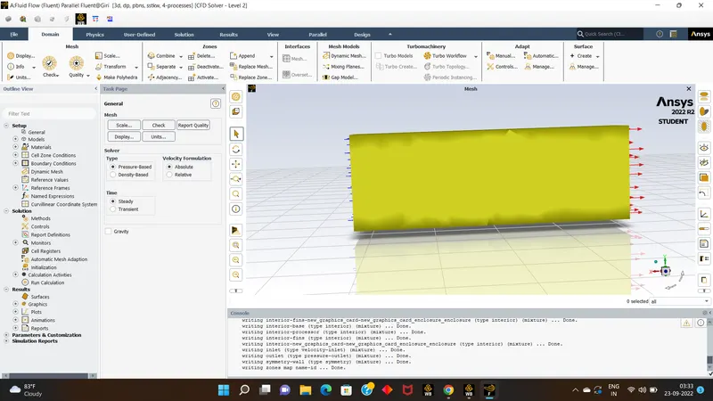
- Than go to the material selections.
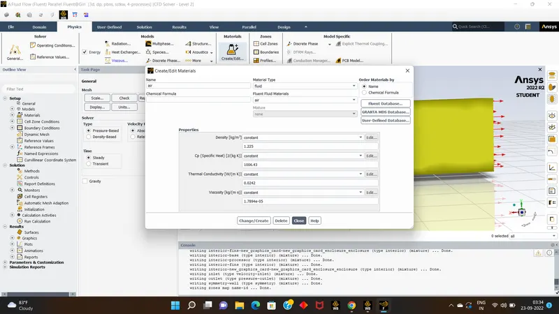
- Materials Choosed :Fins -alluminium,Base-Plastic,Processor - Silica.
- Than Go for cell zones and assign for respective material.
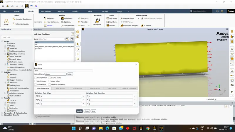
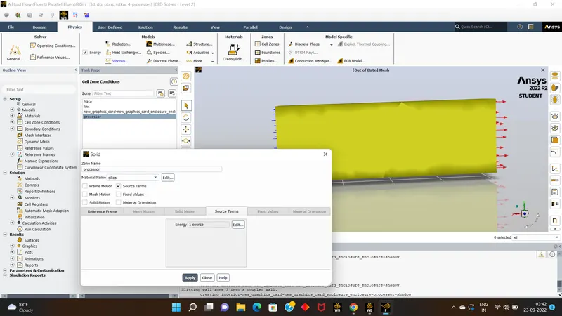
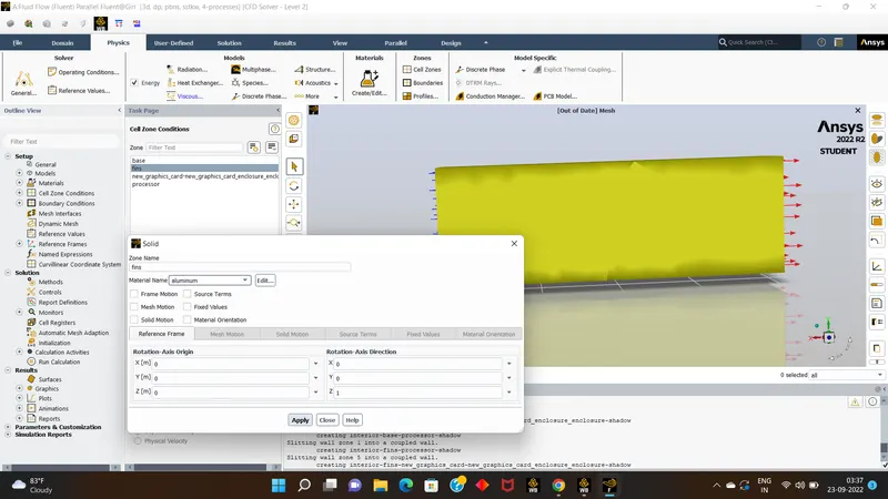
- after ssigning cell zones,go to boundries.
- in boundries set the inlet velocity as 1 m/sec
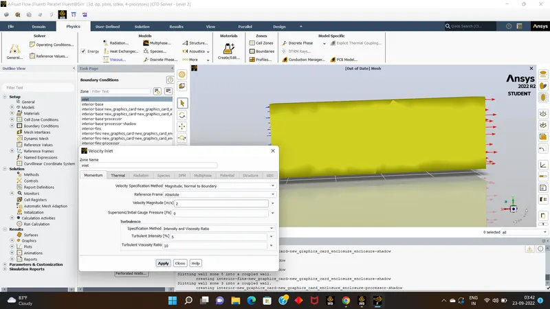
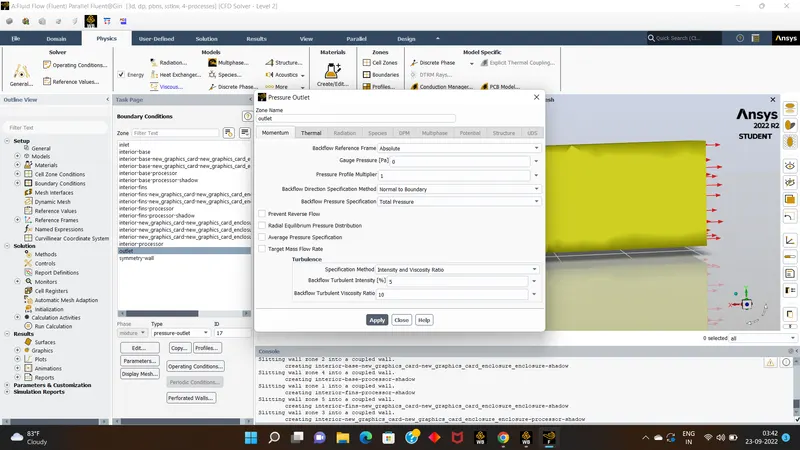
- for outlet it will be 0.
- Than go for solution part initalise it.
- than jump to next results part, create the required contours such as maximum temperature , Heat transfer coefficient,Residuals.
- than run the calculations for 200 itterations, wait for the plots to be obtained.
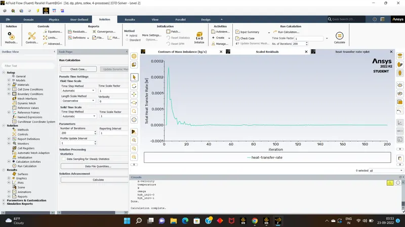
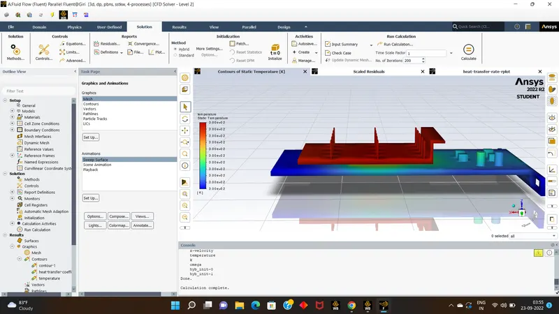
- Results:
- In results parts we will see the temperature flow through processor by fins, base .
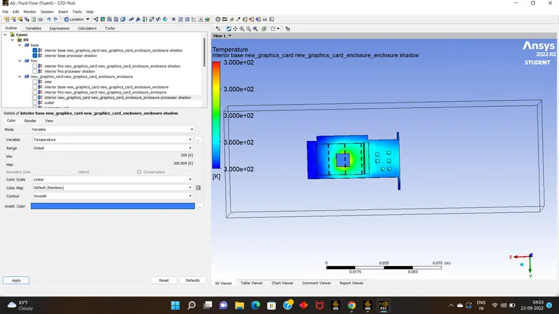
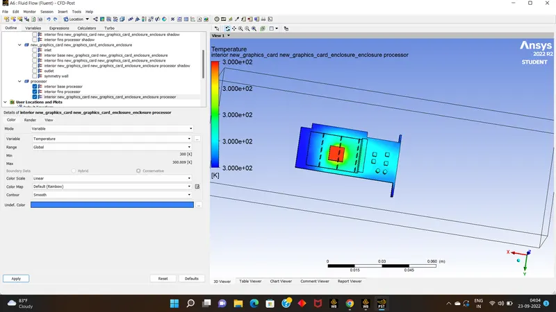
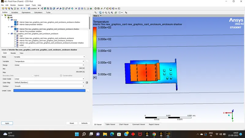
- we can see the temperature is at peak or potentail hotspots are observed at the processor,becz the more heat is produced by processor itself.
- now we will check the same simulation by varying inlet velocity from 1 to 5 with any 3 velocities,& we will also refine the mesh quality.
- Refined meshquality by : 5mm
- inlet velocity : 2 m/s
- The results obtained in this was like:
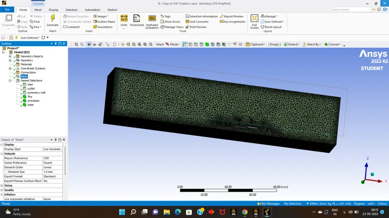
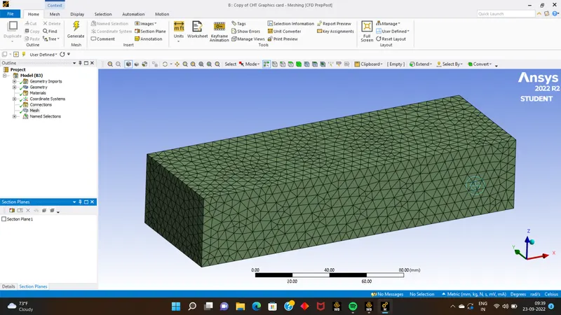
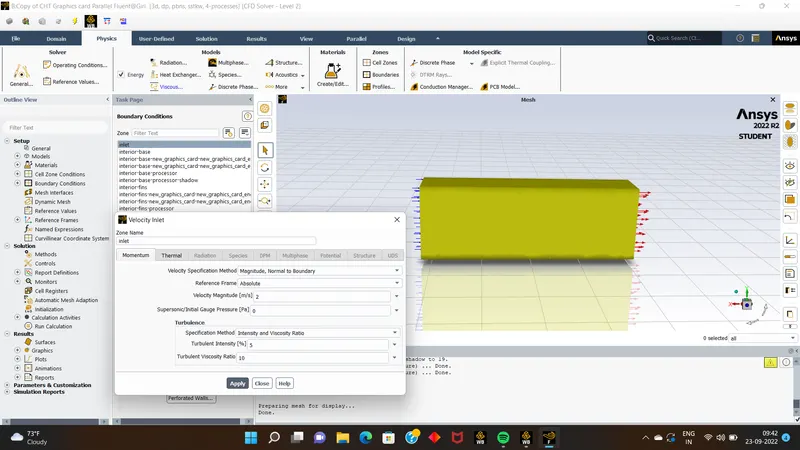
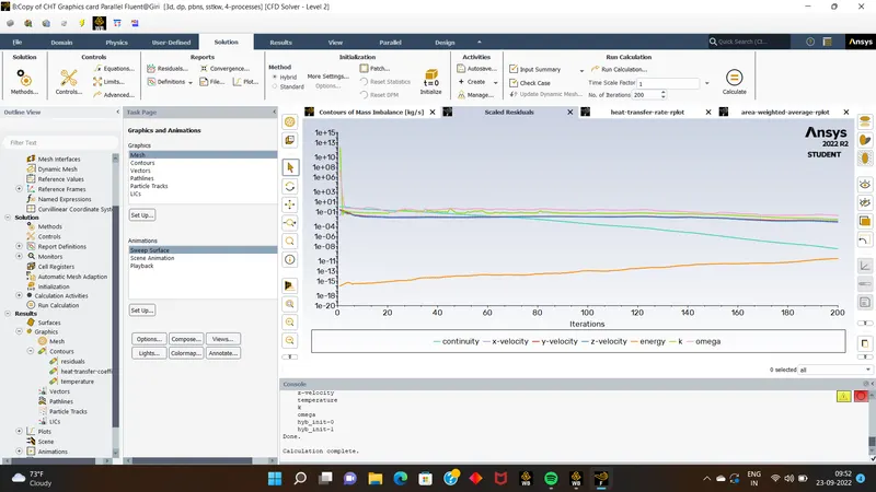
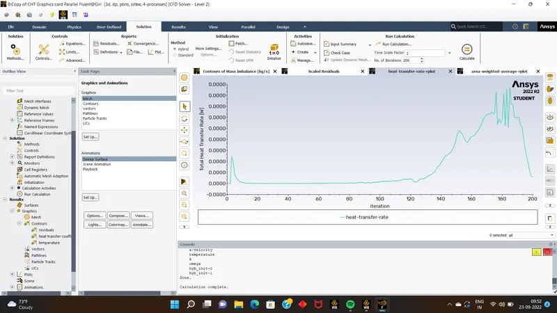
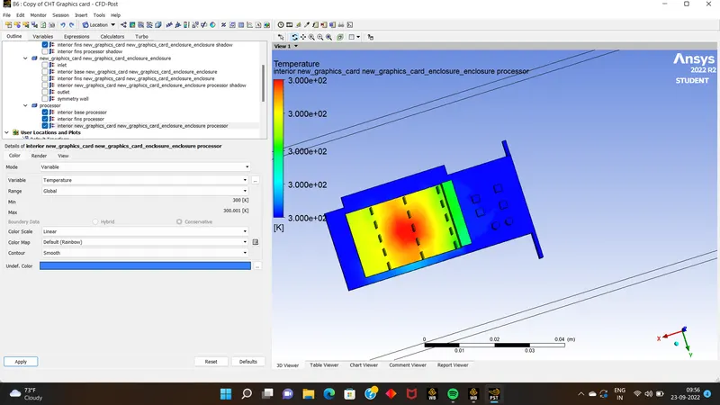
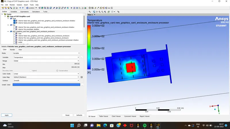
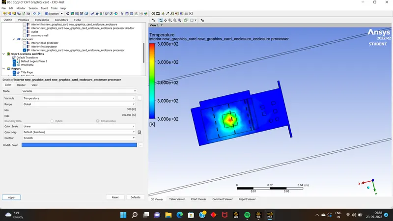
- conclusion for this is as compered to unrefined mesh the heat despiated wa less than compared to previous one ,it was better than previous one.
- here also source of heat was processor only.
- but the residuials were not convergent.becz for convergence the resediual should be continius & velocity should be less.
- now we will also check it by varying the inlet velocity for 4 & 5 m/s.
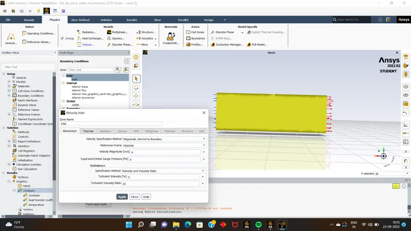
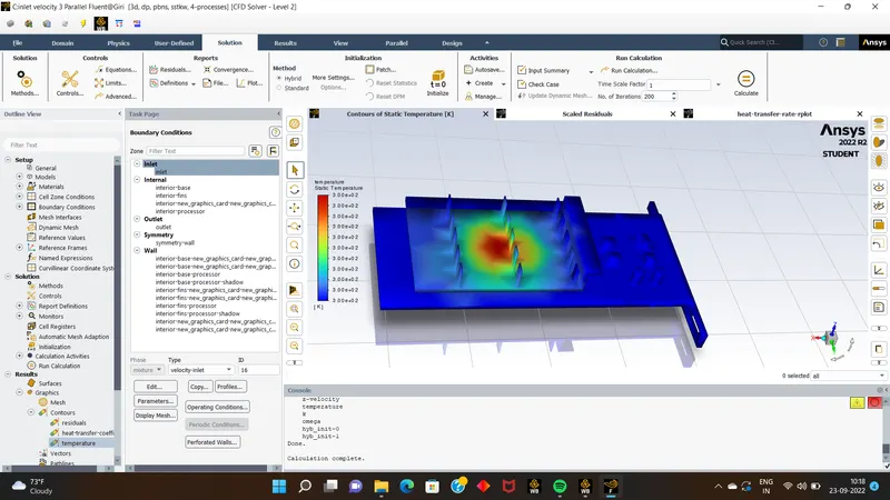
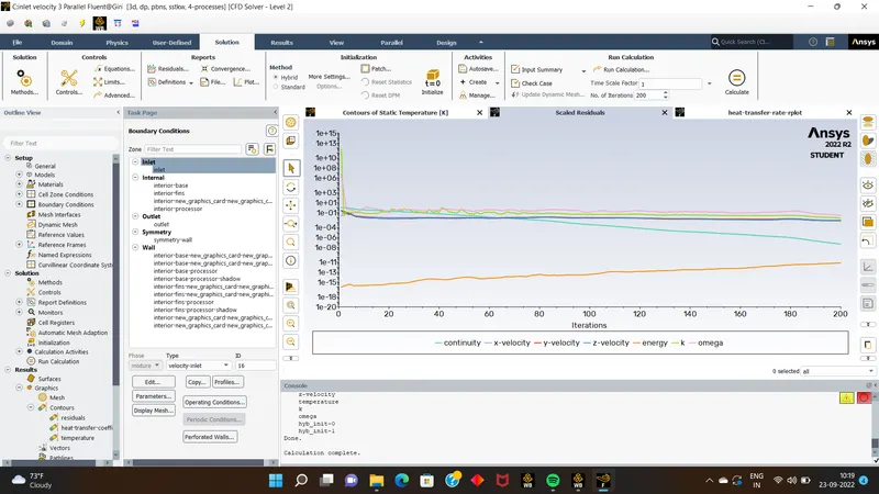
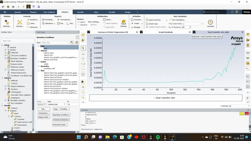
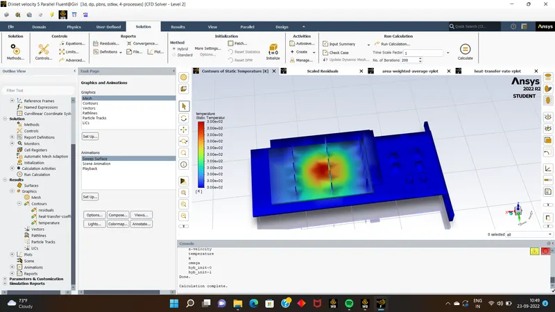
- these were the heat or temperature despitated over the surface of graphics card .
- Conclusion:
- by the varying the inputs & meshing over the graphics card for the same simulation we can see different results, by seeing that we can conclude tht when the meshing is not refined the heat disepeated over the graphics card is more than the refined mesh .
- simillarly on increasing the input velocity over the graphics card through enclousre the heat flow over the surfaces of graphics card will reduced as velcity increases.