Week 6 - CHT Analysis on a Graphics card
`************` CONJUGATE HEAT TRANSFER OH GRAPHICS CARD `************`
- AIM -
To perform the steady-state conjugate heat transfer analysis on the graphics card model by choosing the appropriate material.
- INTRODUCTION -
Conjugate means coupled connected or related. Heat is defined as energy transferred by virtue of temperature difference. It is customary to refer to different types of heat transfer mechanism modes. In general, heat transfer describes the flow of heat (thermal energy) due to temperature differences and the subsequent temperature distribution and changes. The study of the transport phenomenon concerns the exchange of momentum energy and mass in the form of conduction, convection, and radiation. The term conjugate heat transfer analysis type allows for the simulation of heat transfer between solid and fluid domains by exchanging thermal energy at the interfaces between them. In solids conduction often dominates whereas, in fluids, convection usually dominates. Conjugate heat transfer is observed in many situations. For example, forced convection heat transfer through heat exchangers, various electronic equipment, in recent times data centers, small electronic equipment, condensers of various refrigerating equipment, automobile engines, etc. Conjugate heat transfer main integrated part of surface heat transfer between solid and fluid or solid-solid.
Conjugate heat transfer analysis of graphics card model is carried out to identify the heat transfer capability through fins and to select the proper material for the graphics card. To carry out the mesh independency test and select a suitable mesh size for the analysis and later on analyze three cases to find out the changes in heat transfer from the fins by varying the velocity of air.
- GEOMETRY -
The graphics card consists of three components base, the processor, and fins. To assign proper material the different manufacturers use the different material according to design and availability so for this case following materials used.
Table No. 1 Material Properties.
| STEEL | SILICON | ALUMINIUM | |
| DENSITY (Kg/m^3) | 8030 | 2330 | 2719 |
| SPECIFIC HEAT (J/KJ-k) | 502.48 | 710 | 871 |
| THERMAL CONDUCTIVITY (W/mk) | 16.27 | 150 | 202.4 |
| COMPONENTS | Base | Processor | Fins |
The material used for the processor is user-defined based on the properties of silicon.
In this case, the commercially available 4 GB GTx 1050 Ti 4GT of MSI brand Gforce is assumed for the analysis for the calculation of heat generation and the assumption of the materials. The overall wight of the Graphics card is 998 g. The themal design power (TDP) generated through the processor is 75 W.
Heat generation in graphics card :
Heat generated (`W//m^3`) = `(TDP)/(V_P) = (75)/(64e-9) = 1171875000 (W/m^3)`
The Vp is the volume of the processor which is calculated as (8*8*1) = 64 mm.
- GRAPHICS CARD -
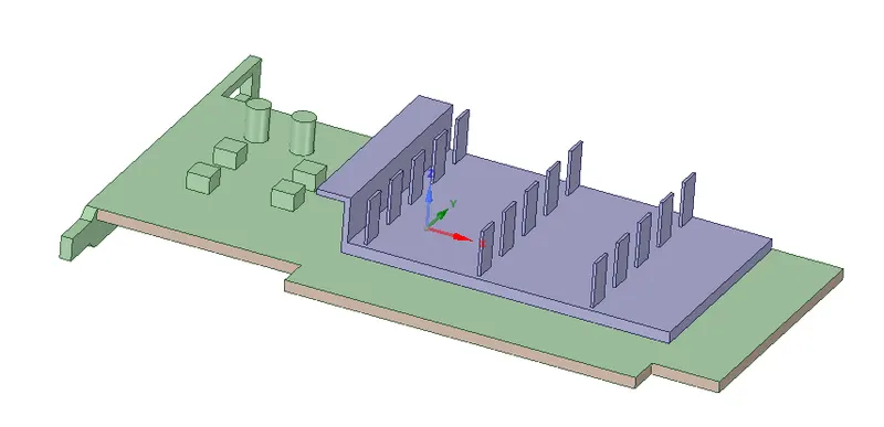
Fig No. 1 Graphics card.
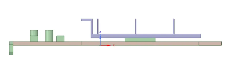
Fig No. 2. Side view of Graphics card.
- MESHING -
- CASE I - Baseline mesh
The curvature and proximities are enabled on the default setting to capture the small details near the processor and the fins area.
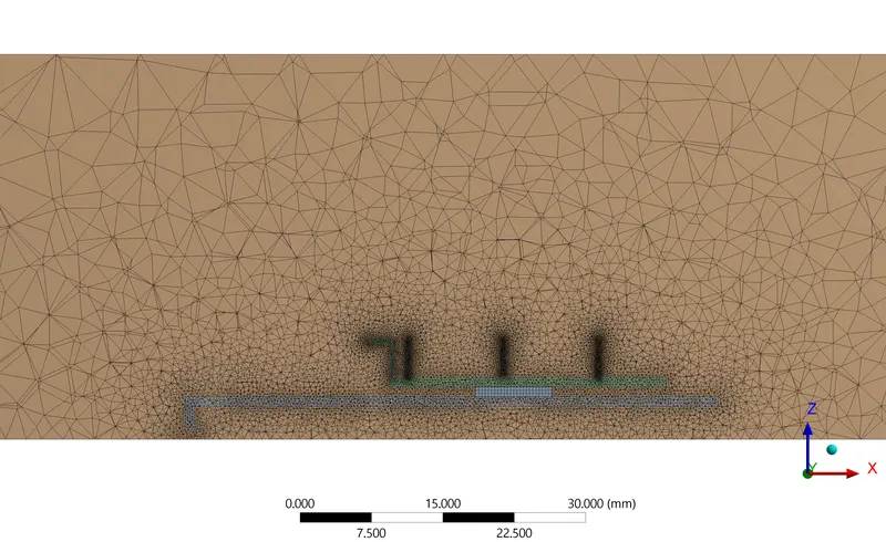
Fig No. 3. Baseline mesh cross sectional view.
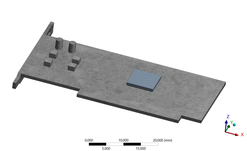
Fig No. 4. Baseline mesh base and processor.
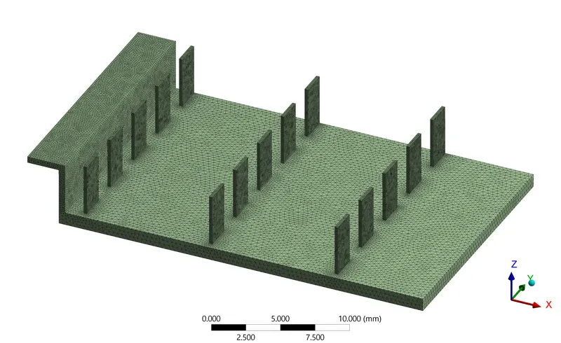
Fig No. 4. Fins mesh.
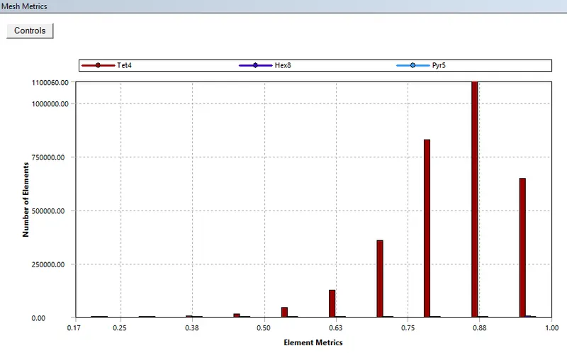
Fig No. 5. Mesh metrics for baseline.
- CASE II - Refined mesh
The following parameters in the settings changed to improve the mesh quality. The sizing parameter is used to fine the mesh because the tetrahedral mesh is automatically selected.
Table No. 2 Refined mesh sizing.
| ENCLOSURE | BASE | PROCESSOR | FINS | |
| SIZING | 5 mm | 0.5 mm | 0.05 mm | 0.5 mm |
| PROXIMITY | Yes (0.1 mm) | Yes (0.1 mm) | Yes (0.1 mm) | Yes (0.1 mm) |
| CURVATURE | Yes (0.1 mm) | Yes (0.1 mm) | Yes (0.1 mm) | Yes (0.1 mm) |
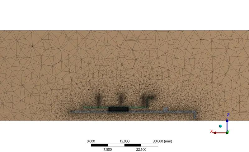
Fig No. 6. Refined mesh cross-sectional view.
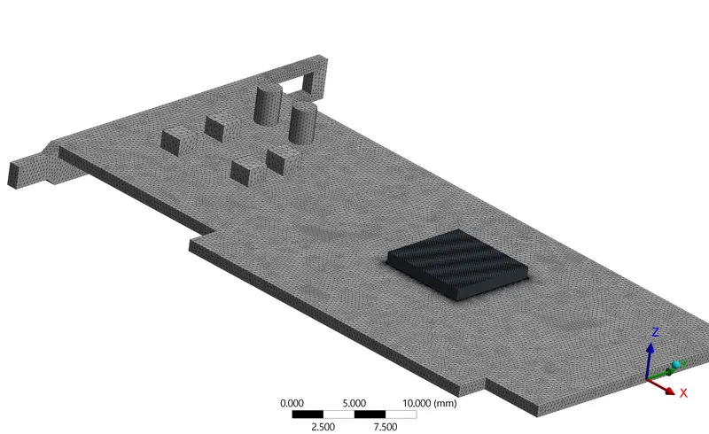
Fig No. 7. Refined mesh base and processer.
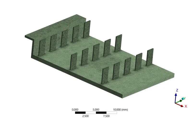
Fig No. 8. Fins mesh.
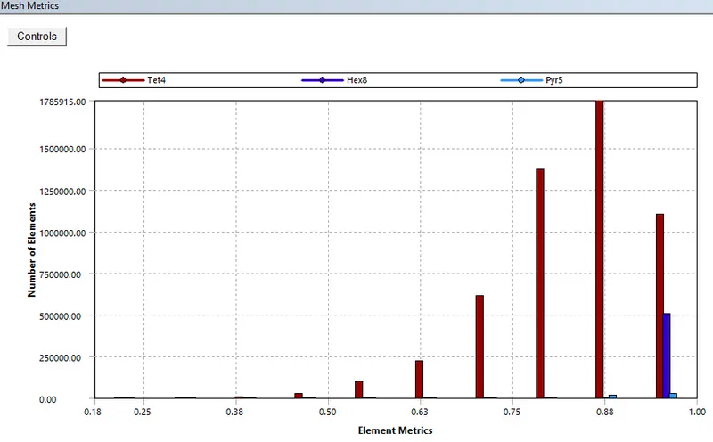
Fig No. 9. Mesh metrics.
From the above mesh metrics, the quality of the mesh is above 50% that indicates the quality of the mesh is maintained throughout the geometry. The above figures show that how well the geometry has been captured and the exact matching of the quality. The below table it indicating the number of nodes and elements comparatively it easier to know that the mesh is pretty fine. In shell conduction, if the mesh is not able to capture the outer surface and not able to transmit the data at the boundary then it is necessary to enable the shell conduction. Shell conduction is not necessary for this problem because the mesh quality is maintained enough to calculate the heat transfer away from the boundary.
Table No. 3 Mesh details
| Baseline mesh | Refined mesh | |
| Nodes | 546904 | 1445392 |
| Elements | 3108765 | 5752675 |
- SOLUTION -
- CASE I - BASELINE MESH
Boundary condition -
- Heat source at processor - 117187500 (W/m3)
- Inlet Velocity - 2 m/s.
- Air temperature - 300 k
Solution method -
The RNG k-e model with wall treatment and SST k-w model predicts the nusselt number distribution better than the other models for the flat plate as well as for the other concave surface impingement case. However, hydrodynamic data such as the mean velocity profiles are not accurately predicted by the SST k-w model for the concave surface impingement case, whereas the RNG k-e model predictions of the velocity profile agree very well with experiment data. The Reynold stress model does not show an advantage over other eddy viscosity models. The k-e realizable turbulence model used to solve this problem since the solution converges faster.
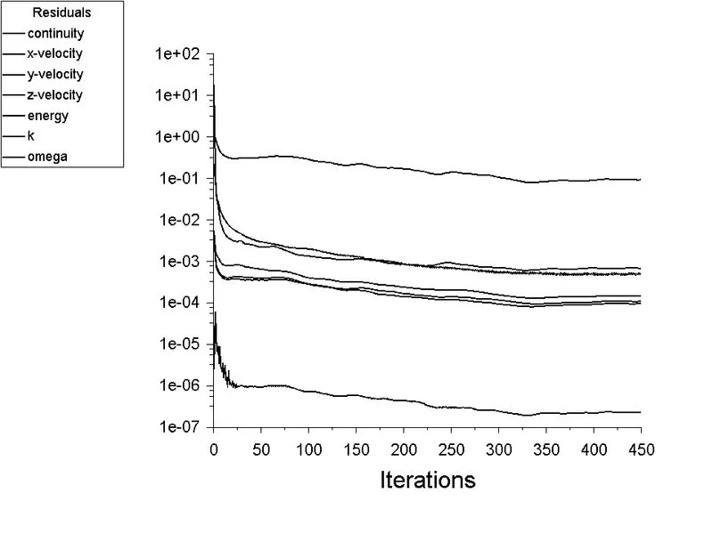
Fig No. 10. Residual plot.
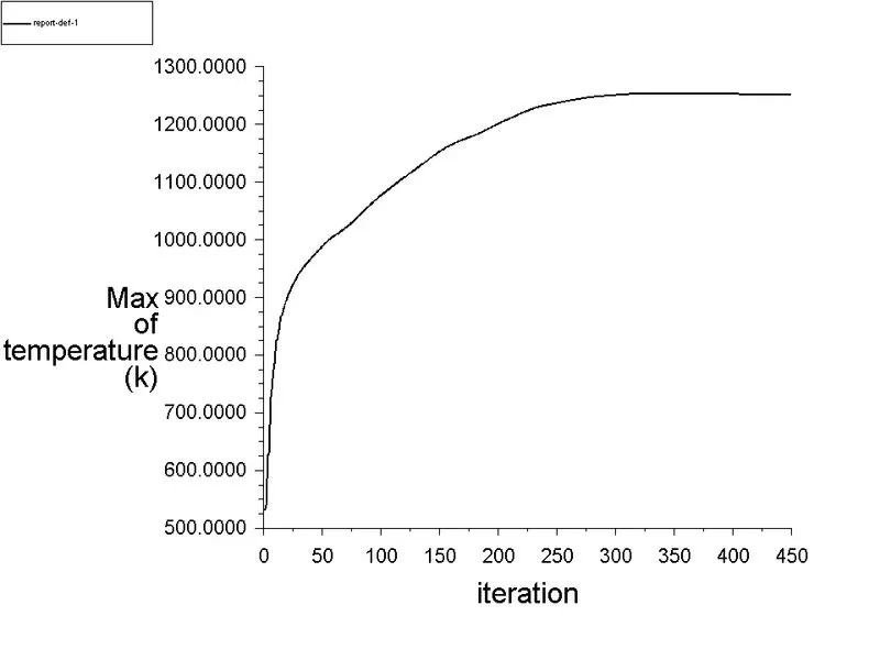
Fig No. 11. Maximum temperature of fins.
The convergence of the analysis always depends upon the different physical parameters. In our case, the convergence of the result depends upon steady-state heat transfer away from the fins because fins are used to increase the heat transfer rate to air through convection. The heat transfer will not be maximum unless the temperature of the fins reaches the steady-state and change in maximum temperature of the fins with respect to iterations is negligible. That's why the max temperature of the fin is important and needs to be maintained at a steady-state.
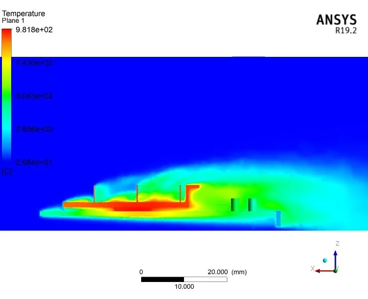
Fig No. 12. Temperature contour on plane.
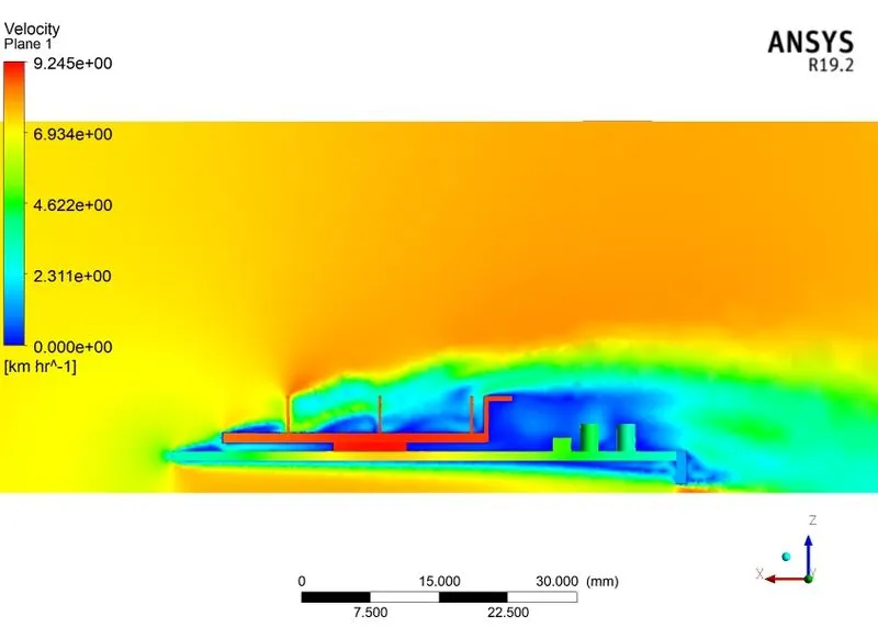
Fig No. 13. Velocity Contour on plane.
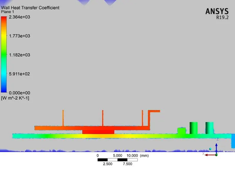
Fig No. 14. Wall heat transfer coefficient.
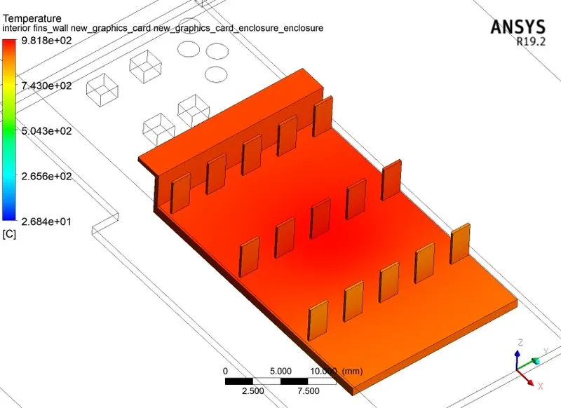
Fig No. 15. Maximum temperature of fin.
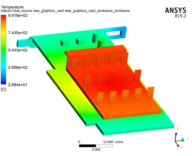
Fig No. 16. Maximum temperature of processor and fin.
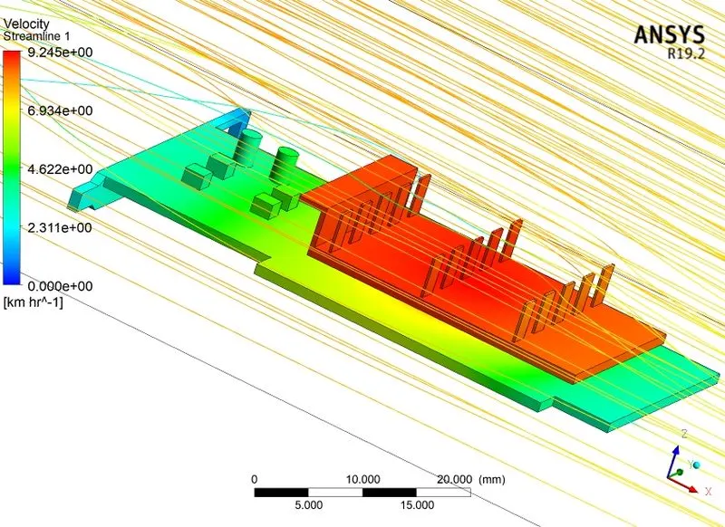
Fig No. 17. Velocity streamlines.
- CASE II - REFINED MESH -
The velocity of inlet air at 2 m/s.
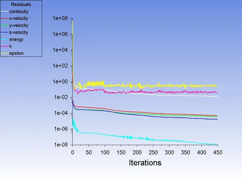
Fig No. 18. Residual plot.
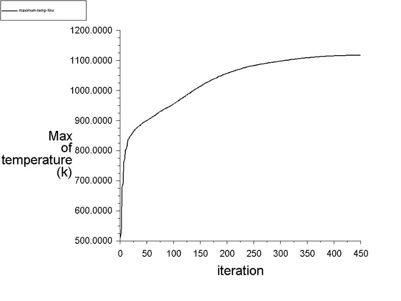
Fig No. 19. Maximum temperature of fins.
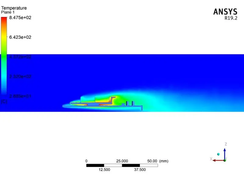
Fig No. 20. Temperature contour on plane.
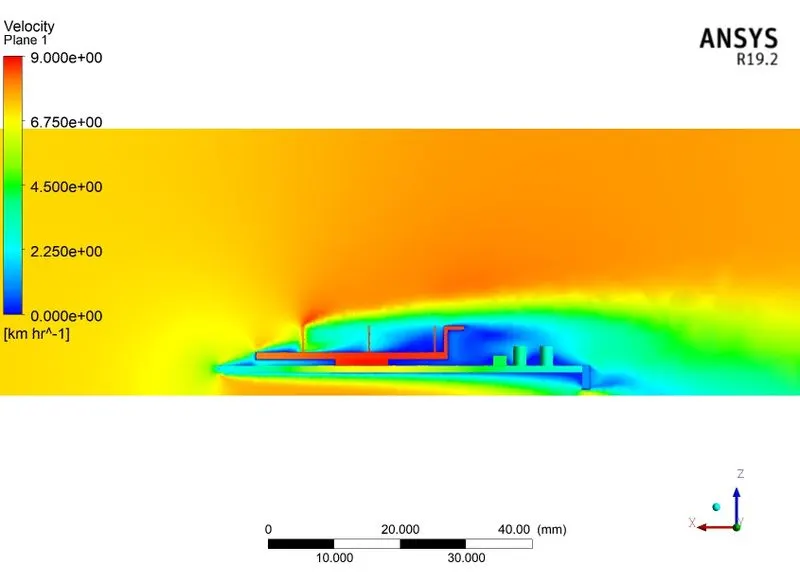
Fig No. 21. Velocity Contour on plane.
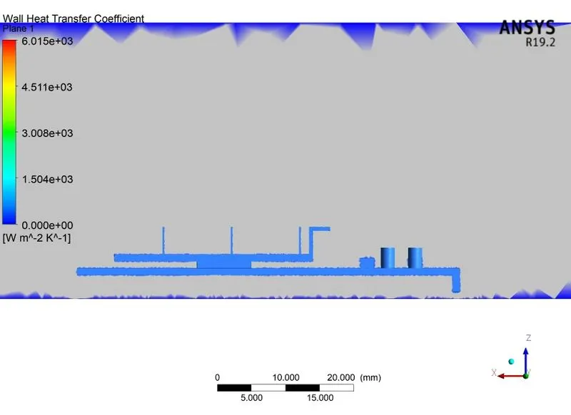
Fig No. 22. Wall heat transfer coefficient.
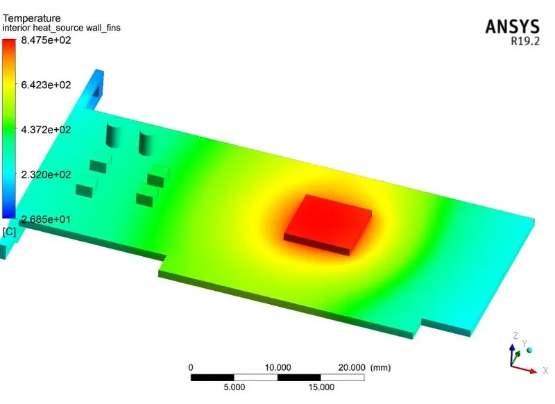
Fig No. 23. Maximum temperature of the processor.
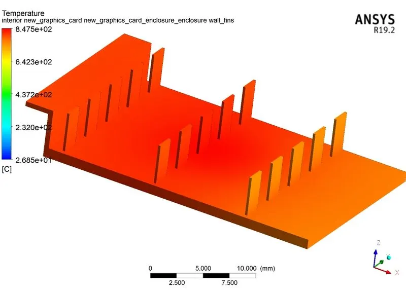
Fig No. 24. Maximum temperature of fin.
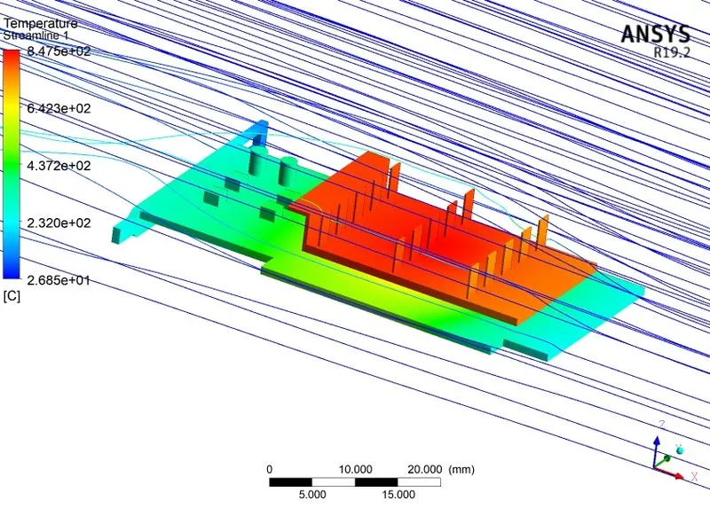
Fig No. 25. Streamlines.
- CASE III - VELOCITY 3 m/s for REFINED MESH
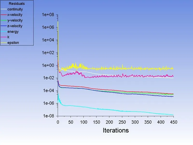
Fig No. 26. Residual plot.
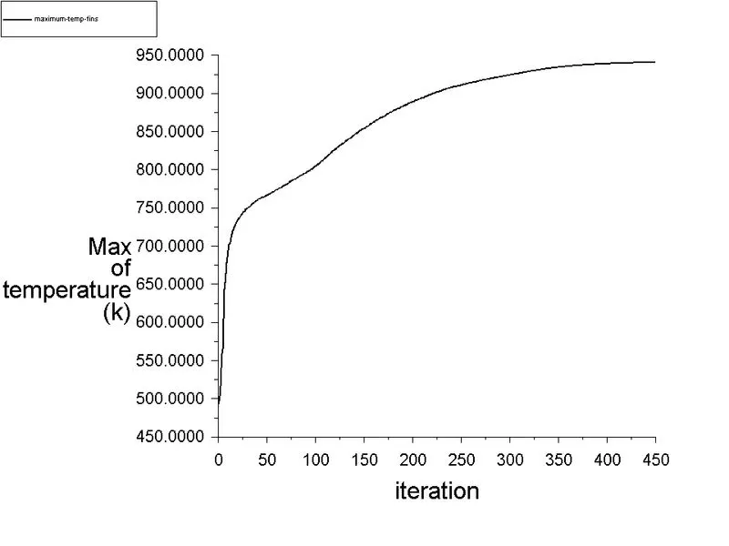
Fig No. 27. Maximum temperature of fins.
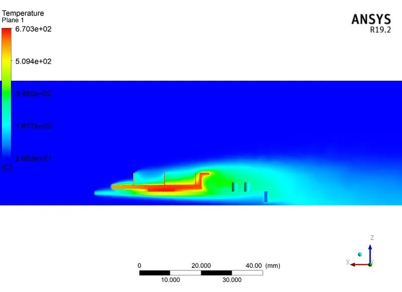
Fig No. 28. Temperature contour on plane.
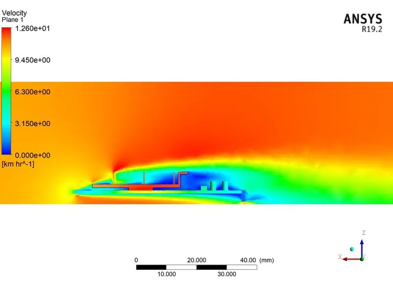
Fig No. 29. Velocity Contour on plane.
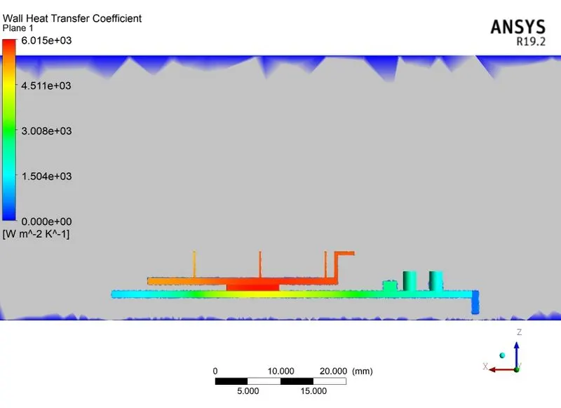
Fig No. 30. Wall heat transfer coefficient.
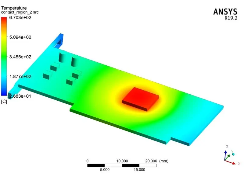
Fig No. 31. Maximum temperature of the processor.
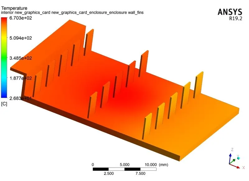
Fig No. 32. Maximum temperature of fin.
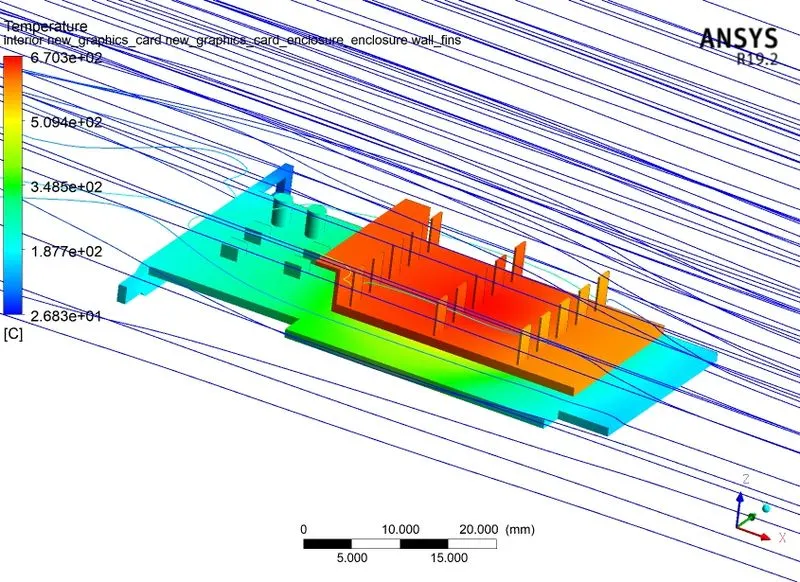
Fig No. 33. Streamlines.
- CASE IV - Velocity 5 m/s REFINED MESH
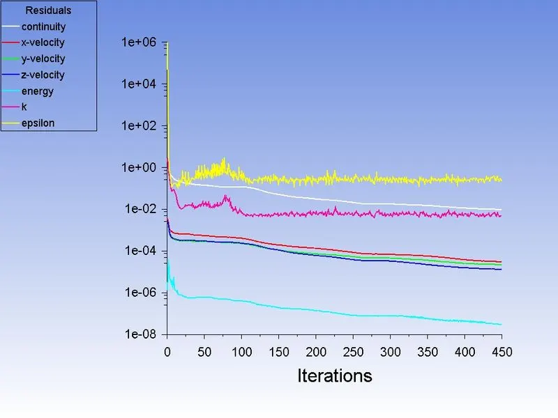
Fig No. 34. Residual plot.
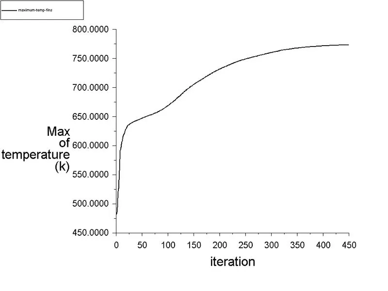
Fig No. 35. Maximum temperature of fins.
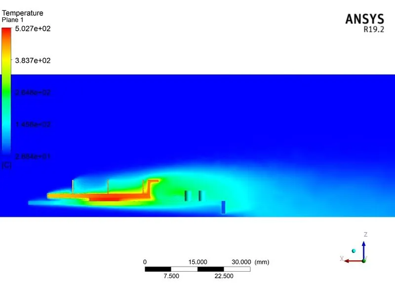
Fig No. 36. Temperature contour on plane.
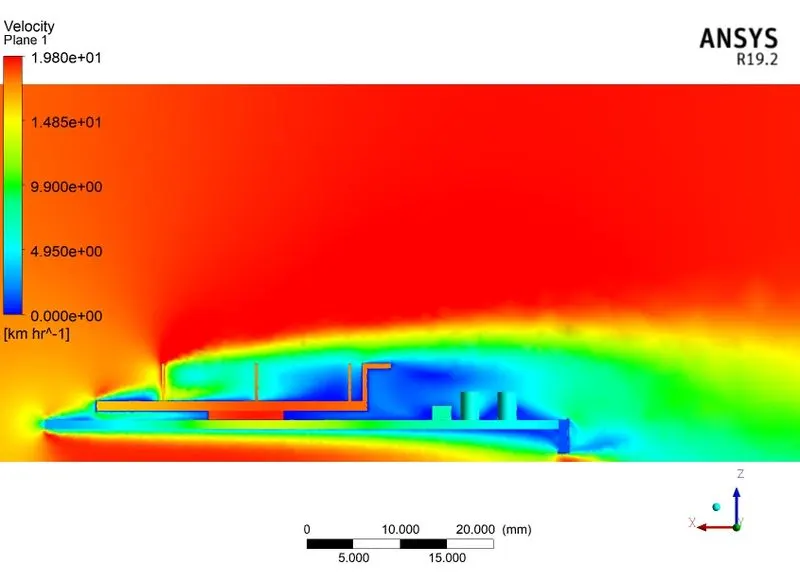
Fig No. 37. Velocity Contour on plane.
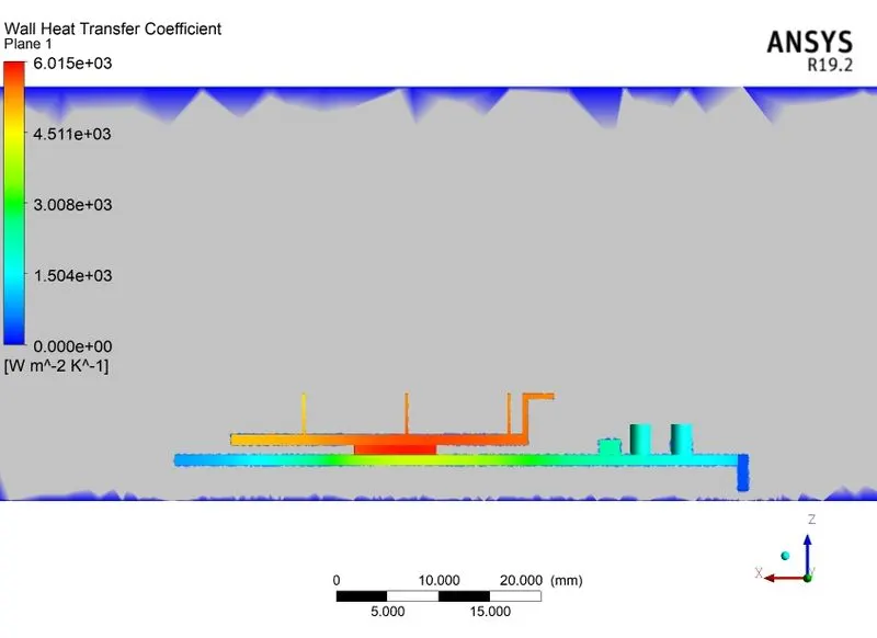
Fig No. 38. Wall heat transfer coefficient.
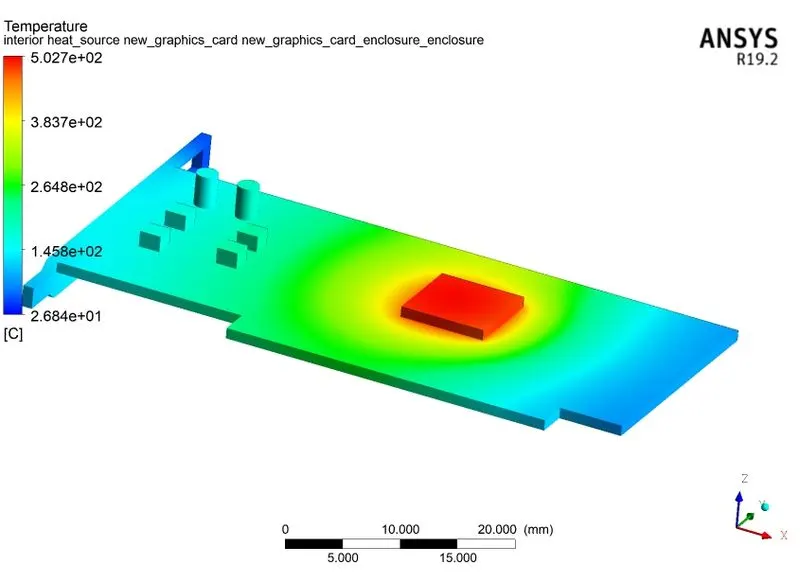
Fig No. 39. Maximum temperature of the processor.
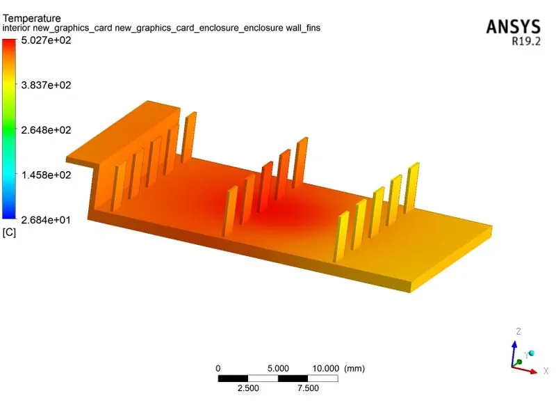
Fig No. 40. Maximum temperature of fin.
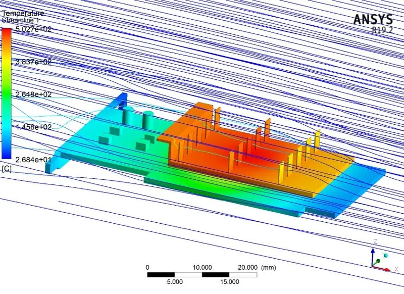
Fig No. 41. Streamlines.
- RESULTS -
Table No. 4. Max temperature and Wall heat transfer coefficient.
| Fluid Velocity (m/s) | Max temperature of fins (C) | Wall heat transfer coefficient (W/m2k) | |
| Coarse mesh | 2 | 981.8 | 2364 |
| Fine mesh | 2 | 847.5 | 6015 |
| Fine mesh | 3 | 670.3 | 6015 |
| Fine mesh | 5 | 502.7 | 6015 |
From the above table, we can say that the refined mesh gives more accurate results than the coarse mesh. The maximum temperature of the graphics card and the fins reduces with an increase in the flow velocity of the air. The temperature reduces with an increase in velocity because it increases heat transfer rate and heat is transferred from fins into the air. The heat transfer coefficient is highest in the region close to the processor since there is no airflow present so that the coefficient remains the same for all changes in velocity. The rate of heat transfer attains a steady state after the maximum possible amount of heat is transferred hence any change in velocity of air is not affects wall heat transfer. But the areas exposed to fluid have a high wall heat transfer coefficient as the velocity of the air is increased.
The convergence of the results depends upon the consistency and continuous transfer of heat to the air through convection. The main source of convective heat transfer is that of fins. When fins attain the maximum possible temperature then the results shown by the Ansys are called converged results. After 450 iterations the change in the maximum temperature of fins finds out to be maximum. Also, fins almost attain the temperature of the processor that means the heat is carried progressively and consistently through fins into the air.
- CONCLUSION -
- The refined results produce a more accurate result as compared to coarse mesh. The time to converge the results increases exponentially.
- The temperature of the processor and the fins reduces as the velocity of the air increases. This indicates that as the airflow increased the amount heat transfer rate also increases, hence increase the cooling rate of the graphics card.
- The highest heat transfer rate observed near the processor wall, which is 6015 W/m^2k. This region is not in contact with air since there is no space in between them to air to flow. In the region which experiences fluid flow the wall heat transfer coefficient increases with an increase in fluid flow.
- The potential hotspot for this problem is the heat source processor. Apart from that, the airflow is very much low and no fins provided in the lower portion of the base, which creates the potential hotspot and needs to be resolved. The amount of heat generated depends upon the workload and the efficiency of the fins to dissipates the heat.