Week 4 - CHT Analysis on Exhaust port
CONJUGATE HEAT TRANSFER ANALYSIS ON EXHAUST PORT
************************************************************************************************************************************************
- AIM - The conjugate heat transfer analysis of Exhoust port to identify the heat transfer coefficient on internal solid and verify the HTC predictions from simulations & state the accuracy of prediction.
- INTRODUCTION -
Conjugate means coupled, connected, related. Heat is defined as energy transferred by a virtue of temperature difference. It is customary to refer to different types of heat transfer mechanisms as modes. In general, heat transfer describes the flow of heat (Thermal Energy) due to temperature differences and the subsequent temperature distribution and changes. The study of the transport phenomenon concerns the exchange of momentum energy and mass in the form of conduction, convection, and radiation. The term conjugate heat transfer analysis type allows for the simulation of heat transfer between solid and fluid domains by exchanging thermal energy at the interface between them. In solids conduction often dominates whereas in fluid convection usually dominates. Conjugate heat transfer is observed in any situation. For example, heat sinks are optimized by combining heat transfer by the condition in the heat sink with the convection in the surrounding fluid.
Conjugate heat transfer analysis used in various application like convective heat transfer through heat exchangers, various electronic equipment, in recent times data centers, small electronic equipment, condensers of various refrigerating equipment, automobile engines, etc. conjugate heat transfer analysis is the main integrated part of surface heat transfer between fluid and solid or solid-solid. Conjugate heat transfer analysis of exhaust port is carried out to identify the wall heat transfer coefficient and to observe different contour profiles to improve the design and analysis of the exhaust port.
- GEOMETRY -
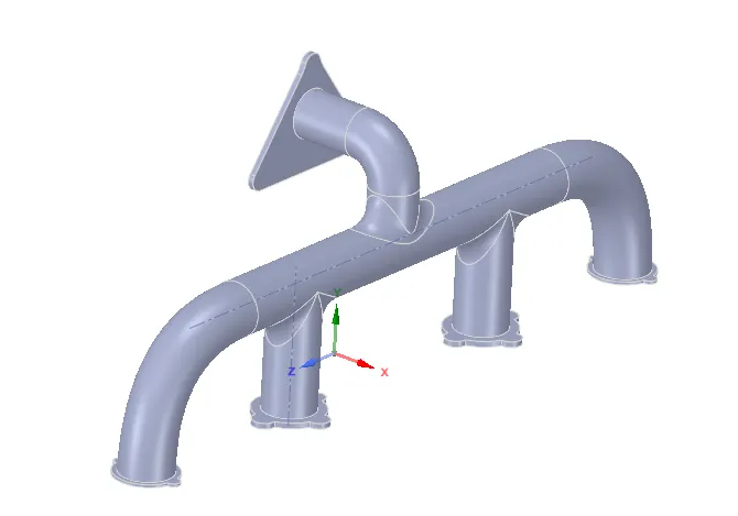
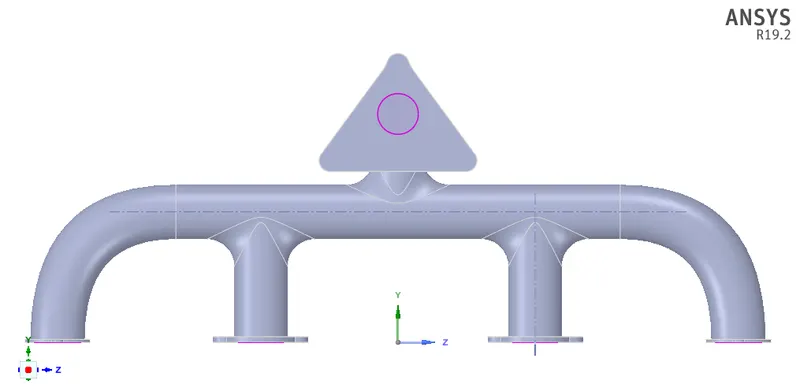
Fig No. 1. Geometry details and share topology.
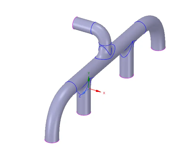
Fig No. 2. Inner Fluid Volume.
- MESHING -
I. BASELINE MESH-
Primarily focused on developing mesh using baseline mesh provided by ANSYS and try to figure out result later then improve the mesh by various means. In the first place, we have enabled the share topology and mesh accordingly to achieve the best possible accurate results. Baseline mesh is provided to get the start and to generate baseline simulation to get an overview.
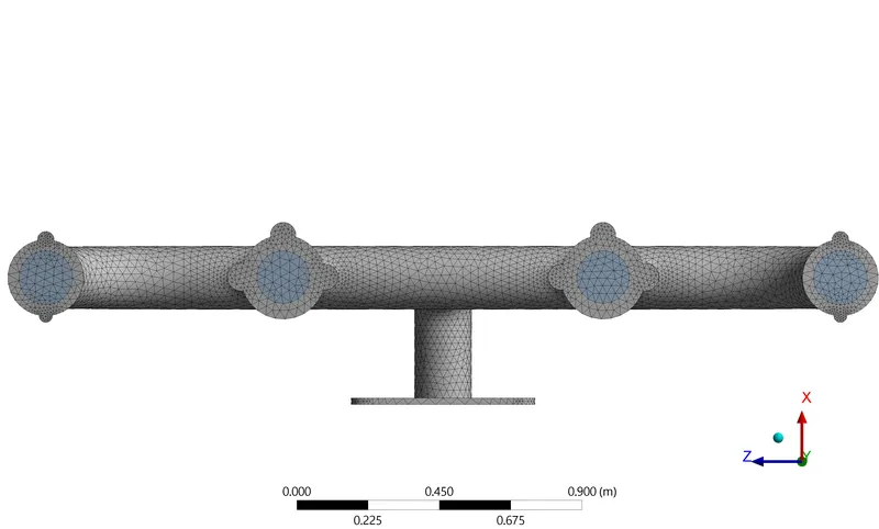
Fig No. 3. Baseline mesh.
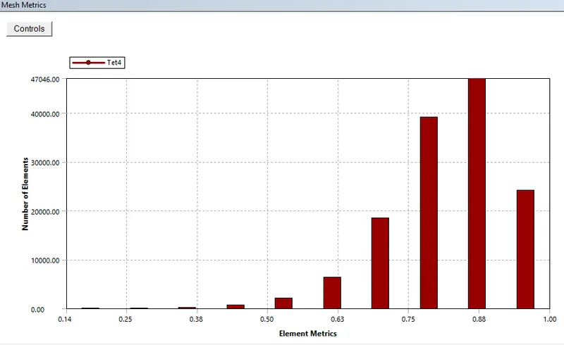
Fig No. 4. Baseline mesh metrics.
II. REFINED MESH -
In refined mesh, the results need to make more accurate and from the result, the near-wall treatment for the wall/surface heat transfer coefficient needs to be developed to achieve such a thing we primarily need to modify the mesh basically we are going to reduce the mesh size of overall body and add inflation layer at the inner body.
To calculate the total inflation layer thickness,
1. Reynold number -
`Re = (rho*v*D)/mu = (1.225*5*0.15)/(1.7894*10^-5) = 51344.02`
For internal flow Re>4000, considered as the turbulent flow.
In viscous sublayer Y+ value is in the range of 1 and 5, we considered it to be 1.
2. Skin friction coefficient -
`C_f = 0.00576*(Re)^(-1/5) = 6.581*10^(-3)`
3. Wall shear stress -
`tau_w = 1/2*C_f*rho*U_oo^2 = 0.1007`
4. `U_t` -
`U_t = sqrt(tau_w/rho) = 0.2868`
5. Rearrange for Y from the equation of Y+
`y = ((Y+ * nu)/U_t) = 0.0509mm`
The first layer thickness is 0.0509mm.
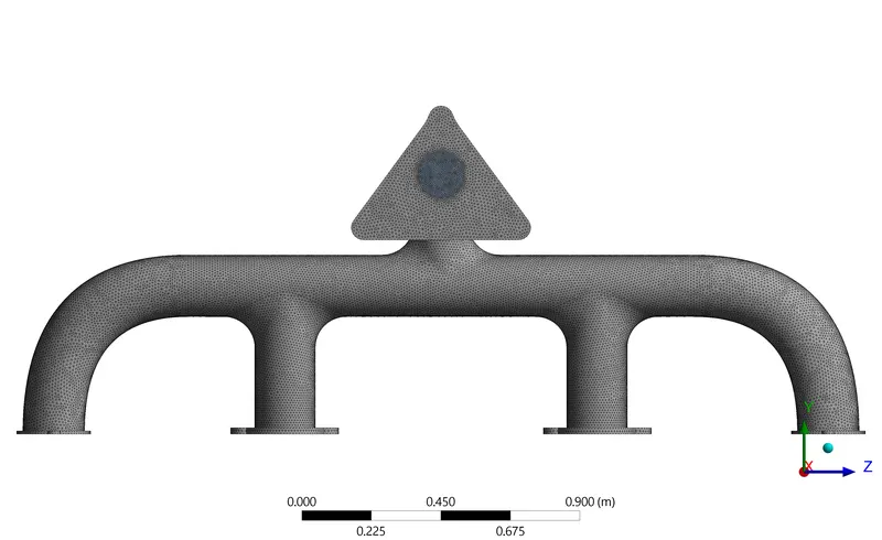
Fig No. 5. Refined Mesh.
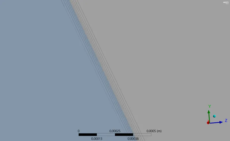
Fig No. 6. Inflation layer of first layer thickness as 5.09 e-5 m.
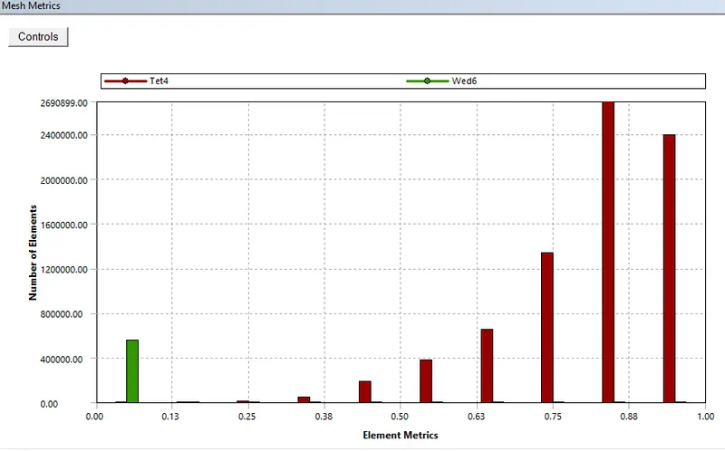
Fig No. 7. Refined mesh metrics.
Table No. 1 Nodes and elements statistics.
| Baseline mesh | Refined mesh | |
| Nodes | 27484 | 440227 |
| Element | 137926 | 1402861 |
- SETUP -
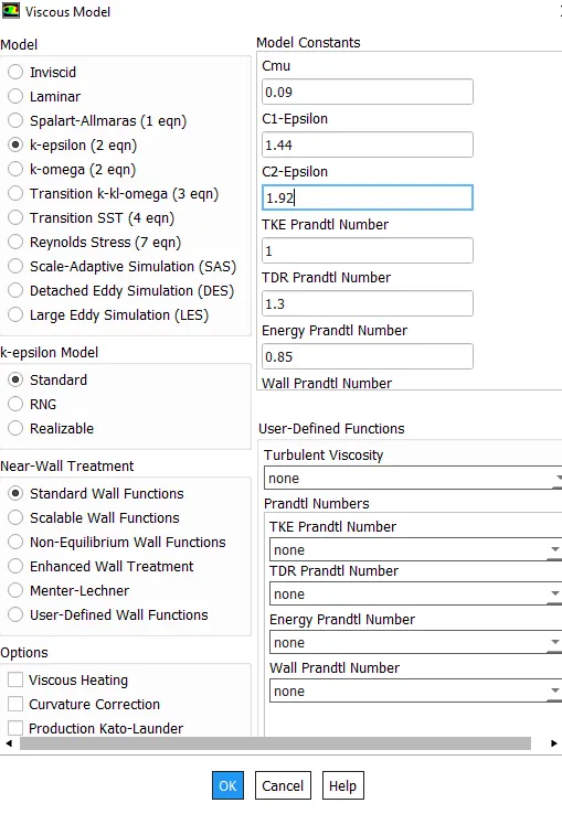
Fig No. 8. Viscous Model.
The Fluid and solid properties and the material selected default for this particular problem.
- Aluminum -
- Density - 2719 kg/m^3.
- Specific Heat - 887 j/KgC
- Critical specific volume - 0.00141 m^3/Kg
- Critical temperature - 6299 k
- Air -
- Density - 1.225 kg/m^3.
- Specific Heat - 1006.43 j/KgC
- Thermal Conductivity - 0.0242 W/mK
- Viscosity - 1.7894 e-5 Kg/m^3
- Critical specific volume - 0.002857 m^3/Kg
- Critical temperature - 132.3 k
BOUNDARY CONDITIONS -
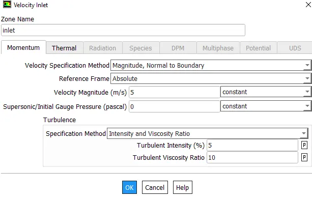
Fig No. 9. Inlet Boundary condition with 700K temperature at the inlet.
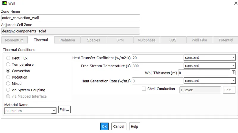
Fig No. 10. Convection outer wall heat transfer coefficient.
- RESULT -
I. BASELINE MESH
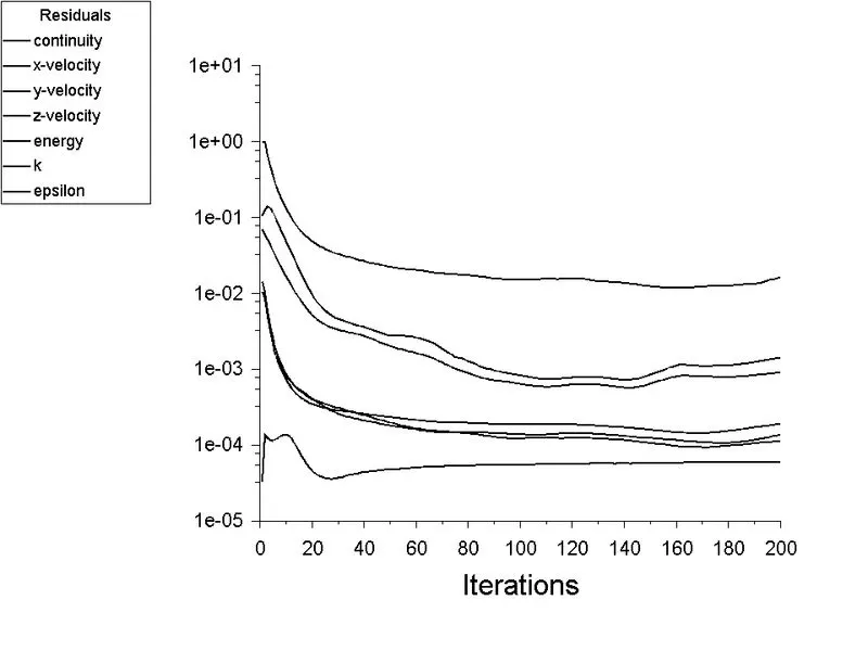
Fig No. 11. Residual plot.
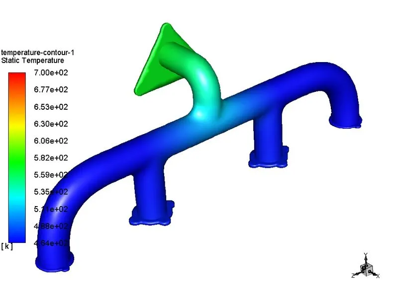
Fig No. 12. Temperature Contour.
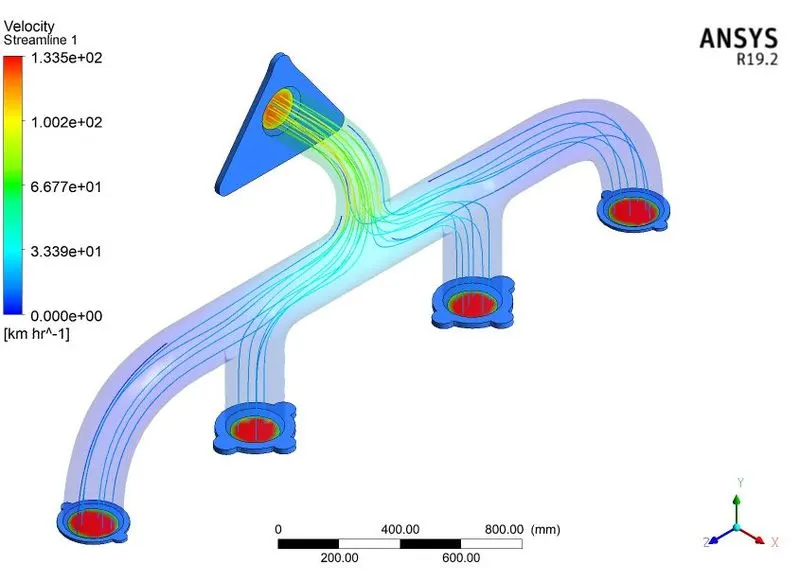
Fig No. 13. Velocity Streamline Contour.
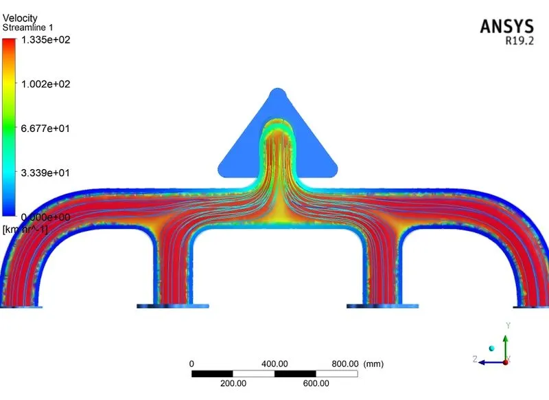
Fig No. 14. Temperature plane plot.
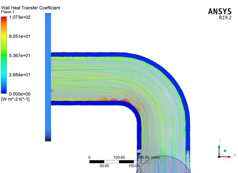
Fig No. 15. Wall heat transfer coefficient.
II. REFINED MESH
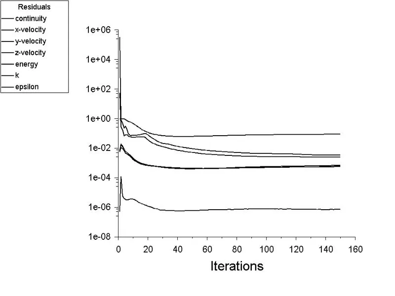
Fig No. 16. Residual plot.
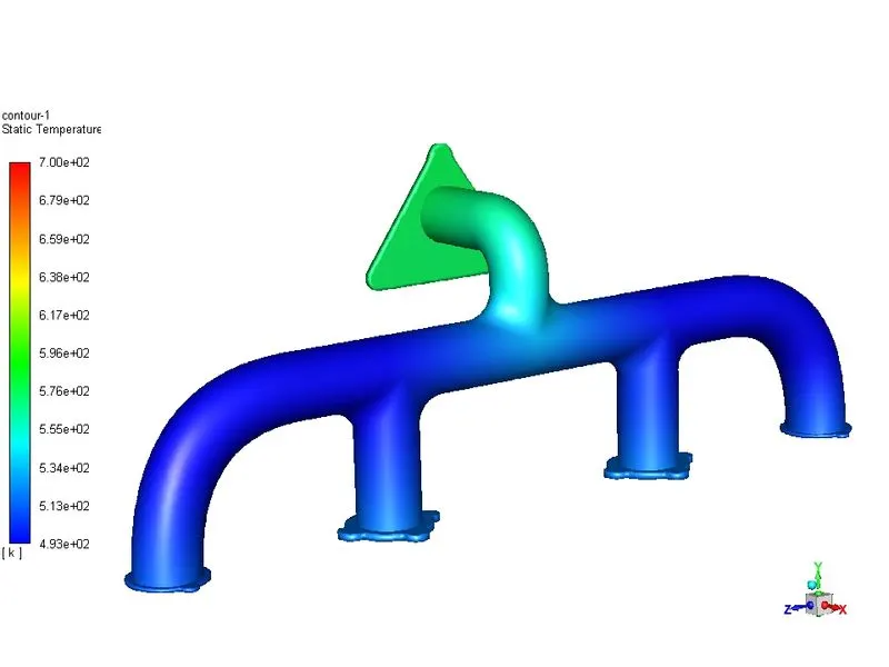
Fig No. 17. Temperature Contour.
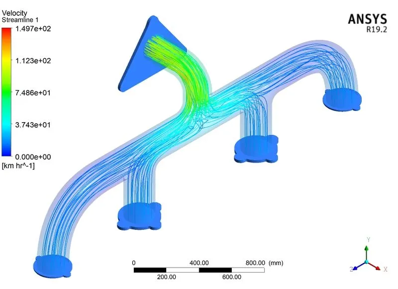
Fig No. 18. Velocity Streamline profile.
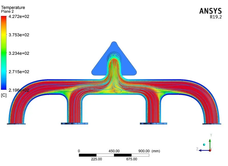
Fig No. 19. Temperature plane plot.
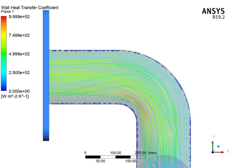
Fig No. 20. Wall heat transfer coefficient.
- The accuracy of the result can be validated by comparing it with experimental data or
- By mesh independency test to validate the accuracy of the result.
- By theoretically calculating the heat transfer coefficient using nusselt number.
- Nusselt Number -
Nusselt number is defined as the ratio of convective to conductive heat transfer across a boundary. The convection and conduction heat flows are parallel to each other and to the surface normal of the boundary surface and are all perpendicular to mean fluid flow in simple cases.
Heat flow through convection -
`q_(conv) = h*DeltaT`
Heat flowe through conduction -
`q_(cond) = (k*DeltaT)/L`
Now,
`Nu = (h*DeltaT)/(k*(DeltaT)/L)`
Where,
L - Characteristics length
k - Thermal conductivity of fluid
h - Convective heat coefficient
The significance of the nusselt number is higher is the number more will be the rate of heat transfer by convection than by conduction. It helps to find h convective heat transfer coefficient due to free or forced convection.
- Prandtl Number -
The Prandtl number is a dimensionless number approximating the ratio of momentum diffusivity to thermal diffusivity. The Prandtl number is often used in heat transfer and free & forced convection calculation. It depends on fluid property it does not include the characteristic length scale of the geometry.
Pr = Momentum Diffusivity/Thermal Diffusivity = `(mu*C_p)/k`
where,
`mu` - Viscosity`
Cp - Specific heat at constant pressure condition,
k - Thermal Conductivity
Value of Prandtl number signifies the thickness of thermal boundary layer as compared to the thickness of hydroboundary layer. Prandtl number tells us how fast the thermal diffusion takes place in comparison with momentum diffusion.
- Dittus-Boelter Equation -
For fully developed (hydrodynamically and thermally) turbulent flow in a smooth circular tube, the local nusselt number may be obtained from the well-known Dittus-Boelter equation. The Dittus-Boelter equation is easy to solve but is less accurate when there is a large temperature difference across the flid and for rough tubes.
`Nu = 0.023* Re_(Dh)^0.8*Pr^0.4`
where,
Dh - Hydraulic diameter
Re - Reynold number
Pr - Prandtl number
Nu - Nusselt number
By comparing the nusselt number we can calculate for heat transfer coefficient and validate it.
- CONCLUSION -
- Results are more accurate with finer mesh.
- Wall heat transfer coefficient captured better with a fine mesh having inflation layers.
- Heat transfer increases in fluid velocity which means heat transfer takes place mainly because momentum diffusivity or convection heat transfer dominates the heat transfer.
- No significant change in temperature contours with fine mesh.
- With proper Y+ value, it captures near-wall characteristics properly.
- Wall heat transfer coefficient changes drastically from 107.3 to 999.94 `W//m^2k` due to mesh refinement. This ensures the selection of the proper Y+ value plays very important role in deciding the accuracy as well as the precision of the analysis.