CHT Analysis on a Graphics card
Intro/Theory
Ever wondered why a game works smoother in your friend’s PC and structs on yours? I know how it feels, been there myself. It is because of the systems specs. Some of the important once being storage device type (SSD/HDD), number of cores, RAM, GPU etc. For gamers, the most important spec is the GPU i.e., Graphics processing unit, it is also called as a Graphics card.
But, how is a graphic card able to provide such smooth visuals? The key is its built and design, the number of transistors it holds, the cooling system it relies on. Most GPU’s have almost a billion to trillion transistors running simultaneously. The work of these transistors is to simply do mathematical operations and read the inputs and outputs in desired manner. A million operations every fraction of second, amazing isn’t it?
I do 10 Math problems in an hour and get tired. It takes me another hour to realize that I have made a mistake. So, do these transistors not get tired? They do, but in a completely different form. They get heated up, real fast. In fact, around 99%-100% of the power consumed by a graphic card is converted to heat.
The amount of heat generated depends on the input power and the volume of the processor/unit. A typical Graphic card is rated at 125W-175W of power, i.e., an average of 150W and is around 8*8*1 mm in size, which is pretty small. This means that the heat generated is massive. It is so high that it can literally burn the components around it.
Hmmm…, So why are our laptops not on fire yet?
The reason is the amount of time and money spent on reseach and development of these GPU's. This is also the reason why they are super-expensive. These GPU's are fitted with liquid and fan cooling systems. Cheaper GPU's utilize the surface area for cooling.
To know more about this hot component, read this really amazing blog by techspot
https://www.techspot.com/article/1988-anatomy-graphics-card/
Aim
The objective of this project is to simulate a flow around a fan-cooled GPU. Instead of actually modelling a fan and running a simulation, we would just define the flow velocity in the set-up. This will save a lot of computational power.
Different flow velocities will be used to find the variation of maximum temperature generated. This is an important parameter because it will help us understand what will be the temperature near other components on the mother-board or the PCB on which the processor is placed. These components are temperature sensitve and can go all crazy if the temperatures rise above a acertain limit.
Another property that we will study is the heat transfer coeffecient, this will help us understand how good is the heat transfer taking place between fins and the flow around it, the processor and flow around it.
Pre-processing
Software - Ansys Fluent
Model
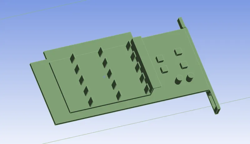
Above is a picture of a typical Graphic card. The top most structure with an array of building like structures called fins is used to increase the surface area. The bottom most/ next visible structure is the base/PCB-Printed Circuit Board. The cubical and cylindircal structures on the PCB are the electrical components that we are trying to protect from excess heat. There is another component, not visible in the above picture, between the fin structure and base, adn it is called as the processor. It is the most important one. In this model, its size is 8mm*8mm*1mm.
Before Meshing this structure, do remember to create a enclosure around it, share topology and clear interferences between different components.
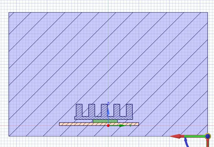
Mesh
Refined Mesh
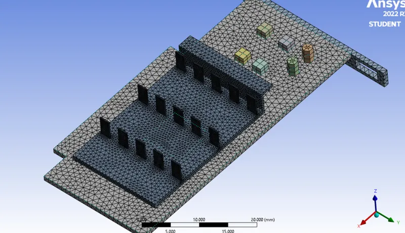
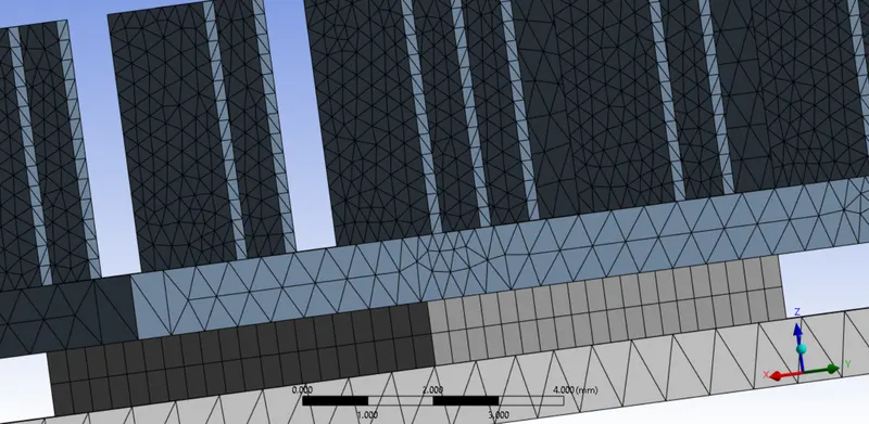
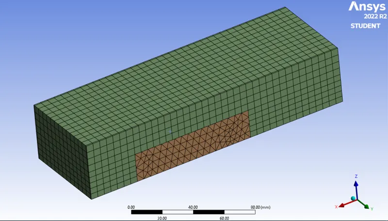
It is important to have the cells in all the three directions in the processor. Also, since most of the convection takes place around fins and processor, it is important to have these areas refined.
Set-up
- Pressure based
- Steady
- Energy equation included
- viscous model - k-omega SSTpressure velocity coupler - SIMPLE/COUPLED
- Material
Enclosure - Air
Processor - Gold
Fins - Copper
Base(PCB) - Aluminum - Power input = 10W
Average power input is usually 150W, but since we do not have additional cooling systems in this simulation, the temperatures would be too high and unrealistic for the electronic components to be functional, so it is assumed that the power input is 10W. - Heat generated = Power/volume = 156250000 W/m^3
Inlet velocity = 3m/s
Inlet air temperature = 300 k (room temperature)
Convergence 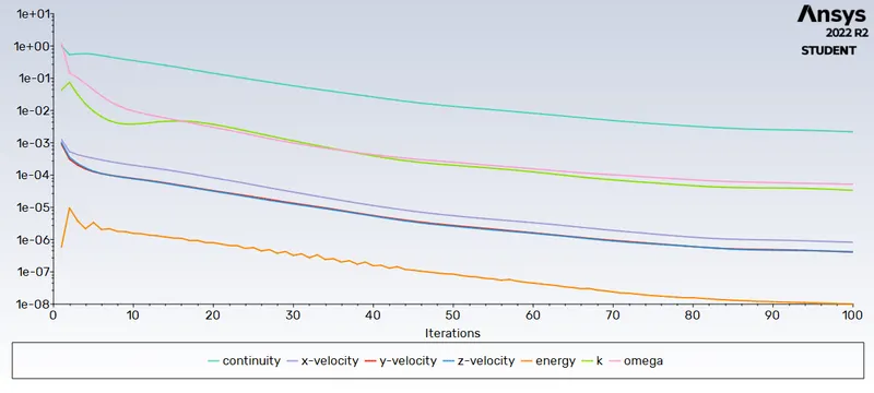
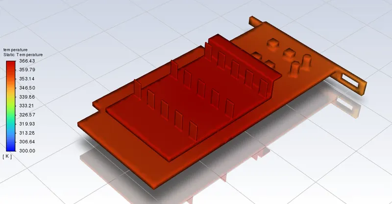
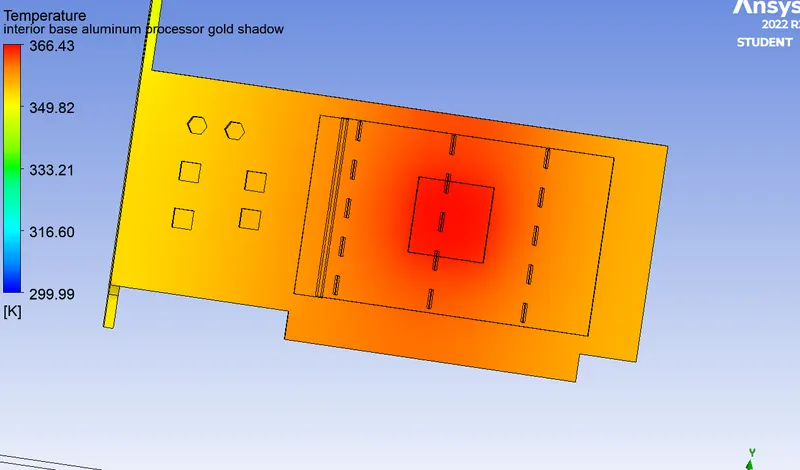
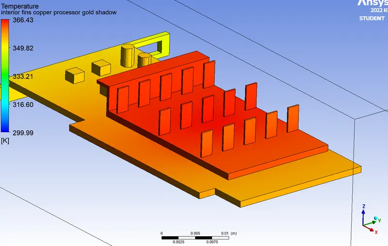
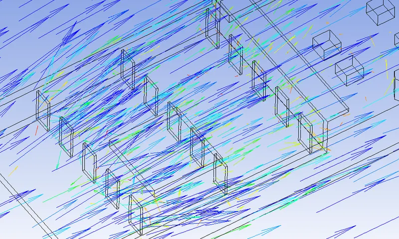
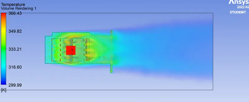
The above volume rendered picture shows that the flow behind the graphic card is at a considerably higher temperature than the inlet flow. This is because it has observed heat from the graphic card.
Also, the fins are hotter than the PCB, this is because of their material properties. Aluminum is a bad conductor of heat, when compared to copper.
Comparision bwn 1m/s, 3m/s and 5m/s
Convergence
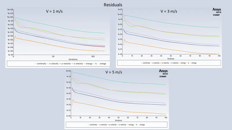
In all the cases, convergence was obtained. One way to know this is the following residual plots, which almost become vertical at 100 iterations
Other parameters like maximum temperature, Heat transfer coefficient at fins and walls also become constant. This clearly mean that the solution has converged.
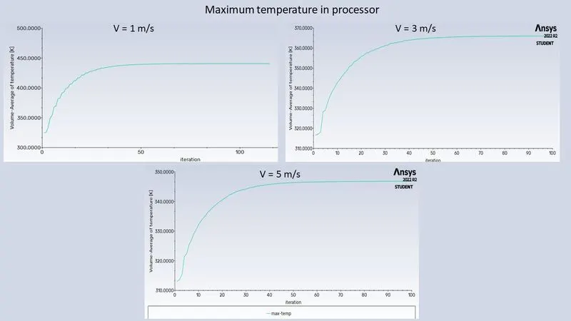
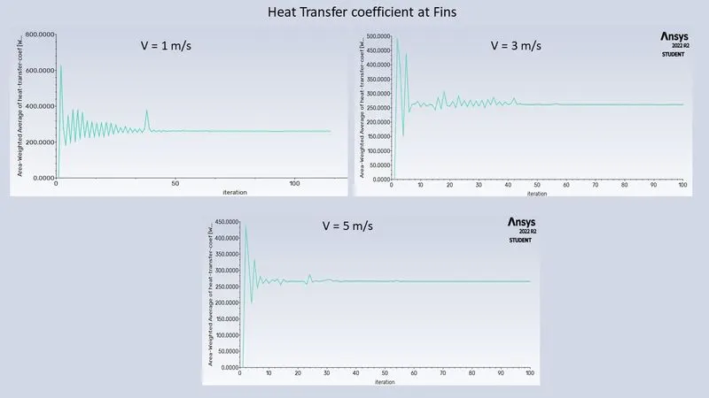
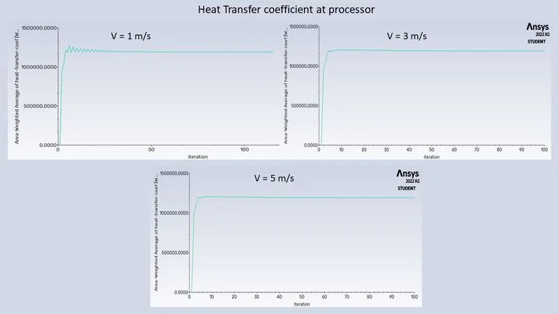
| Case/Parameter | Maximum temperature (k) | HTC (Fins) | HTC (Processor) |
| v=1m/s | 440* | 265* | 1000000* |
| v=3m/s | 365* | 265* | 1000000* |
| v=5m/s | 345* | 265* | 1000000* |
*The values have been rounded.
Conclusion/Inference
- There is a fall in maximum temperature when the velocity of flow is increased.
- The amount/percentage of fall in temperature decreases as the velocity increases. At this stage, a new coling method or a change in design has to be incorporated to further decrease the maximum temperature.
- Potential hotspot was obviously the processor and the material around it. This range of hot region depends on the material.
- The flow density decreases as the the flow moves past the first row of fins. This is not good, as the amount of air interacting with the next row of fins would be less. One way to understand why the flow density falls is the upcoming obstruction in the flow path. An other way to see this is, as the flow moves past the first row of fins, it gets heated up and moves above due to its density.
- Heat transfer coeffecients at fins and processor more or less are same in all cases. This might mean that the amount of heat that can be transferred to air is limited. It is just that as air moves faster, new cooler air absorbs the heat released by the processor/fins.
How to increase accuracy of this problem and make it more realisitc ?
- Refine Mesh - Add additional enclosure, add inflation layers.
- Material properties must be made as close as they are in real graphic cards. This can be difficult to do, as the material properties and information are protected by the intellectual property rights of the company.
- Probably, change the direction of flow.