CHT Analysis on a Graphics card
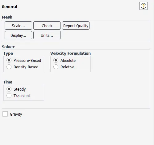
AIM: To perform steady-state conjugate heat transfer analysis on a model of graphics card in Ansys Fluent.
INTRODUCTION:
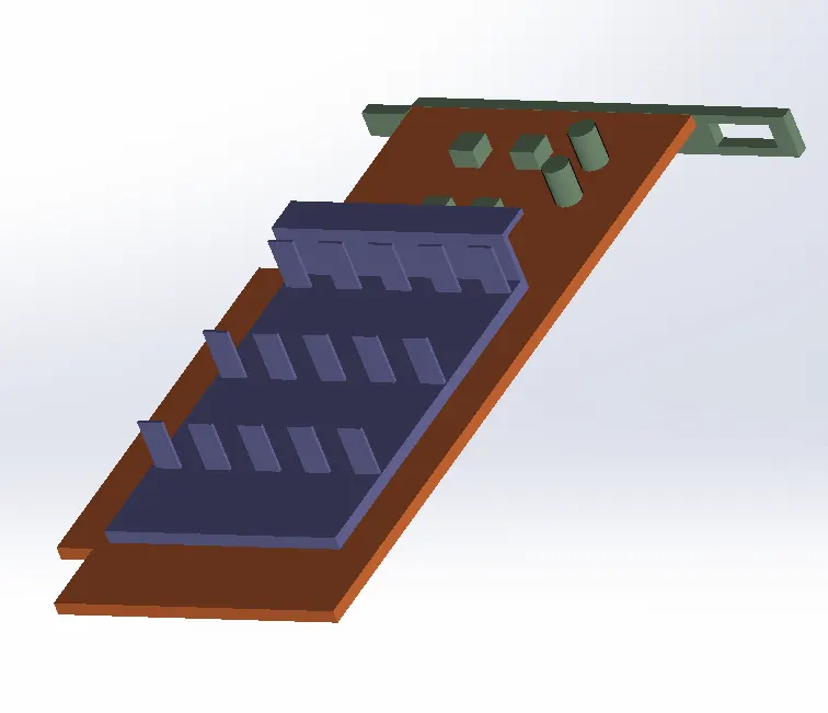
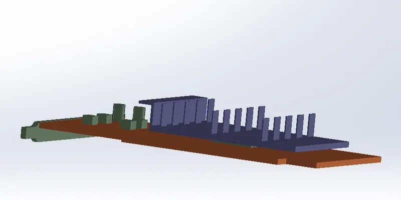
Conjugate heat transfer arises naturally in most instances where external and internal temperature fields are coupled. Thus, heat transfer analysis becomes essential for design of many engineering objects. In this project, we are interested in analysis of a graphics card model. It comprises of three main parts namely the base, processor and Fins. The main focus is on the accurate prediction of heat transfer, temperature at the surfaces and potential hotspots. The simulation is run for the best mesh combination using a pressure-based solver in Fluent.
OBJECTIVES:
The general purpose of this project is to learn how to carry out the conjugate heat transfer analysis on a given model in any case using Fluent. A part from this, there are specific tasks and objectives to be attained throughout this works which are as follows:
- Run the three simulations for three different inlet velocity ranging between 1 to 5 m/s and discuss the results.
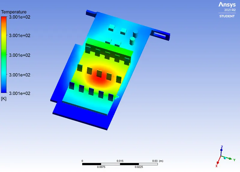
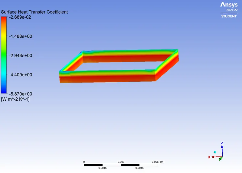
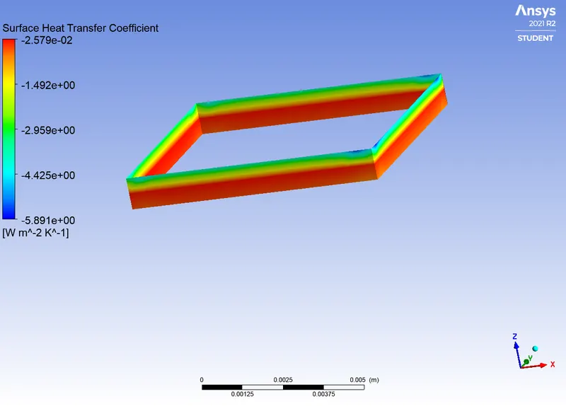
- Determine the maximum temperature and heat transfer coefficient attained by the processor
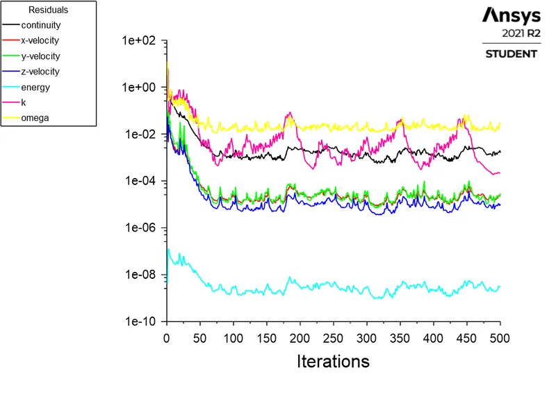
- Prove that the simulation has achieved the convergence with appropriate images and plots
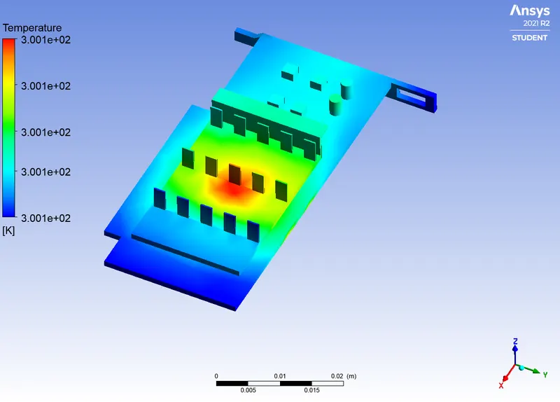
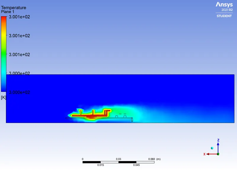
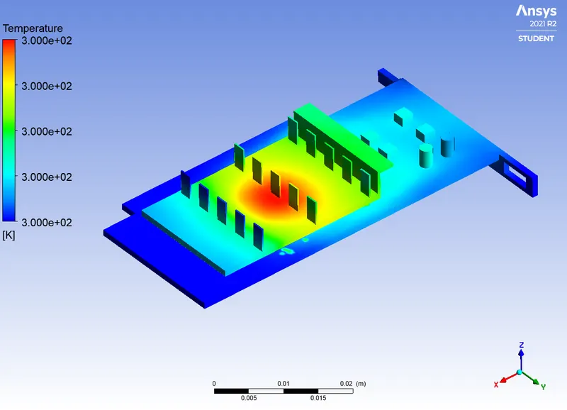
- Identify potential hot spots on the model
THEORY:
In theoretical heat convection, the only tool available was the empirical relation between heat flux and temperature difference. However, with the digital revolution, the conjugate heat transfer model was developed, replacing the empirical relationship with a heat transfer coefficient. It describes heat transfer as a result of interactions between two objects using a mathematical formulation that describes the process of heat transfer between a body and fluid in the surrounding space. Objects are distinguished into two subdomains based on the physical processes and solutions of the governing equations. The predictions of heat transfer properties play a crucial role in many real-world engineering simulations. These include simulations of heat exchangers, HVAC (Heating, Ventilation, and Air Conditioning), combustion or burners, and electronics cooling, to name a few. The transfer of heat across the interface between fluid and solid domains is often important in these applications as well as how heat moves within each domain. As such, we are interested in CHT analysis on a graphics card.
Geometry setup:
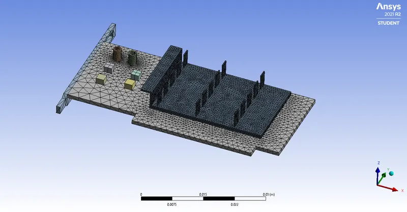
The geometry CAD file is imported in SpaceClaim for preparation.
Base
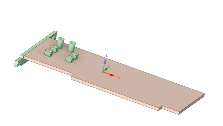
Base & Processor
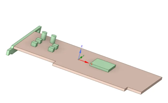
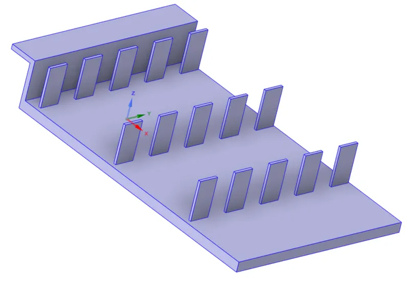
FINS
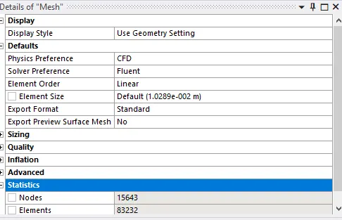
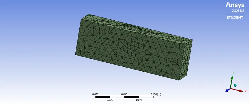
Base Mesh:
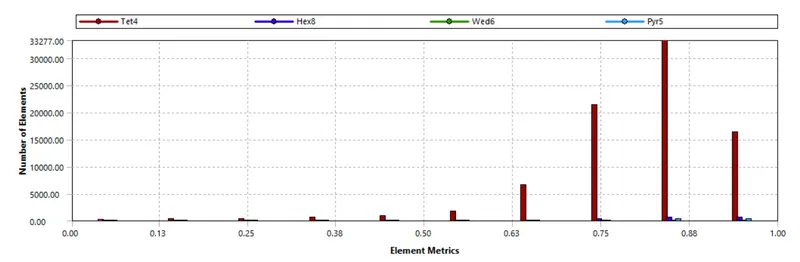
Case Setup:
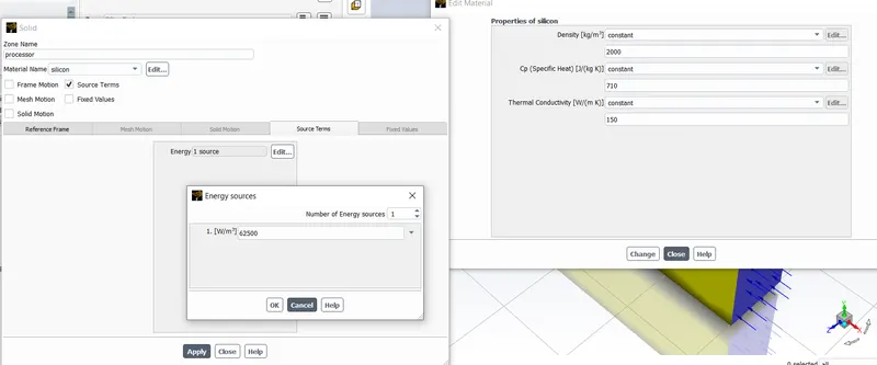
It is supposed that the heat produced by the graphics card is 4W hence the heat generation rate is calculated as follows:
`heat g en eration rate=4/(0.008×0.008×0.001)=62500000W/m^3`
This value is used to set up the source term parameters.
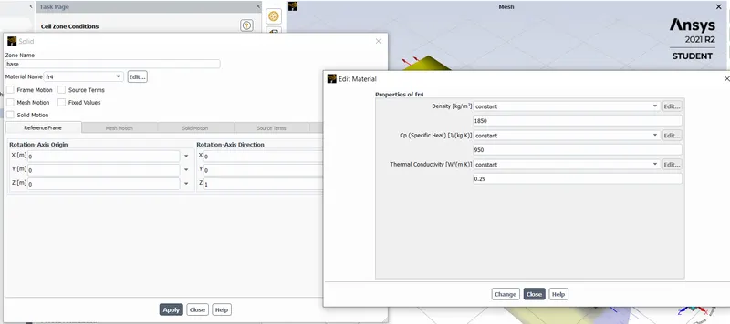
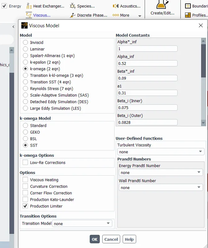
Four materials are used for different parts of the models and fluid.
Air is used as fluid flowing inside the enclosure. FR-4, Aluminium and Silicon are assigned to the Base, Fins and Processor of the graphics card respectively. FR-4 and Silicon are user-defined material in Fluent. Their details are displayed as follows:

Boundary conditions:
- Inlet
Type: Velocity inlet
Velocity:1m/s
Temperature:300K
- Outlet
Type: pressure outlet
Pressure:0 Pa(Gauge Pressure)
Temperature:300K
- Symmetry
Type: Symmetry
- Wall
Type: Wall
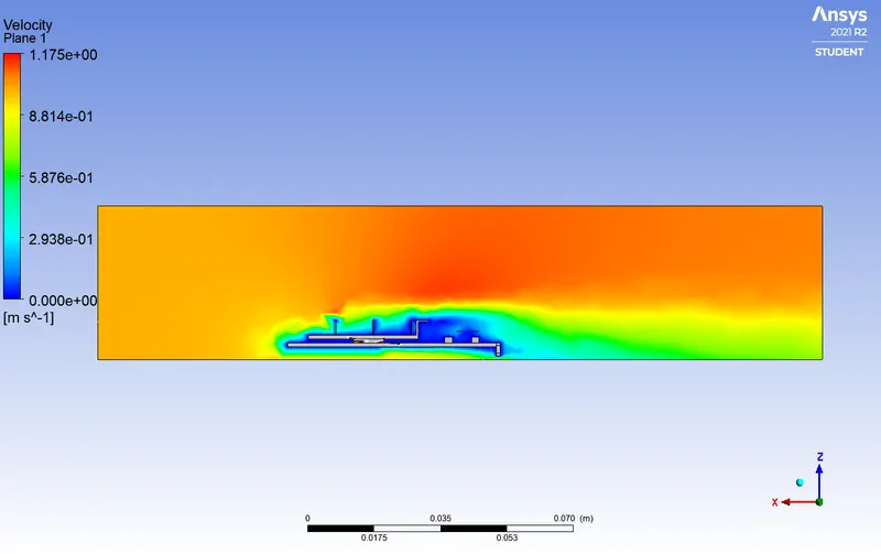
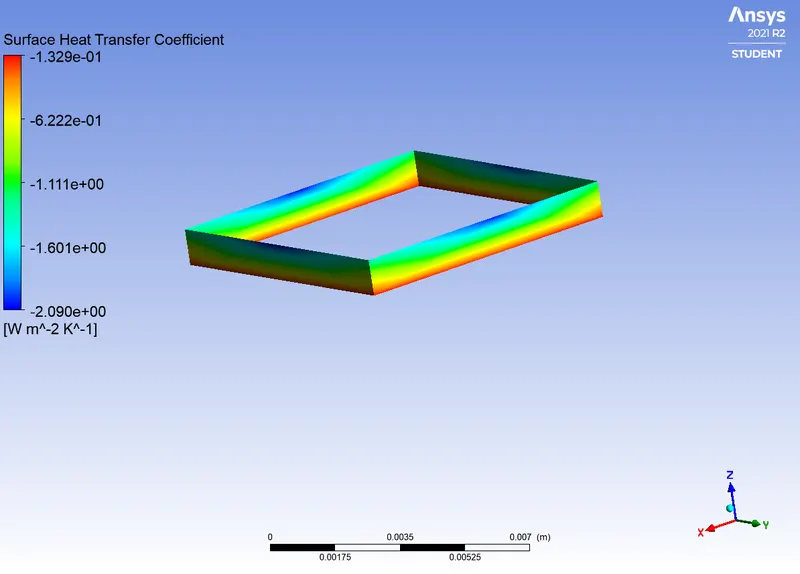
Solution of the base case
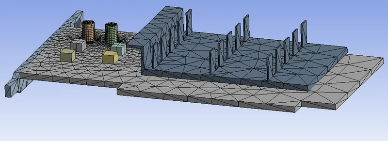
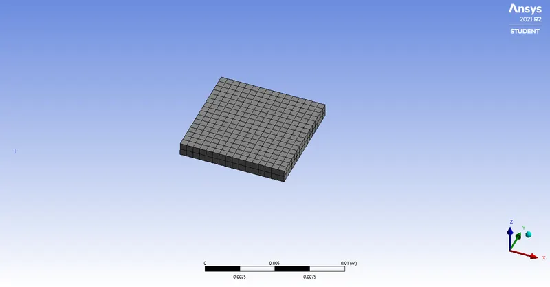
Mesh refinement:
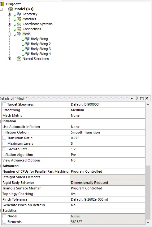
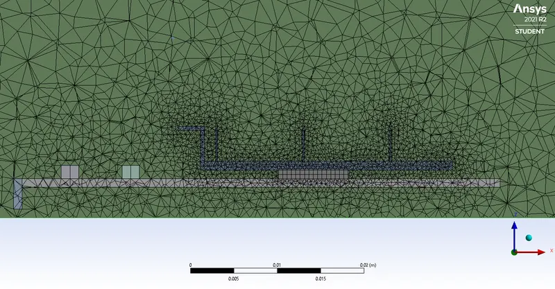
The mesh refinement is done and two other cases are run further for different velocity values. Settings ae as follows:
The element order is kept to linear and element size is set to default for the enclosure only. Then we have:
- Body sizing for Processor
Element size = 0.5mm
Curvature capture: Yes
- Body sizing for Base
Element size of the main part= 3mm
Element size of the other components of the base = 2mm
Curvature capture: Yes
- Body sizing for Fin
Element size = 0.5mm
Curvature capture: Yes
Solutions
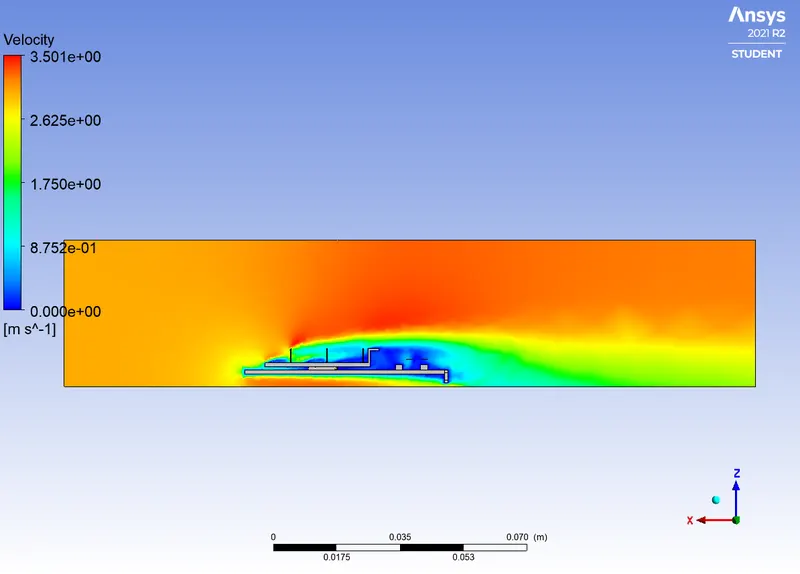
| Cases | Residuals | Velocity contour | Temperature Contour | Heat Transfer Coefficient |
| Velocity=3m/s | 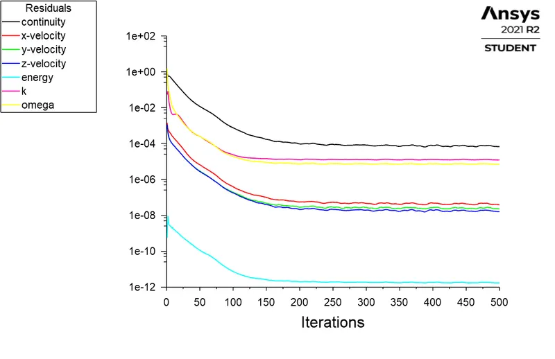 |
 |
 |
 |
| Velocity=5m/s | 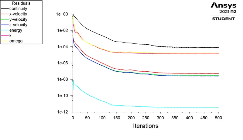 |
 |
 |
 |
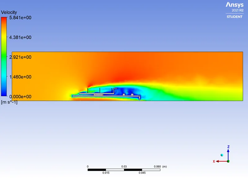
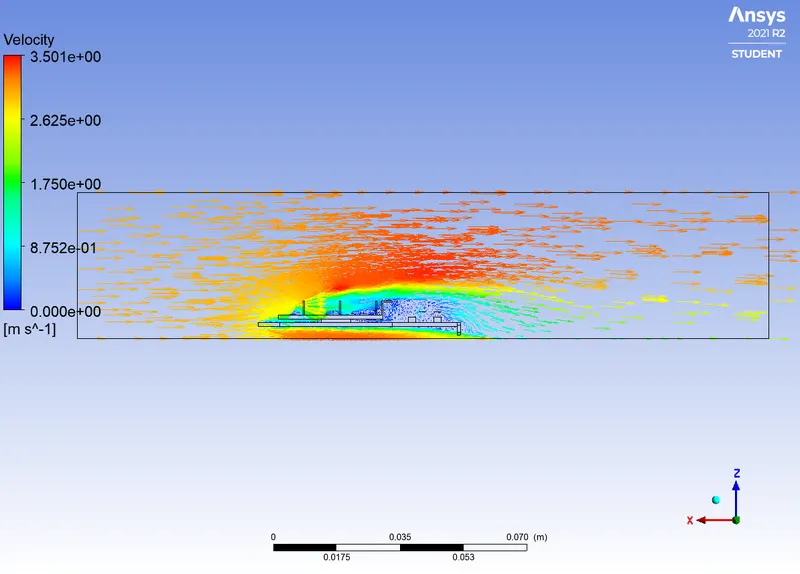
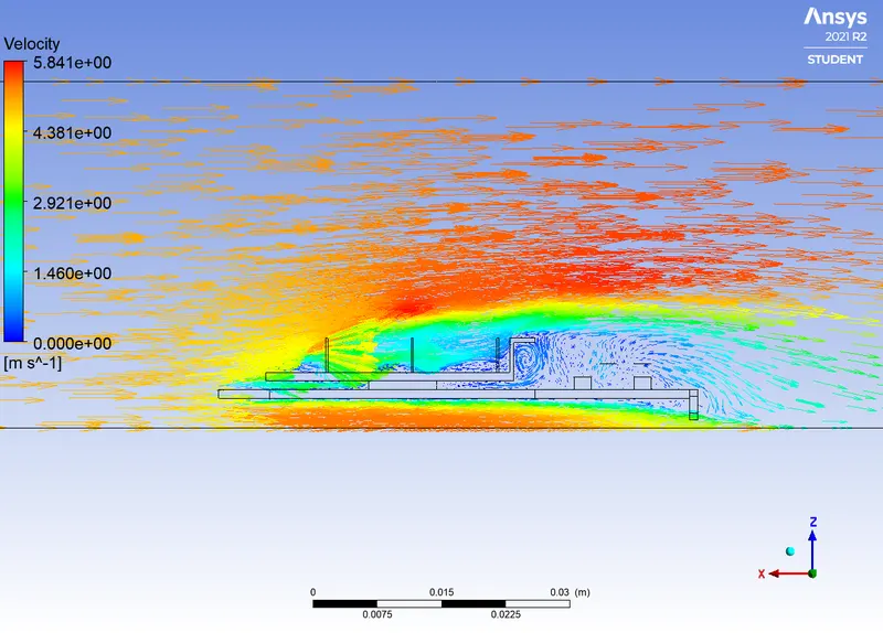
Velocity vectors at v=3m/s
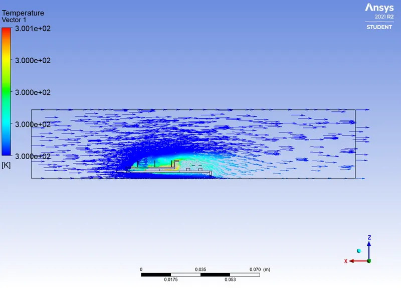
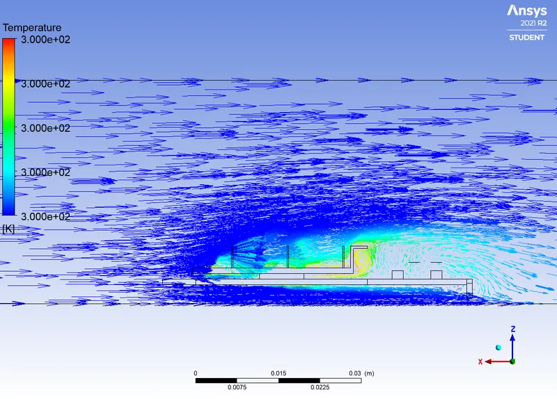
Temperature in the domain at v=3m/s
Velocity vectors at v=5m/s
Temperature in the domain at v=5m/s
|
Cases |
Maximum Temperature on the processor(K) |
Maximum HTC on the processor |
|
Case1(velocity=1m/s) |
300.11389 |
5.5356803 |
|
Case2(velocity=3m/s) |
300.05704 |
12.231467 |
|
Case3(velocity=5m/s) |
300.04106 |
19.511202 |
Conclusion:
Finally, the steady-state conjugate heat transfer analysis is performed on the given graphics card. This is done by running simulations for different velocity values using different materials for each part of the model. As the mesh refinement is done, we can notice that accurate results as far as temperature distribution are achieved. Considering the results shown by the table above, we can see that the temperature on the processor decreases as the inlet velocity increases hence the surface heat transfer increases also. This means that, the better cooling is achieved with higher velocities.