Week 6 - CHT Analysis on a Graphics card
AIM: To perform a steady state conjagate heat transfer anaysis on a model of a graphics card by choosing appropriate material of choice
for simulation.
OBJECTIVE :
- Running the simulation by varying the velocity from 1m/sec to 5m/sec for at least 3 velocities and discuss the results.
- To find out the maximum temperature and heat transfer coefficient attained by the processor.
- Proving that the simulation has achieved convergence with appropriate images and plots.
- Identifying potential hotspots on the model.
INTRODUCTION
- A graphics card( display card,video card) which generates output images to a display device(computer moniter).
- Graphics card are of two types i.e, Discrete and integrated graphics card.
- Advantages of using integrated graphics includes cost,compactness,simply and low energy consumption.
- So far as system performance is considered ,its better to use discrete graphics card.
- Discrete graphics card has its own random access memory,cooling system and power regulators.
- AMD markets CPUs with integrated graphics under the trademark Accelerated Processing Unit (APU) and Intel markets similar technologies under the ' Intel HD graphics and Iris'.
- Graphics card generates heat as they compute numerical data or some data while in use.So, dissipating the heat is very much essential in an accordance with the performance.
- cooling liquid are used in high end performance graphics card requiring 700-800 W power.Fans are provided in lower end graphics card.
- To dissipate heat more quickly we need to increase the heat transfer coefficient around the fins provided in graphics card.
- By increasing the velocity ,the heat transfer coefficient increases.Thus , heat transfer rate increases.
SOLVING AND MODELLING APPROACH
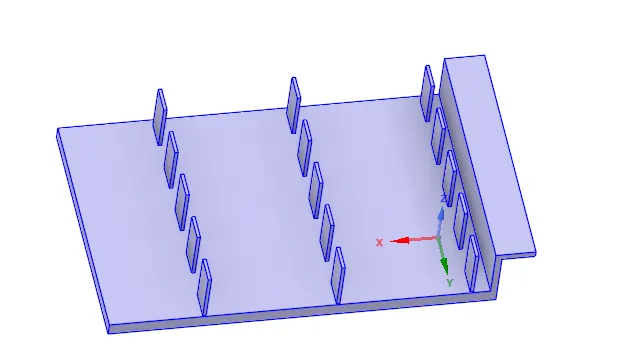
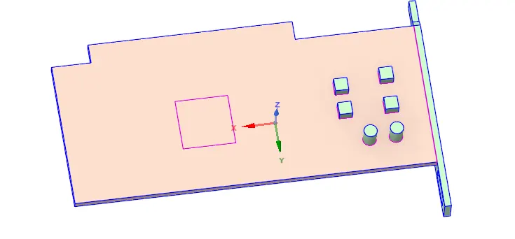
Fig. 1 Fin surface Fig. 2 Base
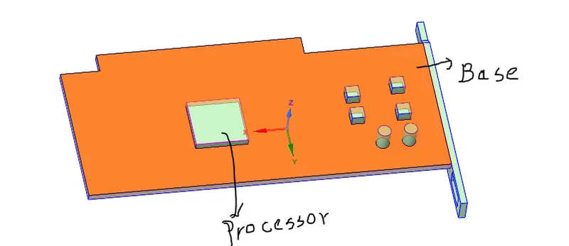
Fig. 3
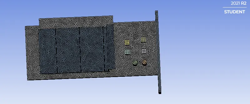
Fig.4 mesh of graphics card( 396305)
More refined mesh
|
|
PRE-PROCESSING AND SOLVER SETTING
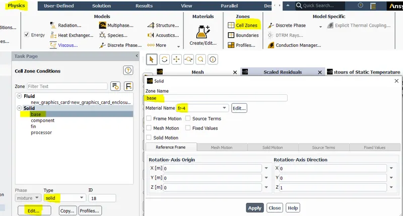
Fig.1 Selecting material for Base
- Composite material (FR-4)is choosen as it has properties which is we are concern about.
- The base should be of insulator type, so that it does not conduct electric for safety point of view.
- The material is mixture of eposy and fiberglass making it flame retardant.
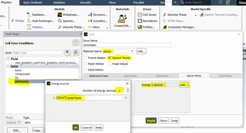
Fig.2 Selecting material for Processor
- The silicon material is selected for processor, as it is a semiconductor, having both conducting and insulating properties.
- To insert more transisters and incorporate more switches in silicon is more reliable and cost effective.
- The volumetric heat generated by processor= (power)/(volume of processor)
lets take power input = 35 watt
volume of processor= 8mm*8mm*1mm=`64mm^3`
- Heat generated=`0.546875*10^(9)`
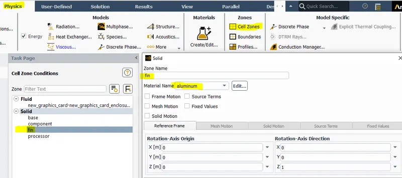
Fig.3 Selecting material for fin
- Aluminium is choosen for fin material as it has high thermal conductivity.The purose is to dissipate heat as soon as possible and make the GPU performace better .
- Keeping cost as a factor,it is availabe within the price range.
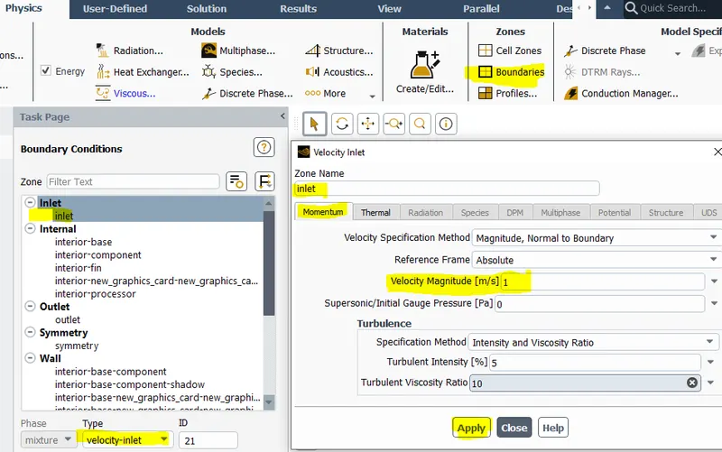
Fig.4 Setting inlet boundary condition
- First of all the inlet velocity value is taken between 1 to 5(m/s) and then take two other value of velocity from 1-5 (m/s) different from first one.
- In this set up inlet velocity value is taken as 1,3,5 m/s respectively.
RESULTS
CASE 1
- Turbulence Model = K-epsilon
- Mesh size element =10mm
- Bodysizing (fin) =0.5mm
- Body sizing (Base) =1mm
- Body sizing (processor) =1mm
- Number of mesh elements =396305
|
Inlet Velocity 1m/s |
Inlet Velocity 3m/s |
|
Fig. 1 Temperature plane showing above the fin surface |
Fig. 2 Temperature plane showing above the fin surface |
|
Fig.3 Temperature plane showing at base region |
Fig.4 Temperature plane showing at base region |
|
Fig. 5 Potential Hotspot encounter at processor |
Fig. 6 Potential Hotspot encounter at processor
|
|
Fig.7 Plane showing Temperature Vector |
Fig.8 Plane showing Temperature Vector |
|
Fig.9 Plane shhowing Temperature Contour |
Fig.10 Plane shhowing Temperature Contour |
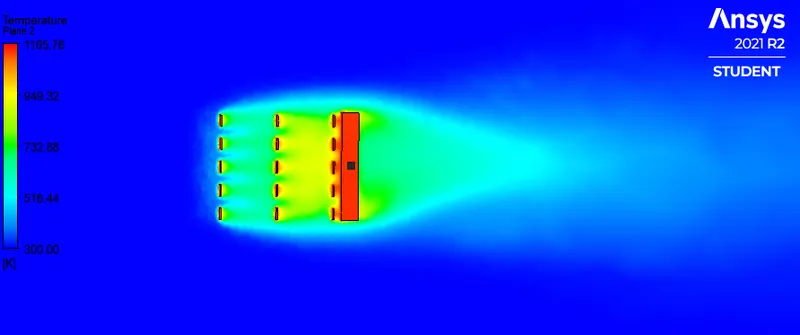
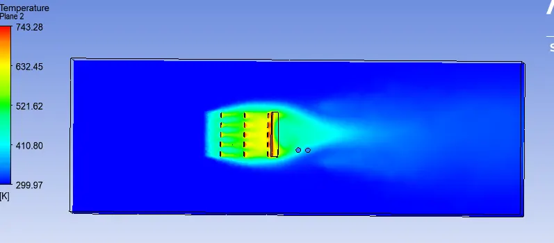
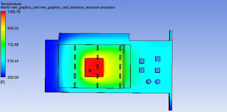
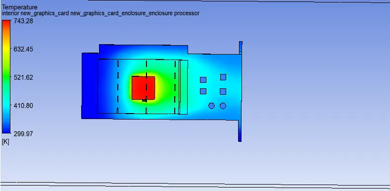
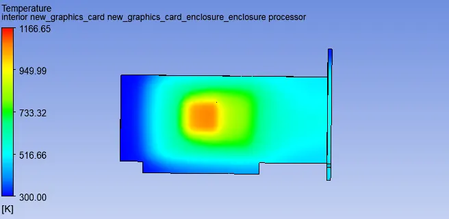
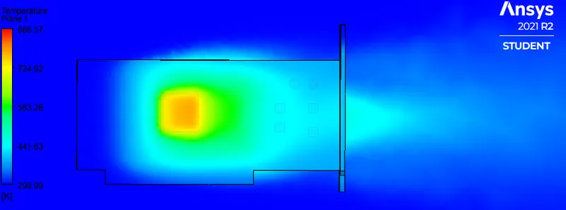
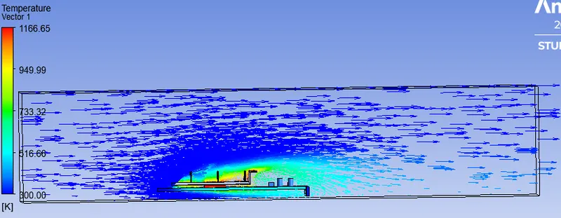
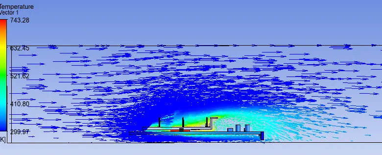
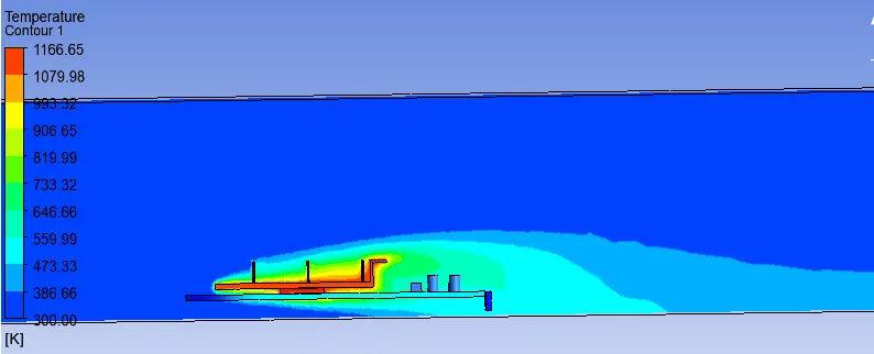
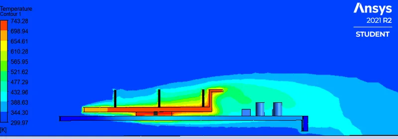
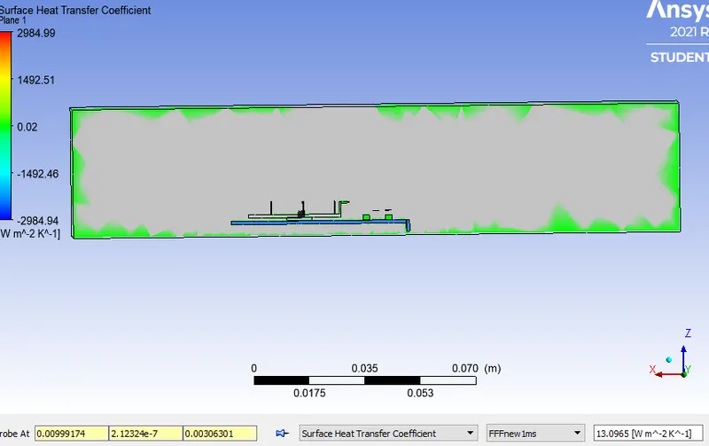
Fig.11 Surface Heat transfer Coefficient (inlet velocity 1m/s)
- The SHTC for inlet velocity 1m/s is 13.0965(w/m^2k) as the velocity is less, the SHTC is supposed to have lower value.
- The probe is taken near to the fin base surface,because the air is available at these surface.So,in order to calculate the SHTC, it might be the area to be taken into consideration.
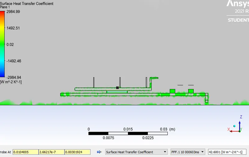
Fig.12 Surface Heat transfer Coefficient (inlet velocity 3m/s)
- As the velocity is increased from 1m/s to 3m/s, it is observed that the SHTC is increased.
- The SHTC value is 42.6001 (w/m^2k) and it has increased thrice the previous value.
- Thus increasing the velocity ,we are getting the satisfying result.
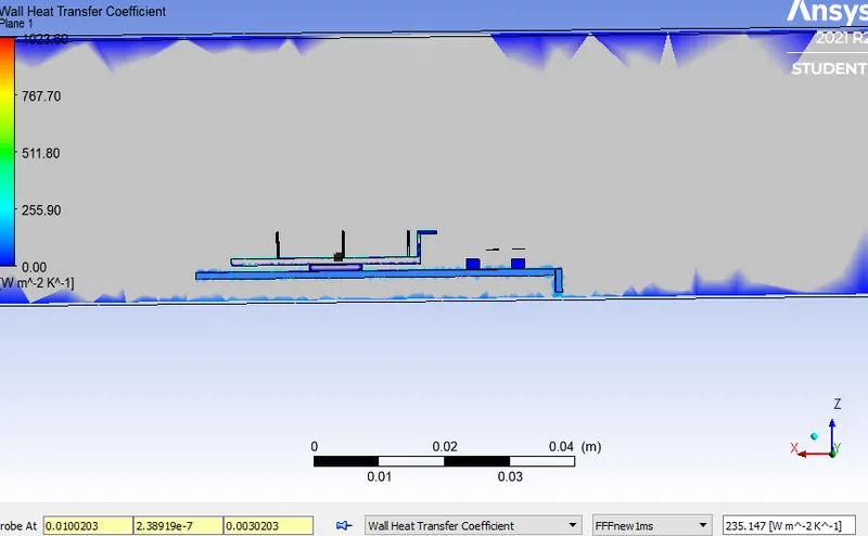
Fig.13 Wall heat transfer coefficient (inlet Velocity 1m/s)
- The WHTC value for fin base surface is 235.147`w/(m^2.k)` for inlet velocity 1m/s.
- As there is less difference between interface temperature, temperature diffference value decreases and power consumption remains same.So,heat transfer value increases but is lower than (case of inlet velocity 3m/s )h-value of 2nd case.
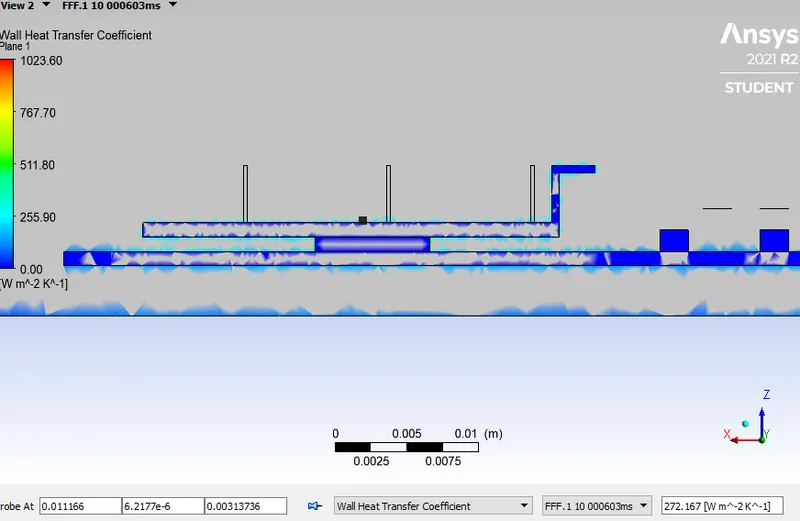
Fig.14 Wall heat transfer coefficient (inlet Velocity 3m/s)
- As we are increasing the velocity of inlet fluid, there is variation in Nusselt number.So, there is disturbance in the fluid stream as it passes over the finsurface. More intermixing takes place and the h-value increases.
CASE-2
velocity 5m/s kepsilon turbulence model
|
|
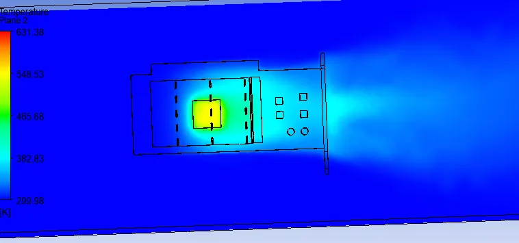
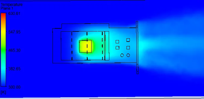
Fig.15 Temperature plane showing potential hotspot Fig.16 Temperature plane showing potential hotspot
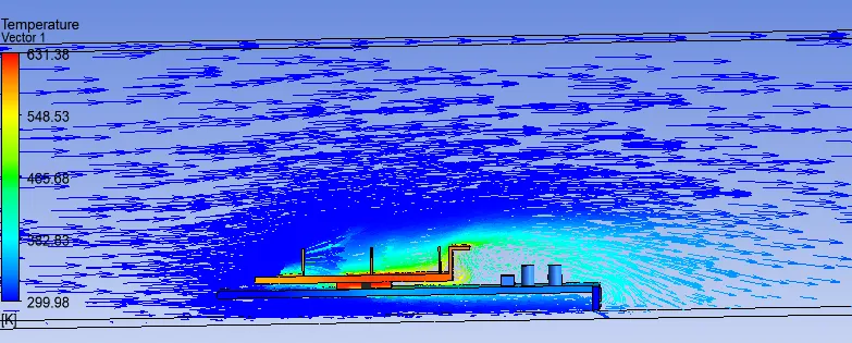
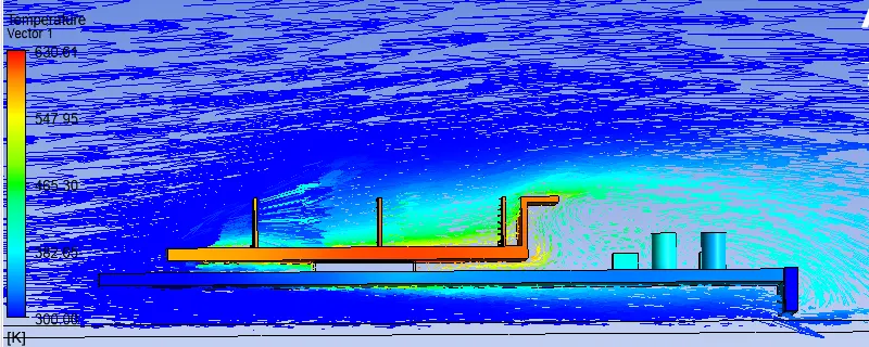
Fig.17 Plane showing Temperature vecter Fig.18 Temperature plane showing potential hotspot
over the graphics card over the graphics card
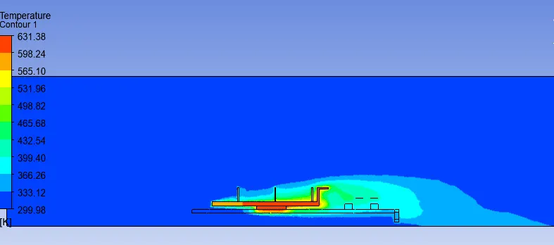
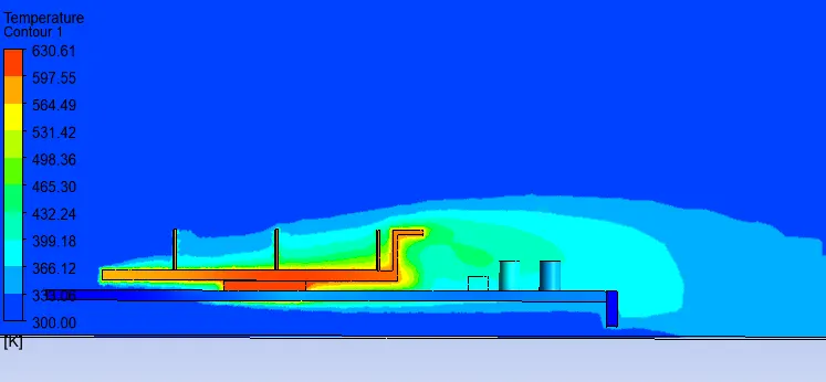
Fig.19 Plane showing Temperature Contour Fig.20 Plane showing Temperature Contour (refined mesh)
- In refined case ,we are getting more temperature contour near the fin surface having less temperature.The fluid comes in contact
with the surface and took away the heat,gets energized and carried away.
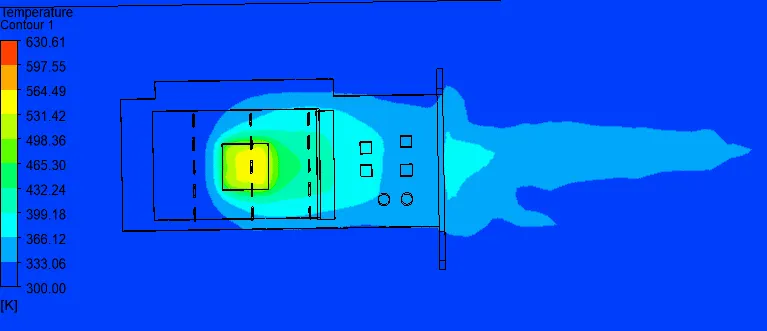
Fig.21 Plane showing Temperature Contour at fin surface Fig.22 Plane showing Temperature Contour at fin surface
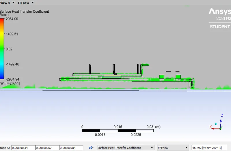
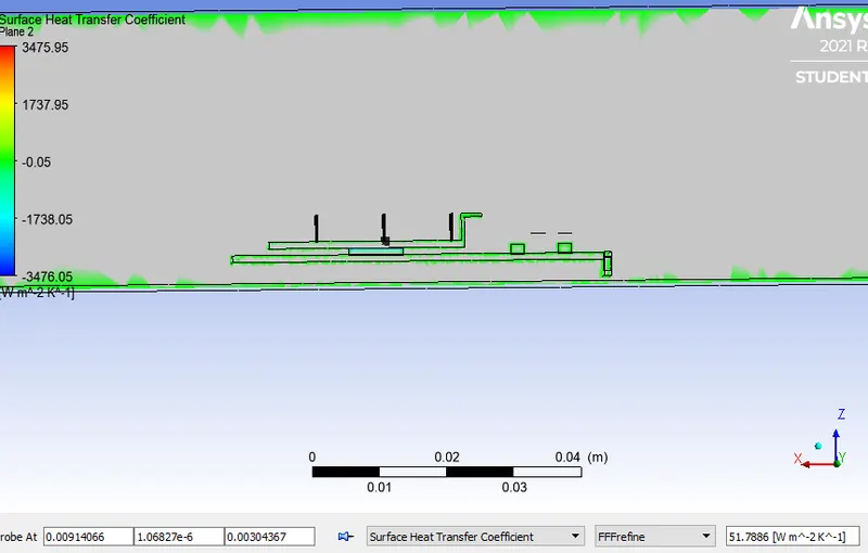
Fig.23 Surface heat transfer coefficient(45.492) Fig.24 Surface heat transfer coefficient(51.788)
- As the mesh refinement take place, there is increased in surface heat transfer coefficient.
- The value increases for same inlet velocity of 5m/s.
- As the number of elements increased, the error is get minimised and better converged result is obtained.
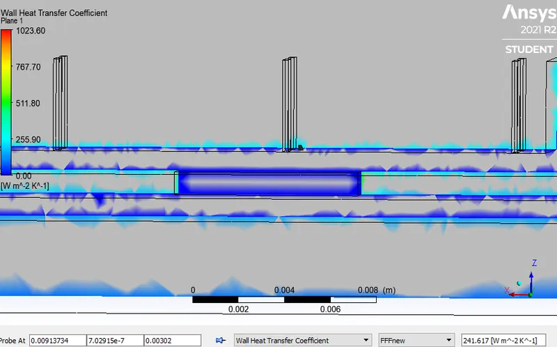
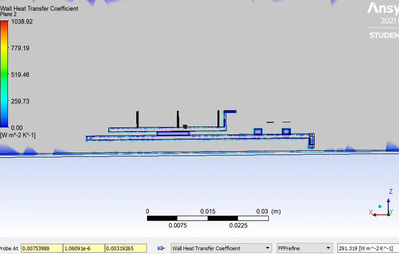
Fig.25 Wall heat transfer coefficient (241.617) Fig.26 Wall heat transfer coefficient (291.319)
|
Fig.21 Residual Vs iteration plot ( inlet velocity 5m/s) |
Fig.22 Residual Vs iteration plot ( inlet velocity 3m/s) |
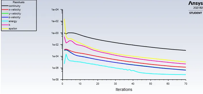
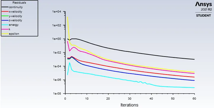
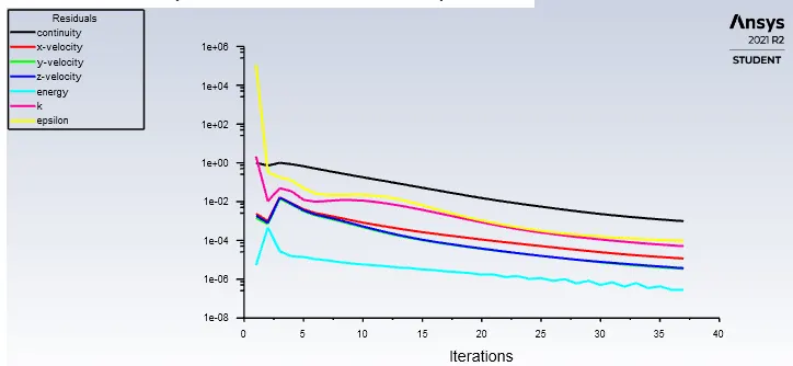
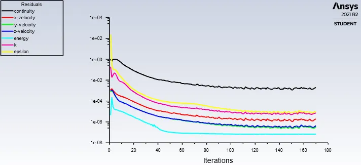
Fig.23 Residual Vs iteration plot ( inlet velocity 5m/s) Fig.23 Residual Vs iteration plot ( inlet velocity 5m/s)
refined mesh(485578)
| Velocity(m/s) |
surface heat transfer coefficient(w/m^2k) |
wall heat transfer coefficient(w/m^2k) |
Max. temperature at processor(K) |
| 1 | 13.09 | 235.14 | 1166.65 |
| 3 | 42 | 272.16 | 743.28 |
| 5 | 45.49 | 241.61 | 631.58 |
| refined(5 (m/s)) | 51.788 | 291.319 | 630.61 |
CONCLUSION
- The heat transfer coefficient increases as the inlet velocity increases.
- The maximum temperature attained by the processor reduces as the refinement of mesh and inlet velocity takes place.
- The refinement of mesh does not impact much as compared to velocity increase.
- Better cooling is observed when velocity is maximum i.e, at 5m/s .
- The project can be analysed by taking k-omega turbulence model for further analysis.