Week 6 - CHT Analysis on a Graphics card
AIM:- Perform a steady-state conjugate heat transfer analysis on a model of a graphics card.
OBJECTIVE:-
- Run the simulation for best possible mesh with combination of coarse and refined mesh in different regions by varying the velocity from 1, 2.5, and 10 m/sec.
- To find out the maximum temperature and heat transfer coefficient attained by the processor.
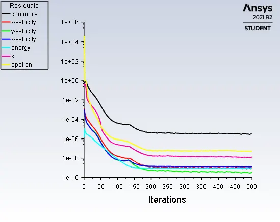
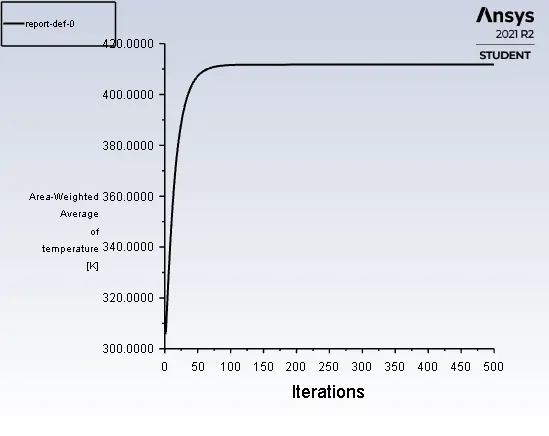
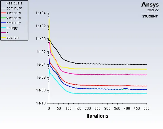
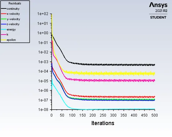
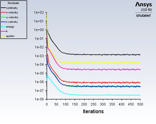
- To show that the simulation has achieved convergence with appropriate images and plots.
- To Identify potential hotspots on the model.
Contents:-
- Concept of Conjugate Heat transfer analysis on Graphic card.
- What is Graphic Card.
- Modelling and Solving Approach.
- Results of all 4 cases.
- Conclusion.
1. Concept of Conjugate Heat transfer analysis.
The Conjugate Heat Transfer (CHT) analysis type allows for the simulation of heat transfer between solid and fluid domains by exchanging thermal energy at the interfaces between them. In solids, conduction often dominates whereas in fluids, convection usually dominates. Conjugate heat transfer is observed in many situations. For example, heat sinks are optimized to combine heat transfer by conduction in the heat sink with the convection in the surrounding fluid.
Heat Transfer in Solids - In most cases, heat Transfer in fluids due to conduction that is described by Foureris law defining the conductive heat flux, q, proportional to the temperature gradients: 
Heat Transfer in Fluids - In most cases, heat Transfer in fluids due to convection that is described by Newton's law of cooling defining heat flux, q, proportional to the temperature difference: 
2. What is Graphic Card
A graphics card (also called a video card, display card, graphics adapter, or display adapter) is an expansion card which generates a feed of output images to a display device (such as a computer monitor). Frequently, these are advertised as discrete or dedicated graphics cards, emphasizing the distinction between these and integrated graphics. At the core of both is the graphics processing unit (GPU), which is the main part that does the actual computations, but should not be confused with the graphics card as a whole, although "GPU" is often used as a metonymic shorthand to refer to graphics cards.
Most graphics cards are not limited to simple display output. Their integrated graphics processor can perform additional processing, removing this task from the central processor of the computer. For example, Nvidia and AMD (previously ATI) produced cards that render the graphics pipelines OpenGL and DirectX on the hardware level. In the later 2010s, there has also been a tendency to use the computing capabilities of the graphics processor to solve non-graphic tasks, which can be done through the use of OpenCL and CUDA. Graphics cards are used extensively for AI training, cryptocurrency mining and molecular simulation.
Usually, the graphics card is made in the form of a printed circuit board (expansion board) and inserted into an expansion slot, universal or specialized (AGP, PCI Express). Some have been made using dedicated enclosures, which are connected to the computer via a docking station or a cable. These are known as eGPUs.
3. Modelling and Solving Approach.
Geometry:-
- In this study we use the Graphic card model first we have to load the graphic card model in the spaceclaim.
- After imported the geometry, Geometry is inside the Enclosure. In order to view the Graphic card Geometry First we have to hide the Enclosure part.
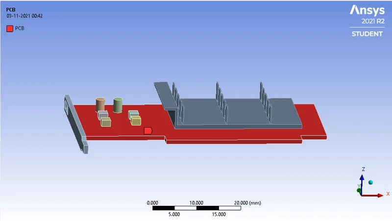
- The Geometry Consists of 4 parts:-
- Enclosure
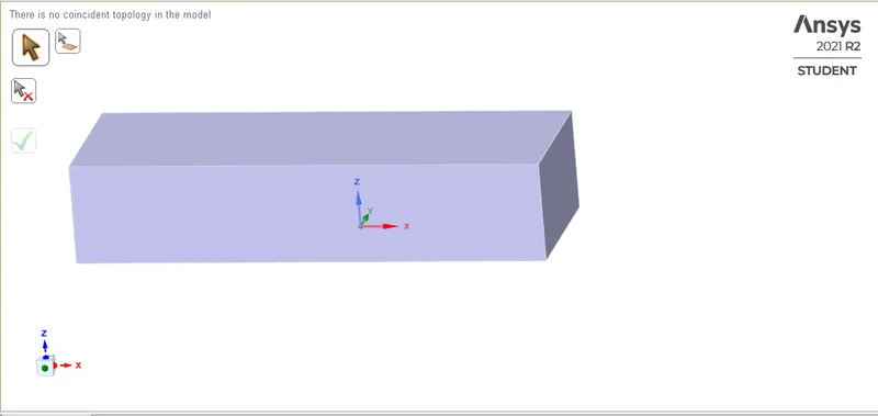
2. Printed-circuit-board (PCB) - Base of the Graphic card.
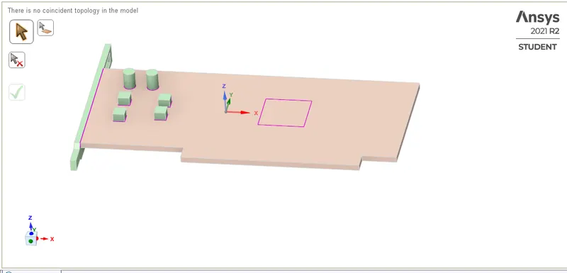
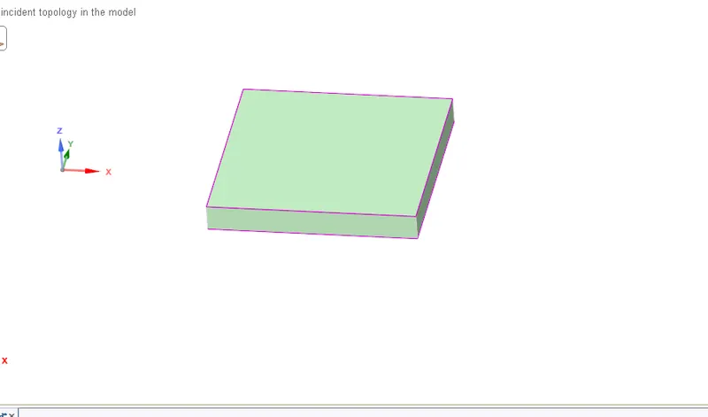
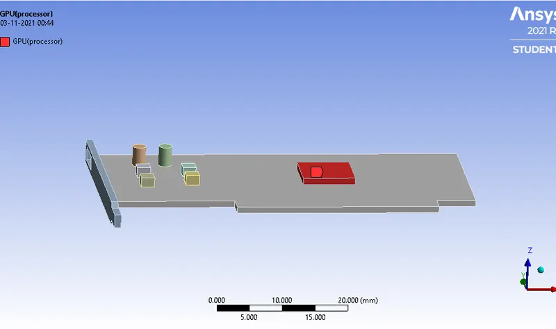
3. Processor - Heat Source.
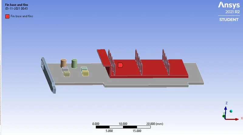
4. Fin base and fins - Extended surface for the heat dissipation.
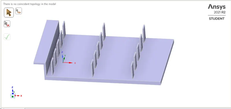
- We need to check the interfaces of the geometry If there is Interfaces It will generates Non-confirmal meshes and It will lead to the wrong results.
- For the confirmal meshes We have to ON the Share-topology GO to workbench and select the Whole body and Click on the Shareprep then click on Ok.
- It will shows the pink Outlines on the Interfaces of the solid bodies It means the Interfaces of the solid bodes are shared.
Meshing:-
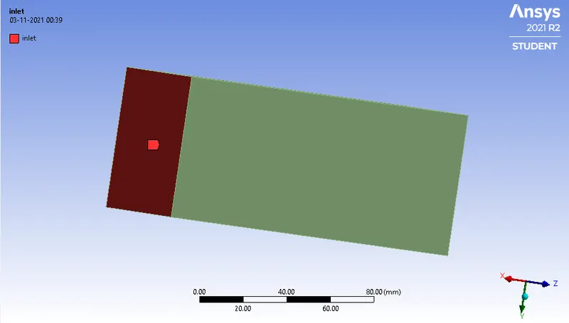
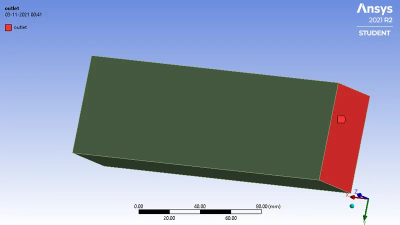
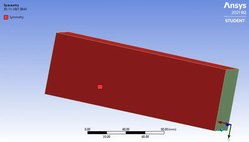
- First we have to select the surface Or body and named it Named selection as
Inlet
Outlet
Symmetry
PCB(Base)
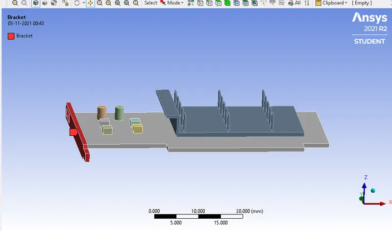
Brackets
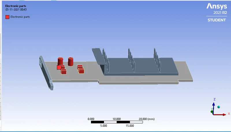
Electronic components
Processor
Fin Base and Fins
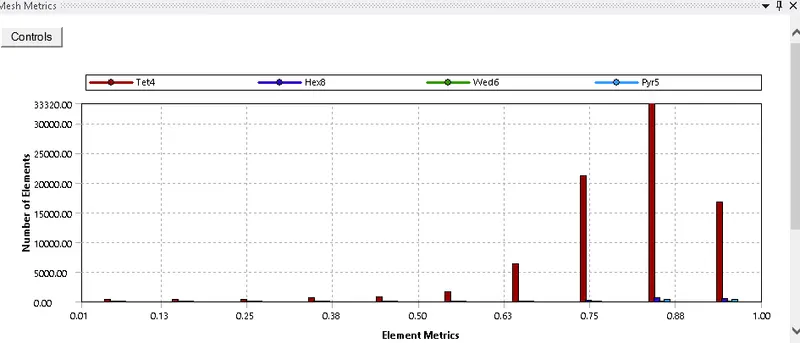
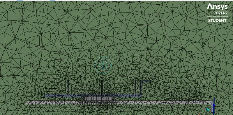
For Baseline Mesh SetUp:-

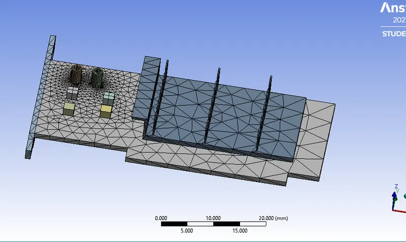
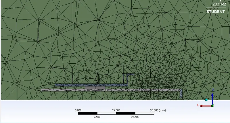
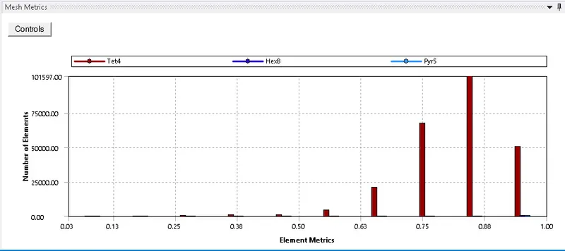
Element Quality
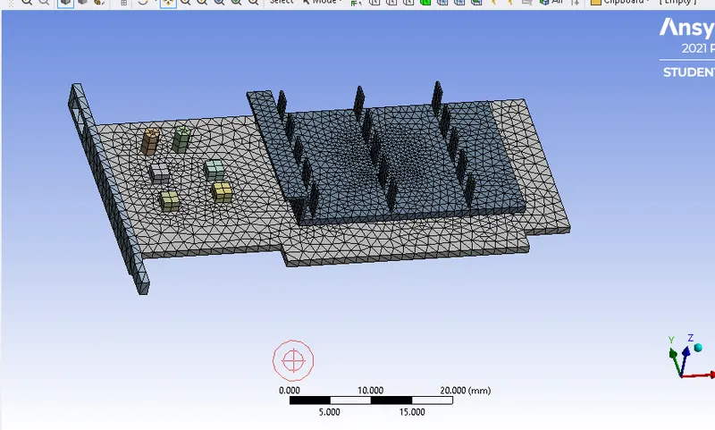
For Refine Mesh Setup:-
For Refine the Graphic card and Enclosure
- Face sizing - On Enclosure, Element size = 5mm
- body sizing - PCB(Base) - Element size = 1.5mm
- body sizing - Electronic Components - Element size = 1.5mm
- body sizing - Fins and Fin base - Element size = 1.5mm
- body sizing - Processor - Element size = 1.5mm

Element Quality
Here, is the Refined Mesh to capture the accurate Results of Surface Heat transfer coefficient and Temperature on the Processor.
Setup Fluent (pre-processing)
- Solver - Pressure-based, Velocity Formulation - Absolute and Time - Steady
- Turbulnce Model - K epsilon and Energy option is ON for Temperature
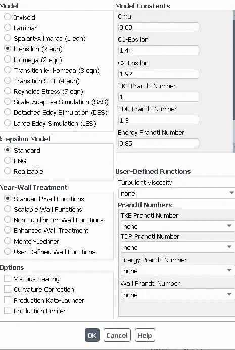
- Material Selection settings For Enclosure and Graphic card.
- for the Fluid - Air is Used as Fluent In the Enclosure.
- For the Brackets Solid material is Used - Steel.
- For Printed circuit board (PCB) - Wood Because it has low thermal conductivity K = 0.173 W/mK and we want heat conducted by the fins and Fin base More which is produced by the Processor.
- So, For Fins and fin base - Copper high thermal conductivity material K = 387.6 W/mK is used.
- For Processor and Electronic Components we use - Silicon.
Fluid - air
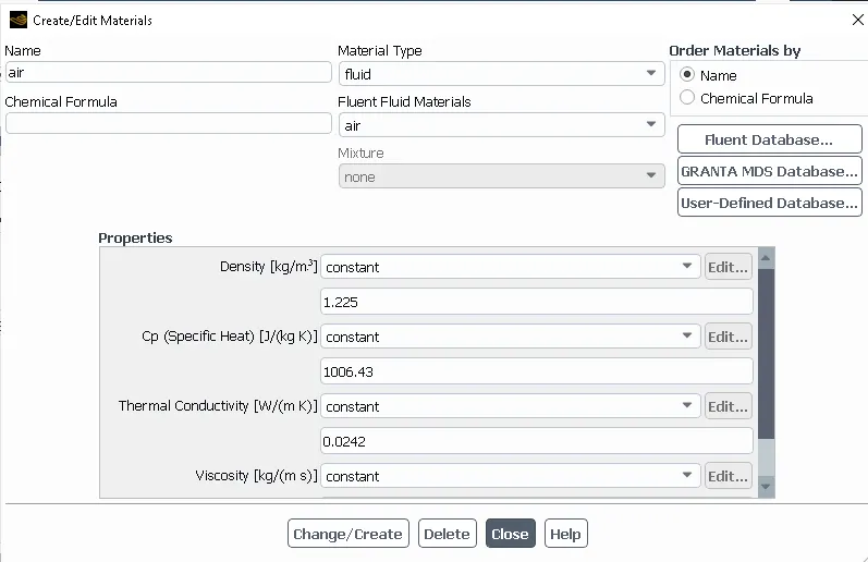
Solids - Copper, Steel, Silicon and Wood
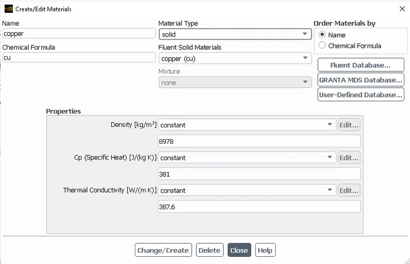
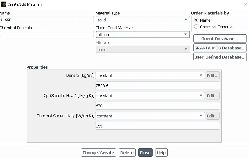
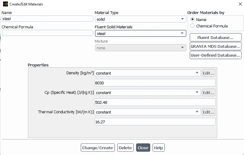
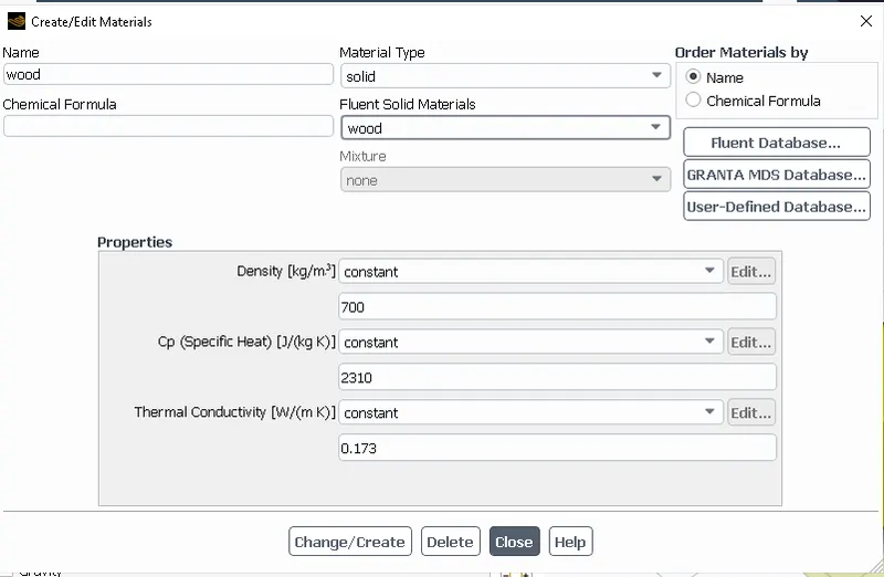
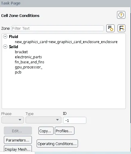
- Cell Zone Conditions Setup to provide the information to Fluent that in enclosure we are using Air as Fluid and For the Graphic card Solid Materials used different-different as per the parts of the Graphic card.
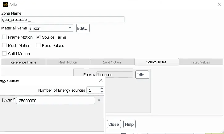
After Provide the details of the Fluid and Solid Materials We Provide the source terms to the Processor means We are providing the Heat source value to the Processor.
Let us Assume Thermal design Power (TDP) for the Graphic card = 8 Watt.
Hence, the Heat generated per volume by the Processor or GPU = `(TDP)/(Volume of GPU)`
Voume of Processor = 64e-9
Heat Generated = `(8)/(64e-9)`
Heat Generated = 125e6 W/m^3
- Boundary Conditions Setup:-
Here, is 4 cases at velocity Inlet:-
Case1 : Velocity at Inlet is 1 m/s
Case2 : Velocity at Inlet is 2.5 m/s
Case3 : Velocity at Inlet is 5 m/s
Case4 : Velocity at Inlet is 10 m/s
Outlet: as Pressure-Outlet as 0 pa.
Walls - Symmetry.
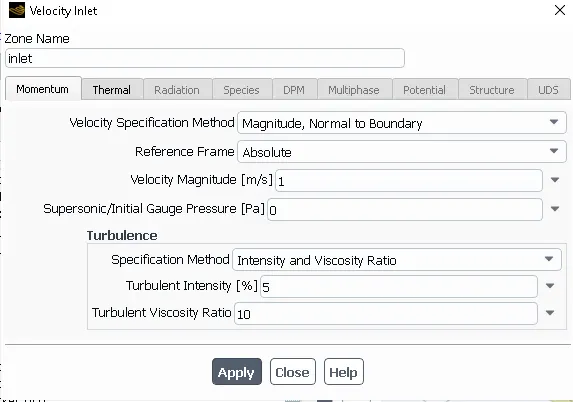
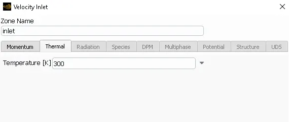
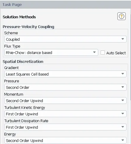
- Solution Method we used as shown below.
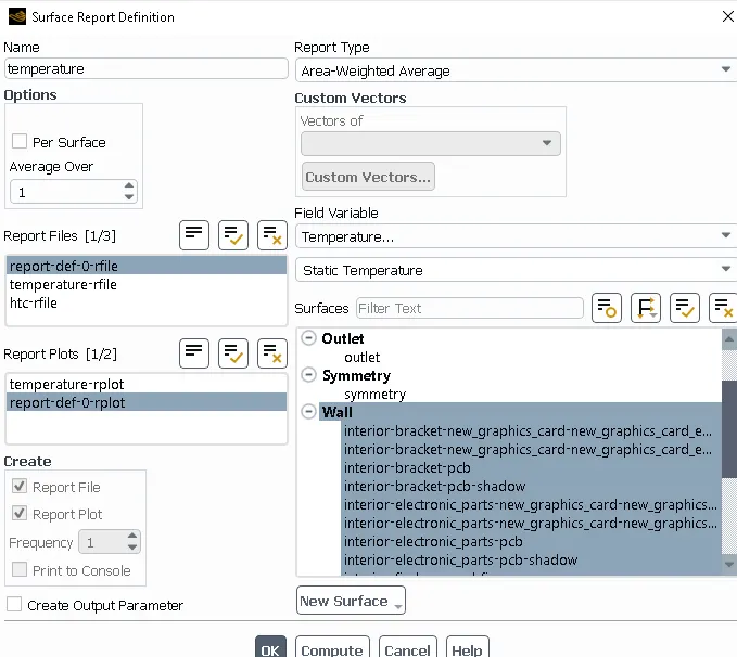
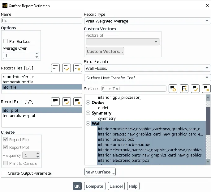
- Temperature and heat transfer coeffcient report setup.
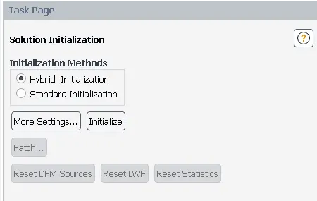
- Hybrid Initilalization.
- After Initialization creates the contours of temperature.
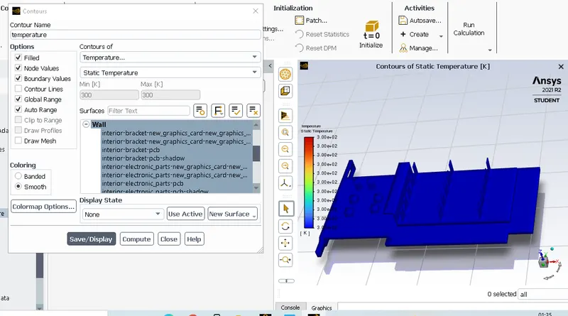
After the Setup go to calculations > the no. of iterations provided as 500 > Then Hit calculate. After run the simulation almost 500 Iterations here are the results.
Results:-
Case1 : Baseline Mesh
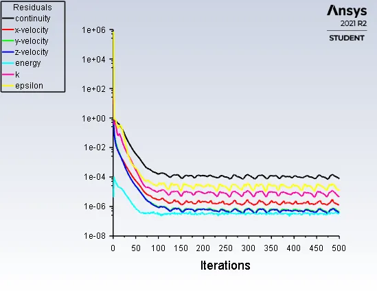
Residual plot
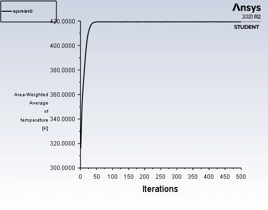
Area-weighted Average of temperature
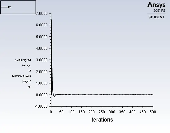
Heat-Transfer Coefficient plot
Temperature contours
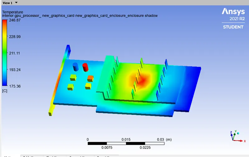
- From the above contours we can clearly see that the temperature we have given at inlet is 300 k and the and Max. temperature at the Top of the processor is about 520.99K
- At the Fins and the entire components the temperature is increasing due to heat is dissipating from the heat source to the base and then to the fins.
Heat attained by the processor
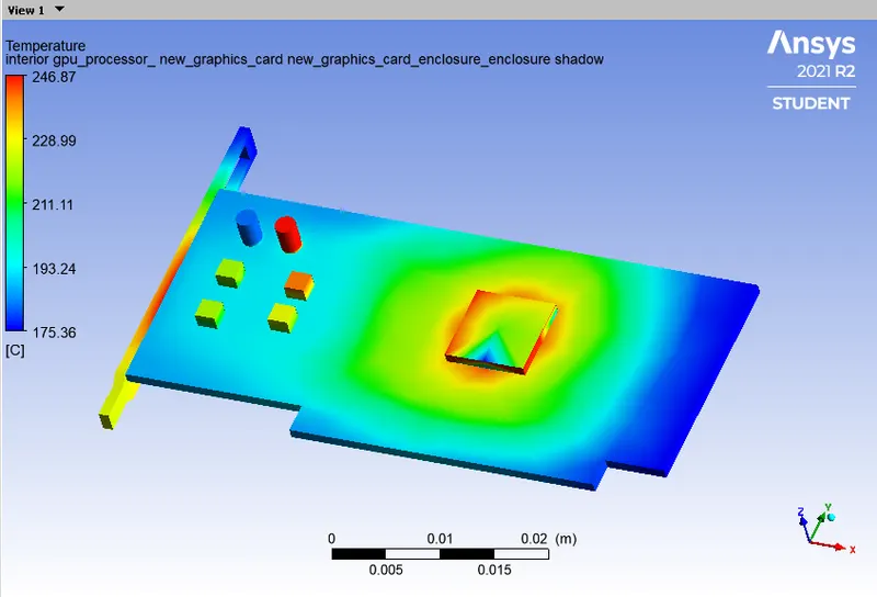
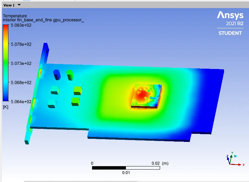
- The maximum heat is attained by the processor bcoz it is the heat source and power is generated is about 125e6 W/m^3.
- The material is selected for the processor is Silicone which has more conductivity which can happen heat transfer is more quickly to the other parts of the graphic card.
Temperature contours in plane
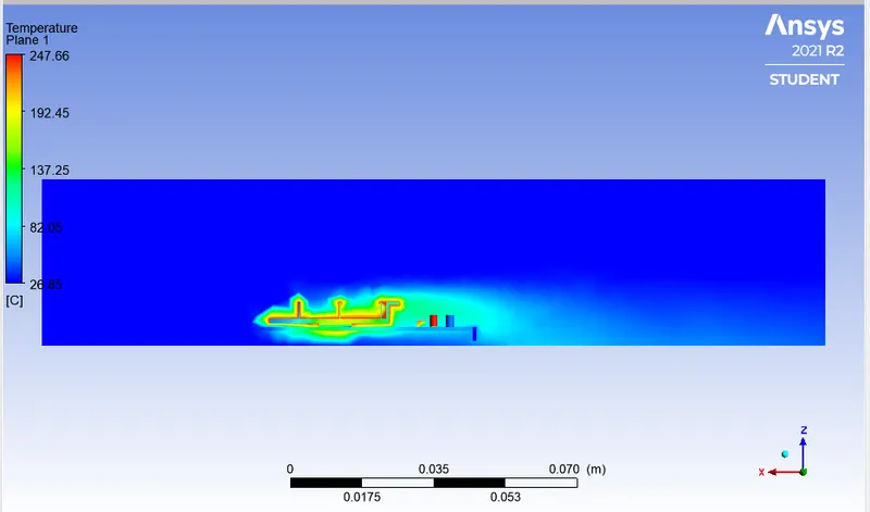
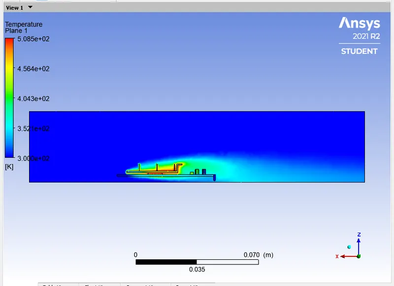
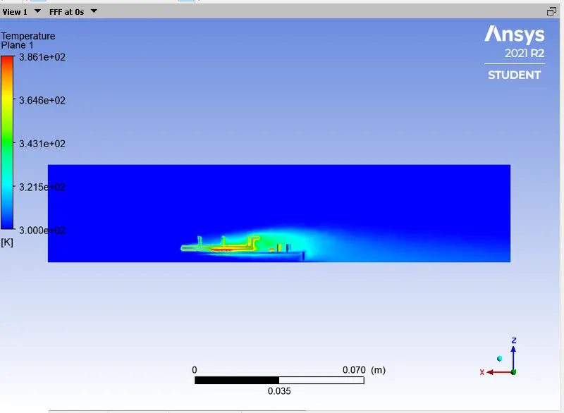
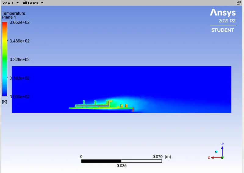
The temperature has given at the Inlet is about 300K and temperture rises due to heat is being generated inside the processor the temperature goes upto 520K.
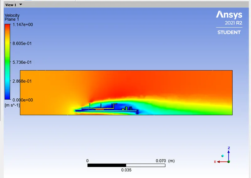
Velocity contours in plane
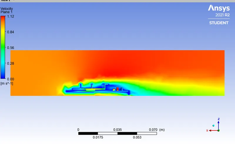
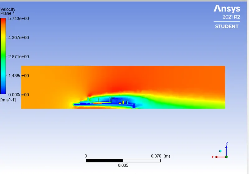
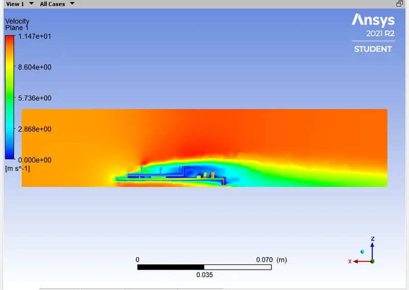
- The inlet velocity has given in this case is 1 m/sec and the velocity get hits on the edges thats why at that position velocity is decreased.
- After the flow hits the fins, th pressure is dropped and velocity starts to increase.
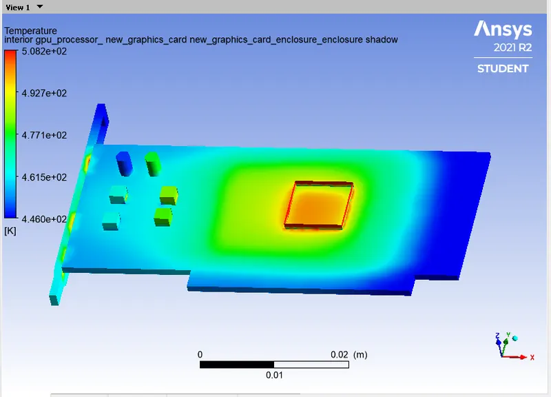
Hotspots
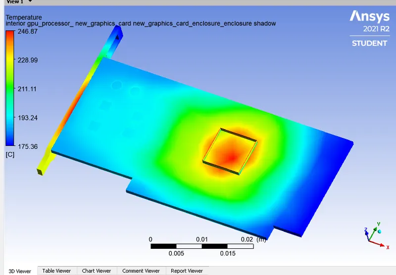
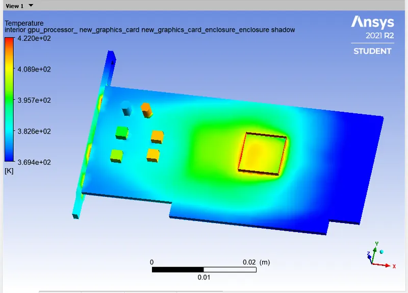
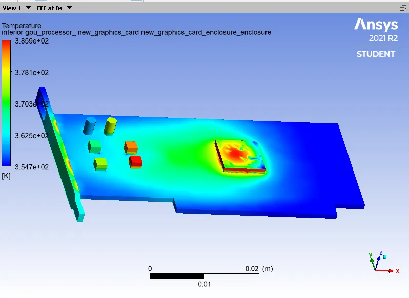
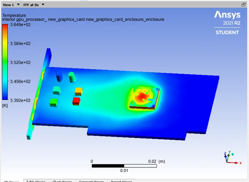
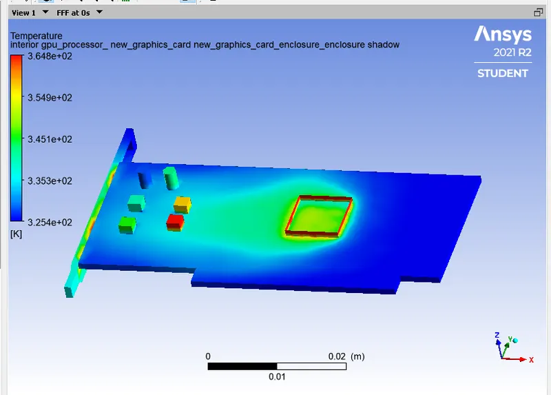
It is the contour plots of the heat spots In this figure you can easily see the heat is more on the processor, then the base of fin and fins because heat is generated on the processor.
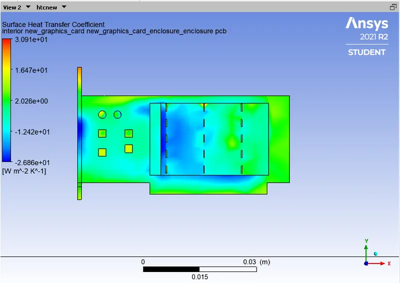
Surface heat transfer coefficient
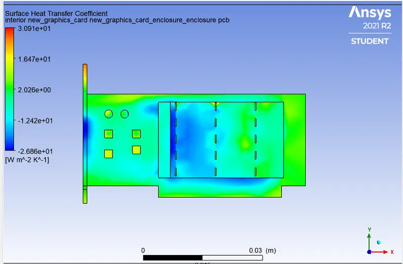
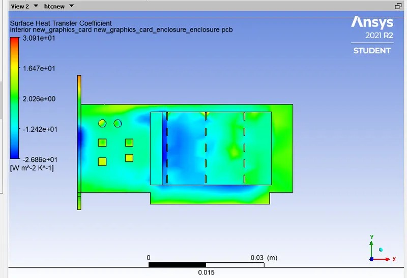
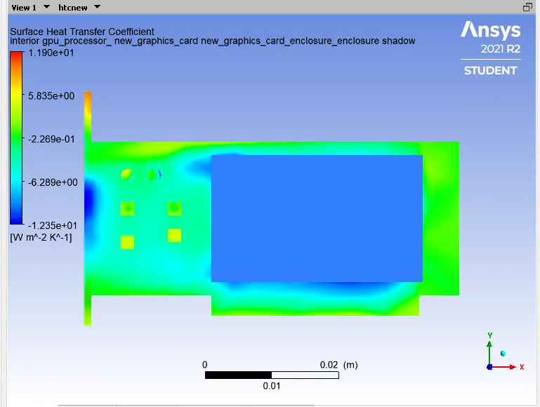
- here, you can see the maximum heat transfer coefficent on the fins and fin base is more because It is high conductive material and heat is transfer here is more.
- At the symmtery walls of the domain the heat transfer coeffcient is less as compared to the graphic card parts.
Case2: Refined Mesh
Inlet Velocity 1 m/s and the Inlet Temperature is 300K
Residual plot
Area-weighted Average of temperature
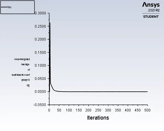
Heat-Transfer Coefficient plot
Temperature contours
Heat attained by the processor
Temperature contours in plane
Velocity contours in plane
Hotspots
Surface heat transfer coefficient
Case3: Refined mesh with Velocity =2.5m/s
Residual plot
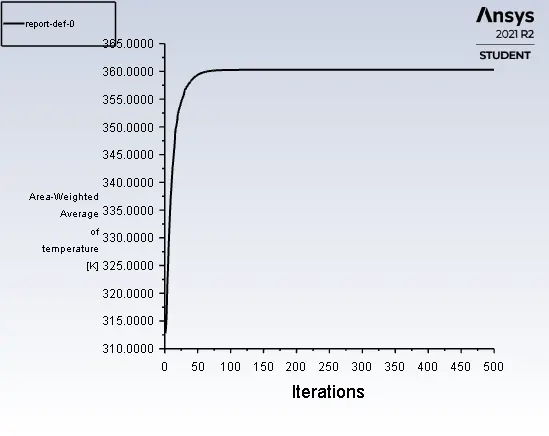
Area-weighted Average of temperature
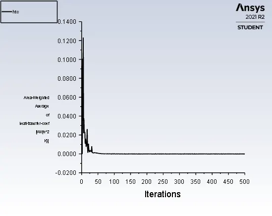
Heat-Transfer Coefficient plot
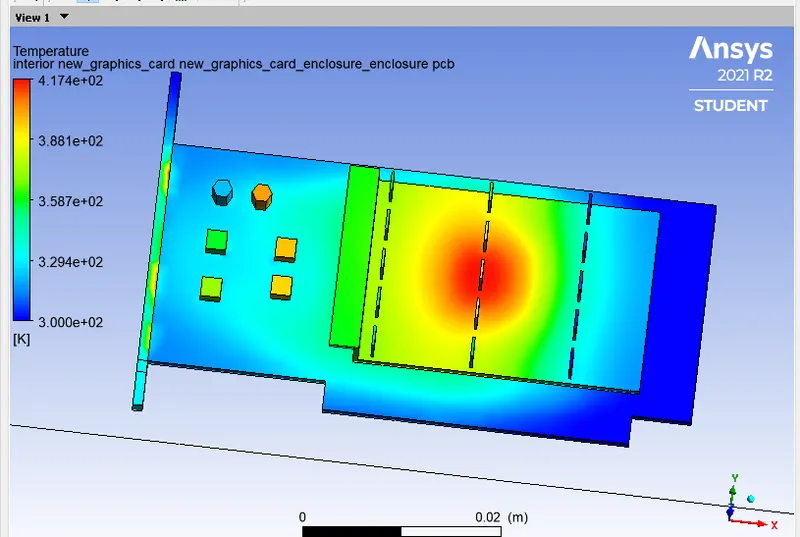
Temperature contours
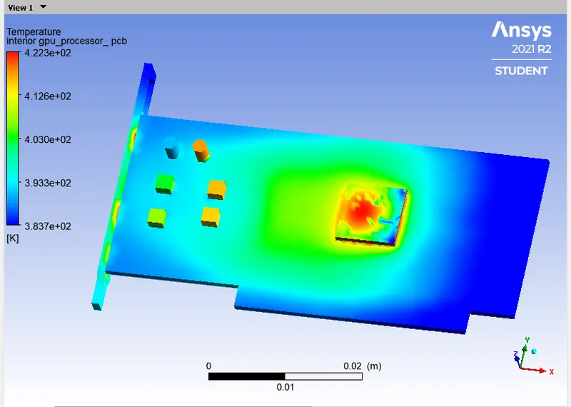
Heat attained by the processor
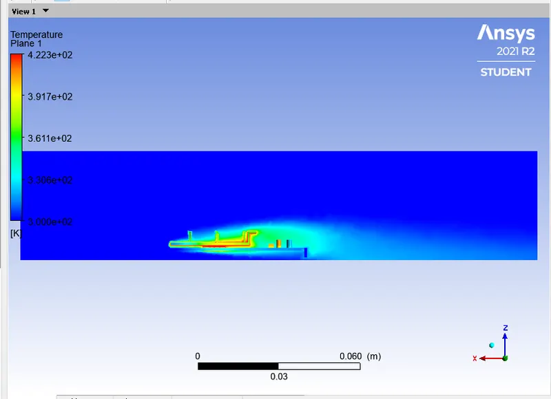
Temperature contours in plane
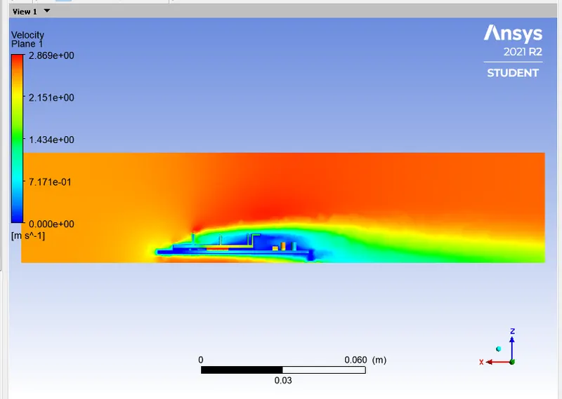
Velocity contours in plane
Hotspots
Surface heat transfer coefficient
Case4: Refined mesh with Velocity =5m/s
Residual plot
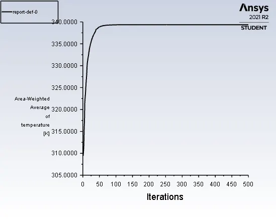
Area-weighted Average of temperature
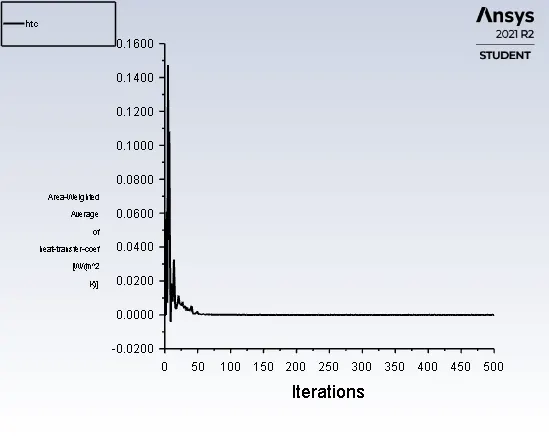
Heat-Transfer Coefficient plot
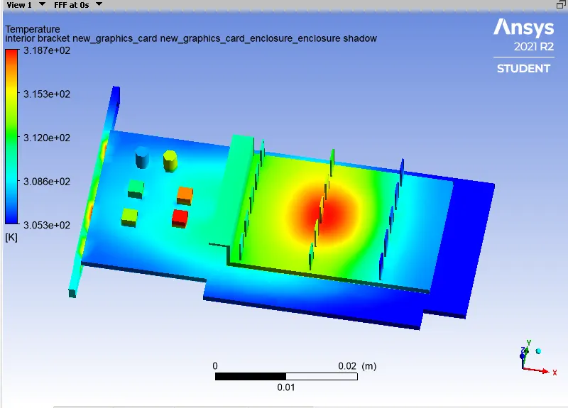
Temperature contours
Heat attained by the processor
Temperature contours in plane
Velocity contours in plane
Hotspots
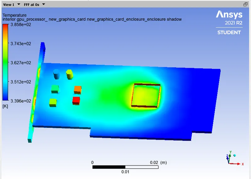
Surface heat transfer coefficient
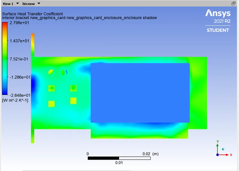
Case4: Refined mesh with Velocity =10m/s
Residual plot
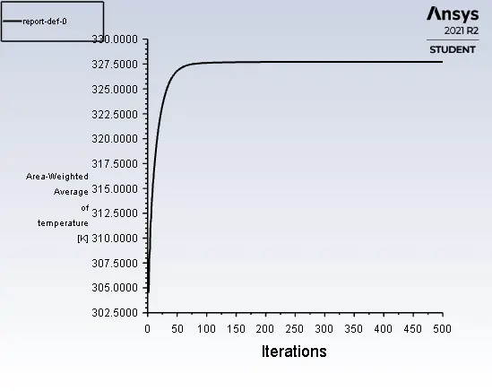
Area-weighted Average of temperature
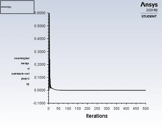
Heat-Transfer Coefficient plot
Temperature contours
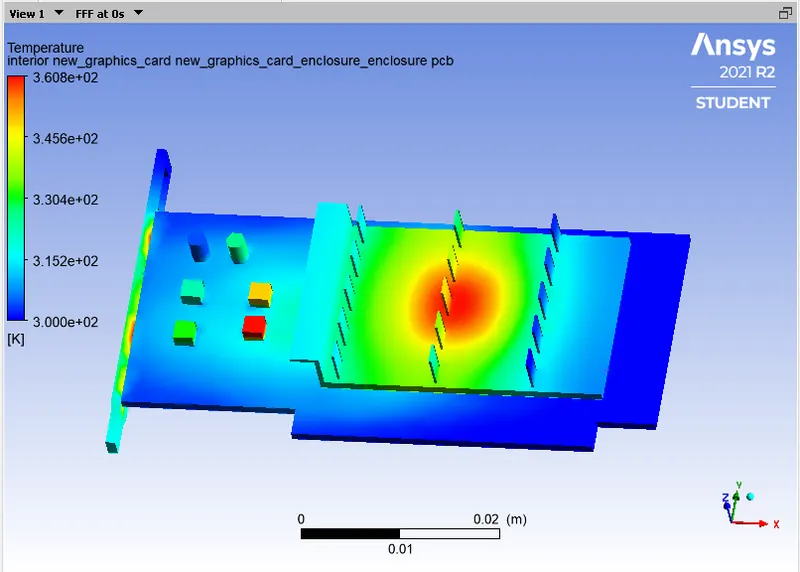
Heat attained by the processor
Temperature contours in plane
Velocity contours in plane
Hotspots
Surface heat transfer coefficient
Here, is the Table for the for all 5 cases data we got from the simulations and then we are comparing the results.
Comparison between the all 5 cases and here, is the Table:-
| Parameters | No. of Elements | No. of Cases | Max. Temperature (K) | Max. Heat transfer coefficient (W/m^2K) | Avg. Temperature (K) | Avg. Heat transfer coefficient (W/m^2K) |
| Baseline Mesh | 82876 | Case no. 1 | 520.996 | 520.46 | 419.28 | 0.0056 |
| Refined Mesh | 247811 | Case no. 2 | 508 | 1085 | 411.74 | 1.710 |
| Refined Mesh | 247811 | Case no. 3 | 422 | 1787.50 | 360.276 | 1.819 |
| Refined Mesh | 247811 | Case no. 4 | 386.17 | 2389.23 | 339.35 | 8.60 |
| Refined Mesh | 247811 | Case no. 5 | 327 | 2580.96 | 309 | 10.56 |
Conclusion:-
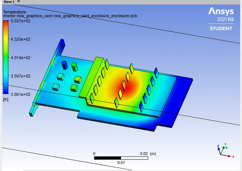
The maximum temperature in the baseline mesh we got is about 520K and In the refined mesh we got maximum temperature is 508K. As you see when you increase the Velocity we got the decreased temperture as shown in the given below figure.
It is due to Increase in velocity faciliates the rate of heat transfer by convection and It promotes cooling of the electronic components and the whole grahic card. With an increase in velocity, we saw considerable drop in temperature and substantial rise in heat transfer coefficient which shows effective mode of heat dissipation. From the temperature distributions, we can see hotspots in the fins and the base also near the processor surface based on thermal conductivity It is distributed accordingly. The high temperature zone is fins and fin base.
The hotspots is got by these simulations in the graphic card as shown above in the figures It is due to the heat generation by the Processor. As in whole graphic card predominated hotspot is Processor.
Here, is the animation link of how CHT analysis on graphic card takes place for baseline Mesh:-