Week 6 - CHT Analysis on a Graphics card
AIM:
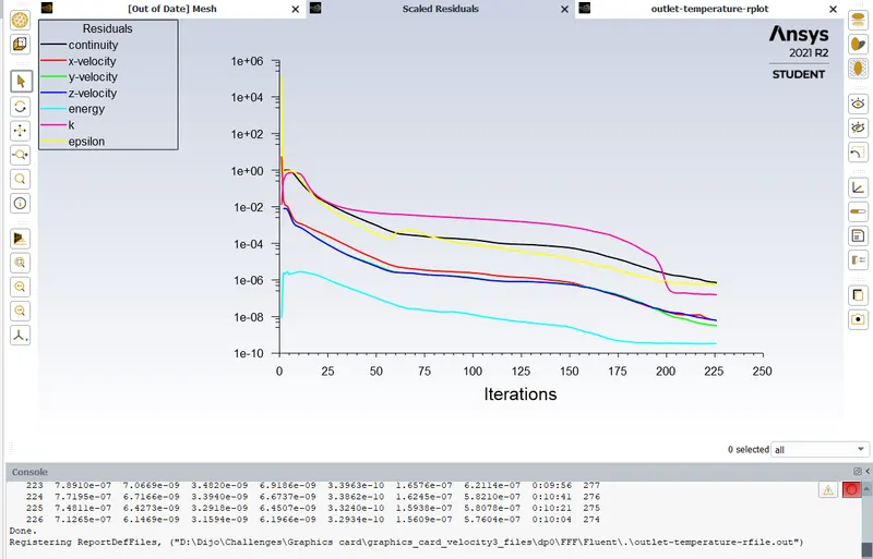
To conduct a steady state conjugate heat transfer analysis on a graphics card model using ANSYS Fluent.
Theory:
In CFD, Conjugate Heat Transfer (CHT) analysis allows users to do simulation of heat transfer between solid and fluid domains. Heat transfer happens between a soild and fluid by exchanging thermal energy at the interfaces between them. Some examples are the simulation of heat exchangers and cooling of electronic equipment.
Solving approach:
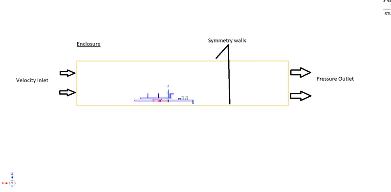
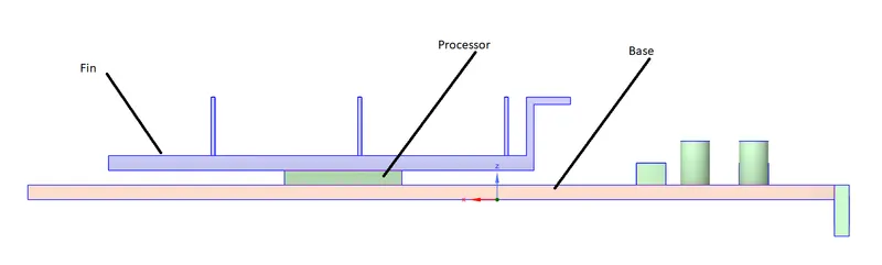
Geometry:
Solver settings:
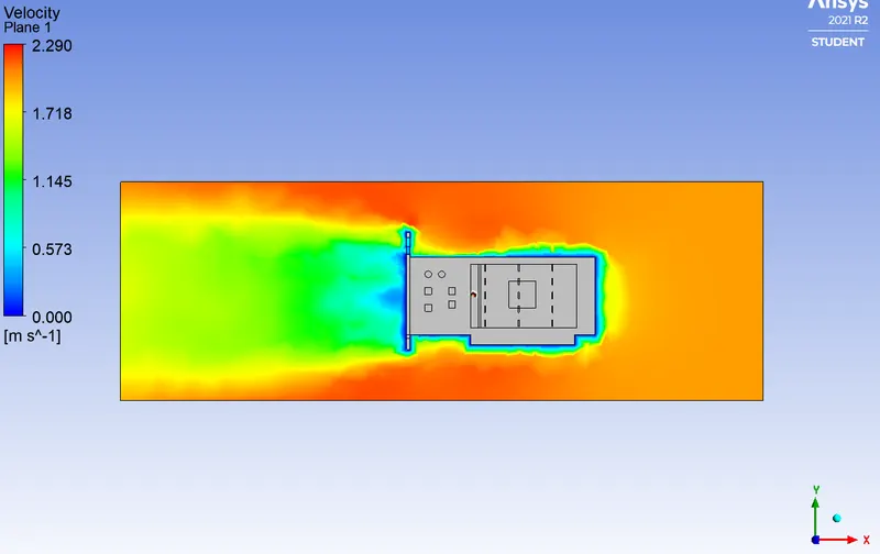
Velocity was choosen as 2m/sec.
Model Settings:
------------------------------------------------------------------
Space 3D
Time Steady
Viscous Realizable k-epsilon turbulence model
Wall Treatment Standard Wall Functions
Heat Transfer Enabled
Material Properties:
-------------------
1. pcb -- FR4
FR4 is the most used material in manufacturing PCB.
FR4 is a standard given by the National Electrical Manufacturers Association. It is a glass-reinforced epoxy resin laminate. FR means "flame retardant" and it means that the material is compliant with the UL94V-0 standard on plastic material flammability.
Density kg/m^3 constant 1850
Cp (Specific Heat) J/(kg K) constant 1100
Thermal Conductivity W/(m K) constant 0.29
2. processor - Silicon
Density kg/m^3 constant 2000
Cp (Specific Heat) J/(kg K) constant 710
Thermal Conductivity W/(m K) constant 150
3. Fin - Aluminium
Fins must be metallic to conduct heat easily and light weight.
Density kg/m^3 constant 2719
Cp (Specific Heat) J/(kg K) constant 871
Thermal Conductivity W/(m K) constant 202.4
4. air (fluid)
Density kg/m^3 constant 1.225
Cp (Specific Heat) J/(kg K) constant 1006.43
Thermal Conductivity W/(m K) constant 0.0242
Viscosity kg/(m s) constant 1.7894e-05
Cell Zone Conditions
--------------------
processor - solid
fin - solid
base - solid
enclosure - fluid
Setup Conditions
processor
Condition Value
---------------------------------------------------------------------------------------
Material Name processor
Specify source terms? yes
Source Terms ((energy ((constant . 156250000) (inactive . #f) (profile ))))
Frame Motion? no
Boundary Conditions
-------------------
Zones
interior-enclosure-processor-shadow 22 wall
interior-enclosure-processor 3 wall
interior-enclosure-fin-shadow 21 wall
interior-enclosure-fin 4 wall
interior-fin-processor-shadow 20 wall
interior-fin-processor 2 wall
interior-base-processor-shadow 19 wall
interior-base-processor 5 wall
interior-base-enclosure-shadow 11 wall
interior-base-enclosure 1 wall
inlet 16 velocity-inlet
outlet 17 pressure-outlet
symmetry 18 symmetry
inlet
Velocity Magnitude [m/s] 2
Equation Solved
-------------------
Flow yes
Turbulence yes
Energy yes
Pressure-Velocity Coupling
Type Coupled
Pseudo Transient yes
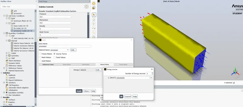
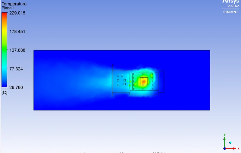
Power =10W
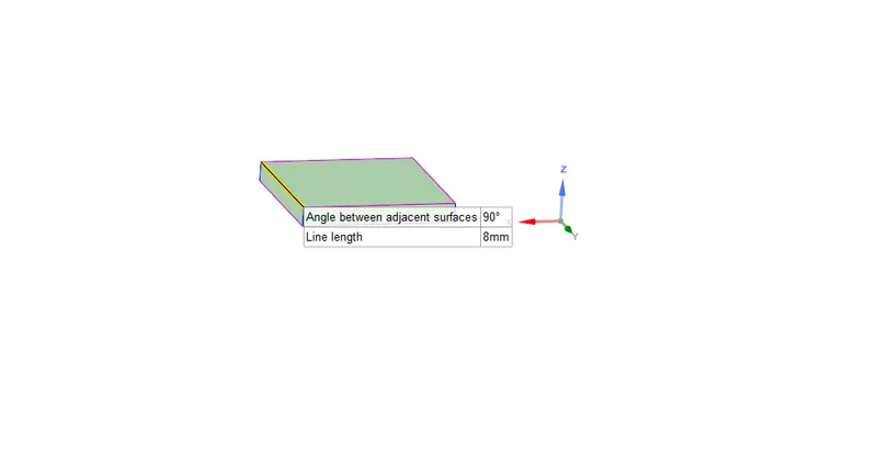
Heat generated = 10W/64mm^3
CASE 2:
Inlet velocity 3m/sec
Power 2W
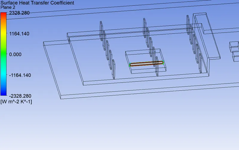
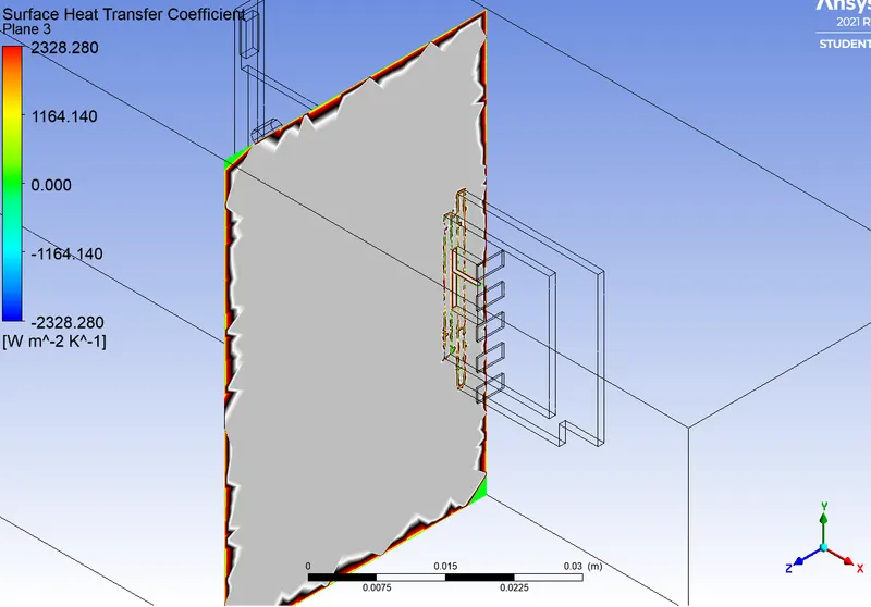
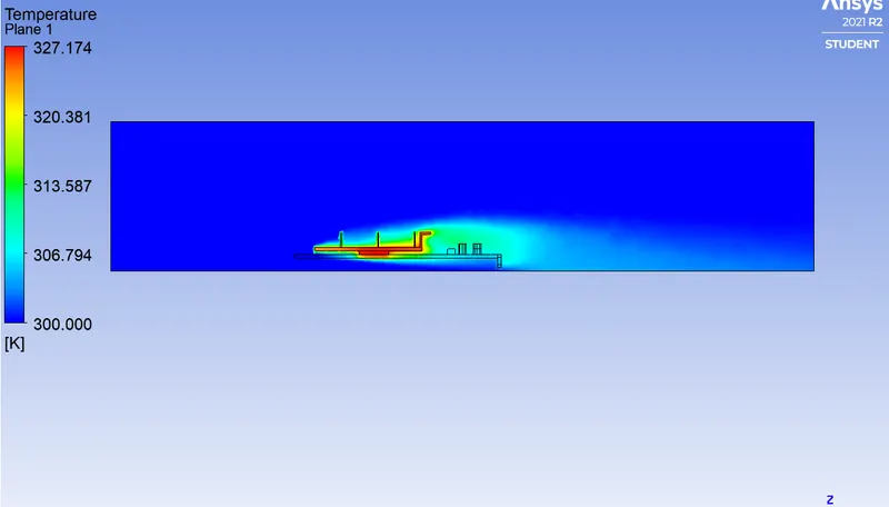
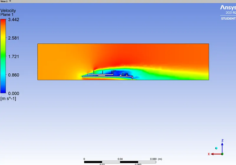
CASE 3:
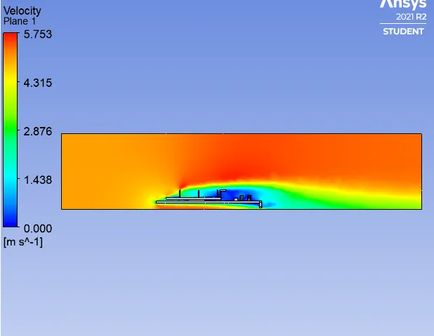
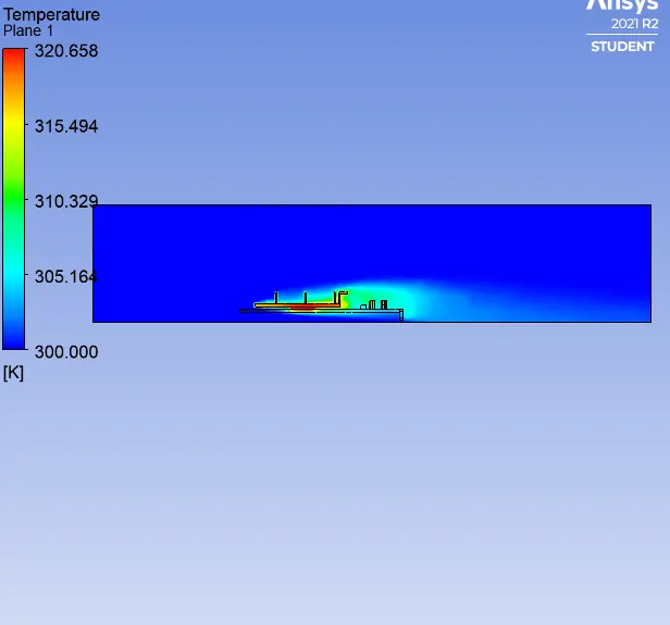
For first case Power was choosen as 10W and the maximum temperature on the processor was obtained as 229 degreeC. It is a high temperature for processor and is not recommended.
It is suggested to use power value as 1 or 2 watts.
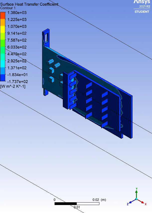
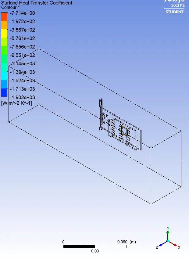
Also while selecting reference values, give inlet area as area of the inlet of enclosure.