Week 6 - CHT Analysis on a Graphics card
Aim:
To perform a steady-state conjugate heat transfer analysis on a model of a graphics card with explaination the reason for choosing a particular mesh settings.
Objectives:
- Run the simulation by varying the velocity from 1m/sec to 5m/sec for at least 3 velocities and discuss the results.
- Find out the maximum temperature and heat transfer coefficient attained by the processor.
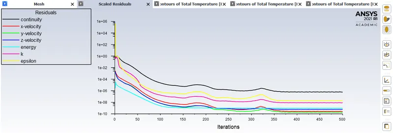
- Prove that the simulation has achieved convergence with appropriate images and plots.
- Identify potential hotspots on the model.
NOTE:
Can use appropriate materials for the simulation.
Make sure to properly define the correct solid and fluid zones.
Graphics card:
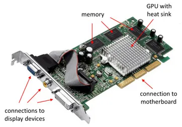
According to NVIDIA, the standard operating temperature of a graphics processing unit (GPU) is 104°F to 194°F (40°C to 90°C). Since room temperature is 68°F (20°C), your GPU will always be and feel warm or hot while operating at any given time.
However, your GPU should not get too hot.
Five integral hardware components in desktop computers and laptops generate substantial heat.
These include:
- The central processing unit (CPU).
- Graphics processing unit (GPU).
- Heat sink.
- Motherboard components like the northbridge and southbridge chipsets.
- Hard disk drive or solid-state drive (HDD/SSD).
- The optical disc drive (ODD).
Among these, the CPU and the GPU generate the most heat.
Factors that cause higher temperatures of GPU:
- Inadequate cooling
- Dusty heat sink
- Obstructed airflow
- Dry or worn-out thermal paste
- Overclocked GPU
- Stressed GPU

Volume of processor & energy source calculation:
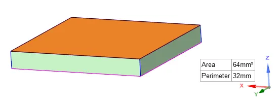
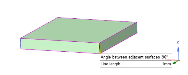
`Volume=Area*height`
`Volume=64mm^2*1mm`
`Volume=64mm^3=64*10^-9m^3=0.000000064m^3`
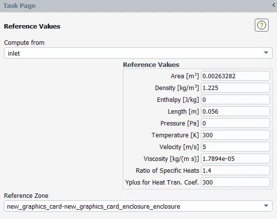
Since the model grapfics card model is a scaled down version of the original, the power consumed would be 15W.
The heat generated per unit volume is calculated for the processor.
`(15W)/(64*10^-9m^3)=234375000W/m^3`
BASELINE:
Mesh:
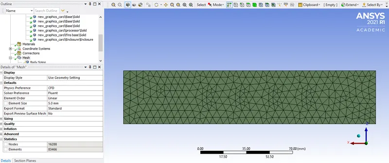
Enclosure: Mesh size = 5mm
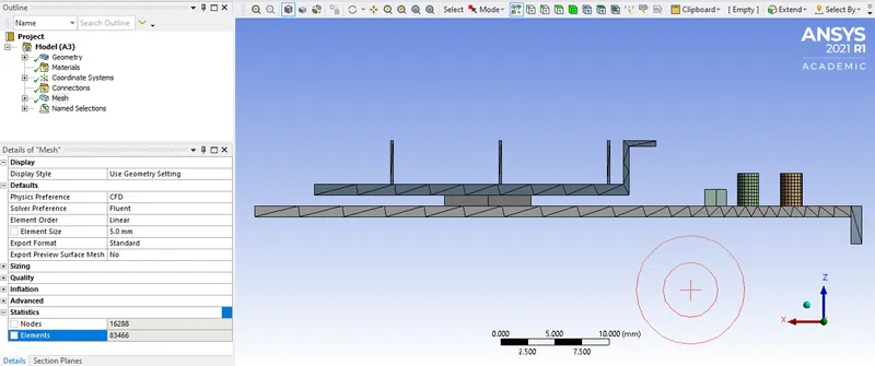
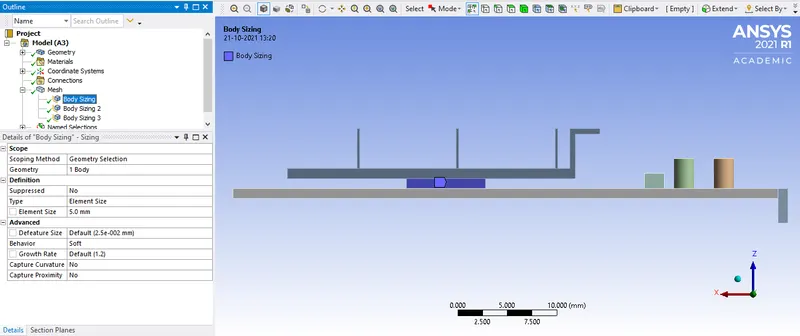
Processor: Mesh size = 5mm
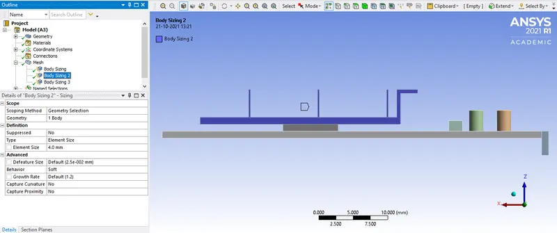
Fins: Mesh size = 4mm
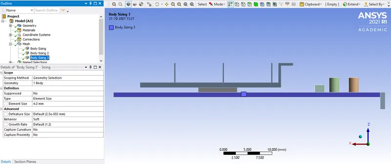
Base: Mesh size = 4mm
Setup:
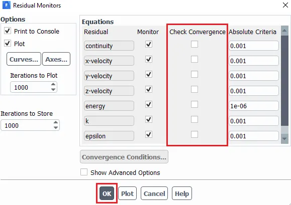
Uncheck the convergence boxes to avoid solution convergence before the intended number of iterations has been achieved.
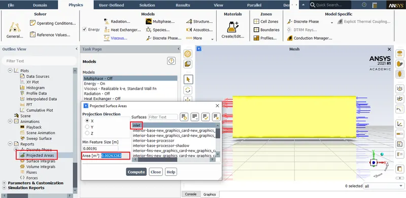
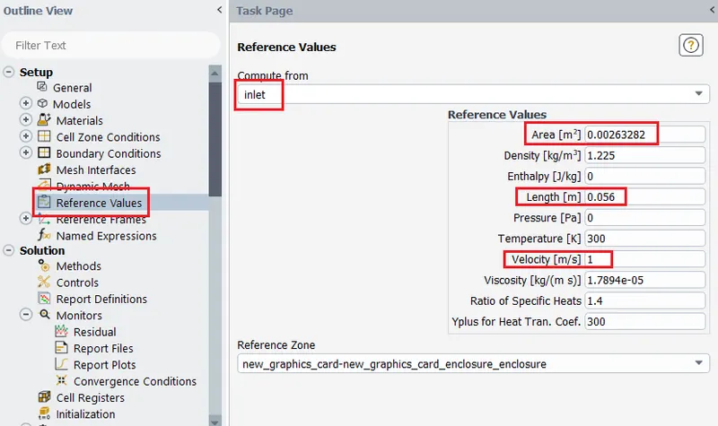
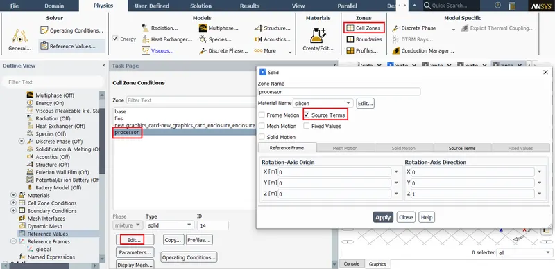
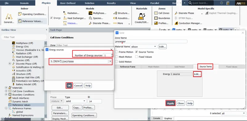
Material:
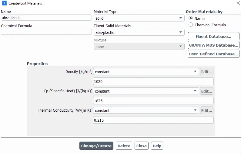
Material properties for base of GPU.
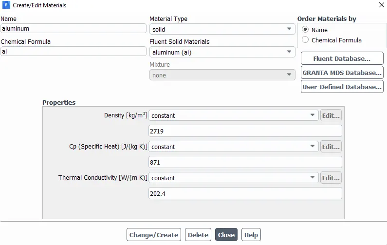
Material properties for fins of GPU.
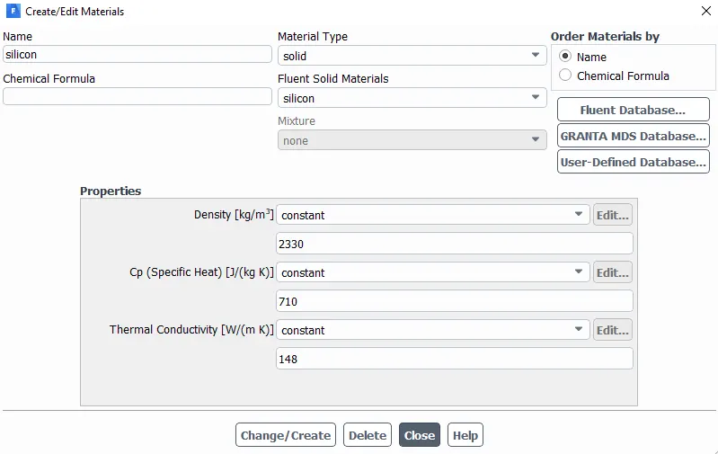
Material properties for the processor of GPU.
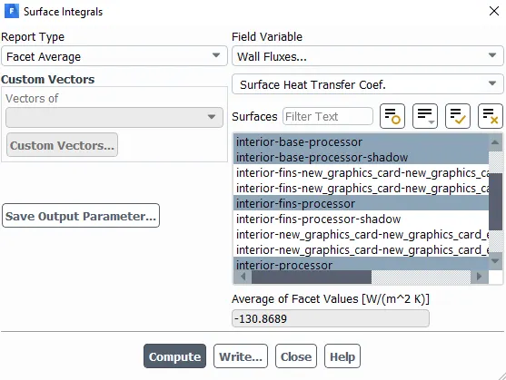
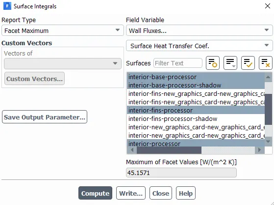
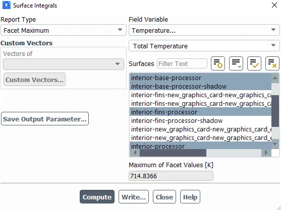
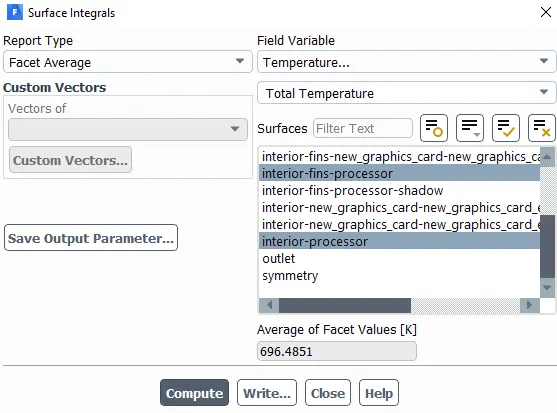
Surface integral values:
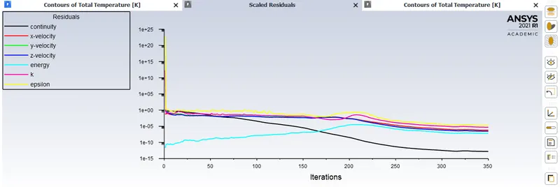
Residual plot:
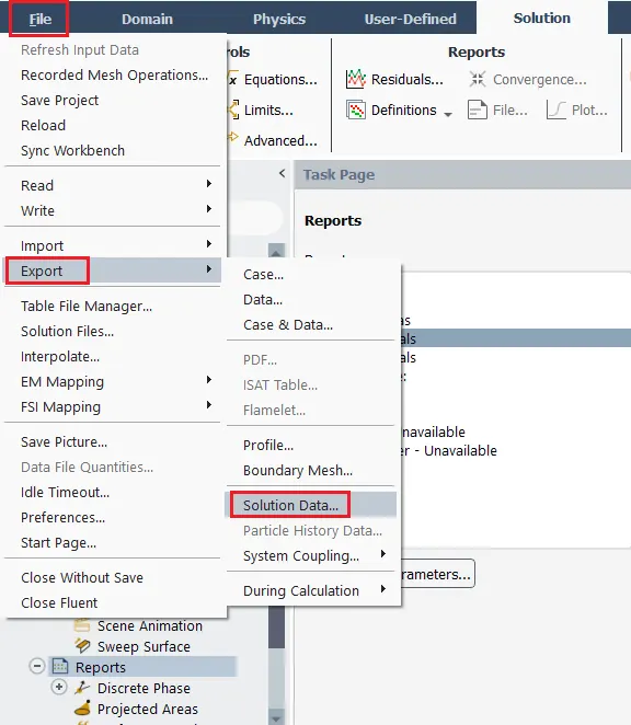
Exporting solution data:
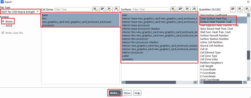
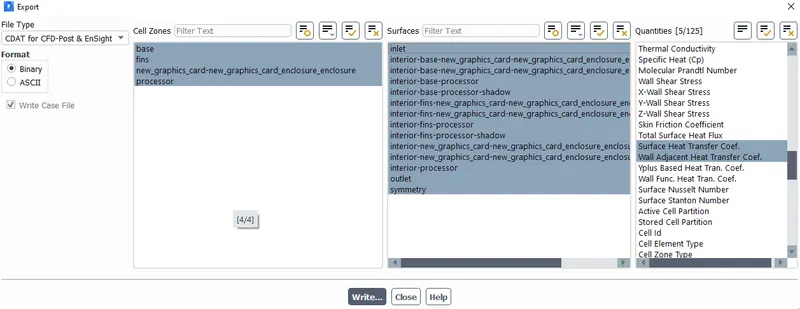
Select Total temperature, Total pressure, Velocity magnitude & Surface heat transfer coeffecient from quantities.
Post processing:
1) Temperature contours:
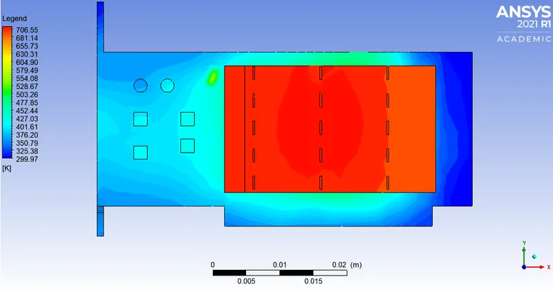
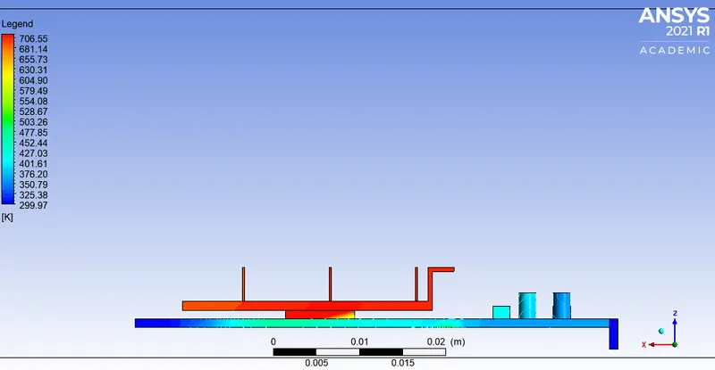
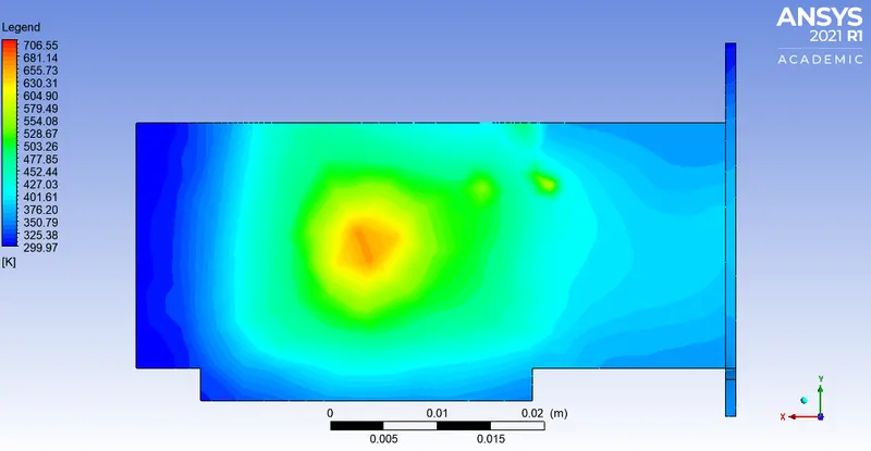
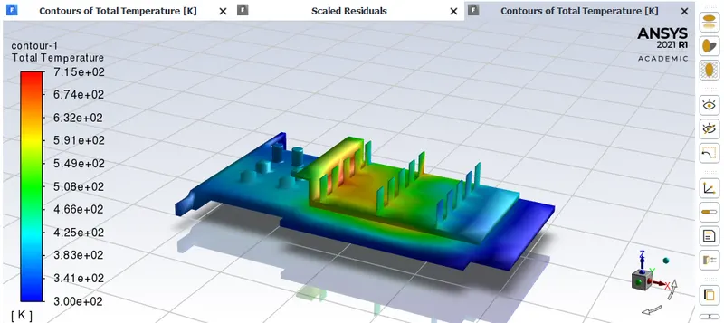
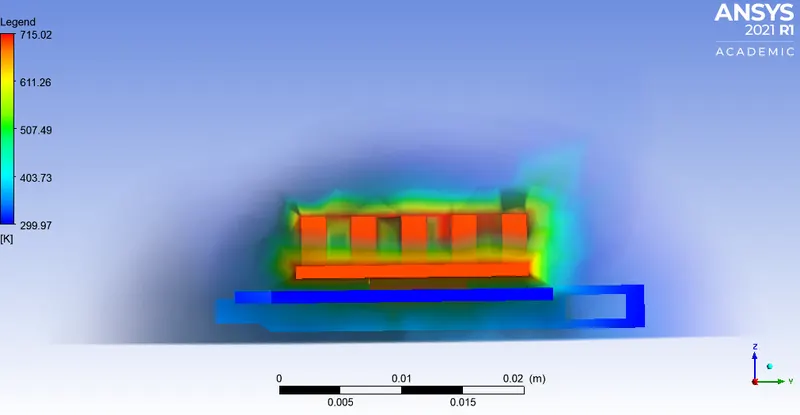
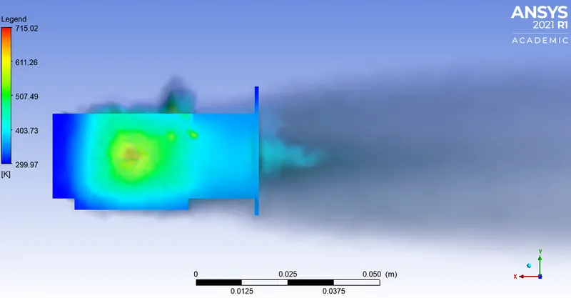
Volume Rendering: Temperature
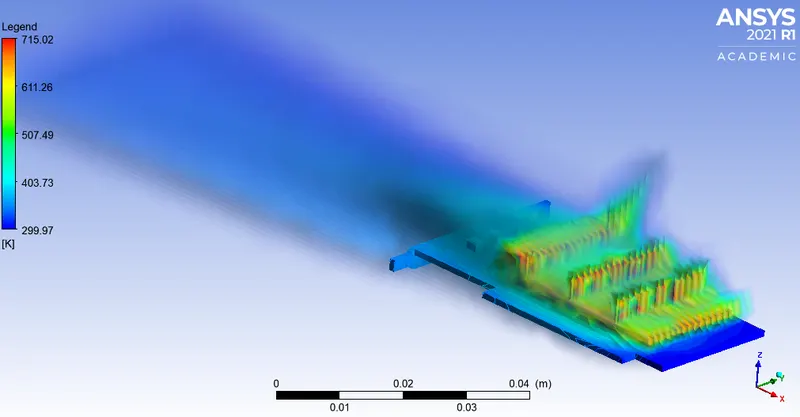
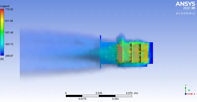
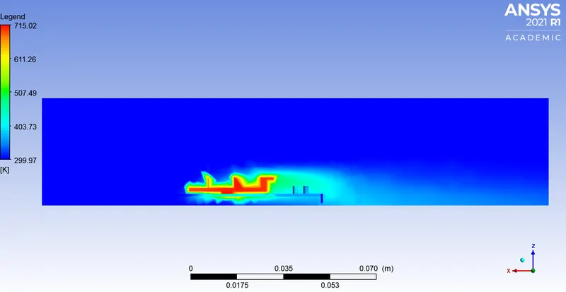
XZ plane:
Temperature distribution along XZ plane.
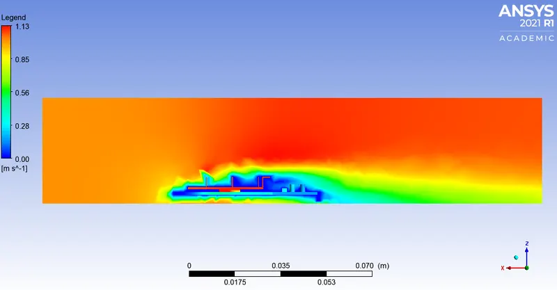
Velocity distribution along XZ plane.
Pressure distribution along XZ plane.
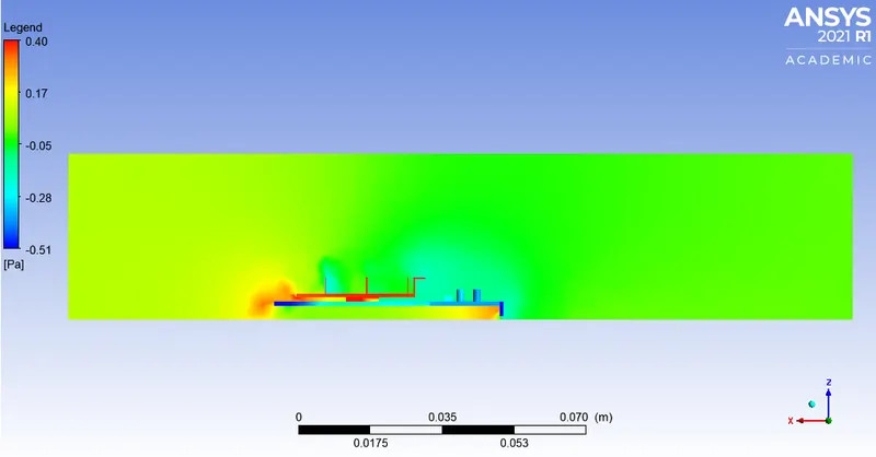
Refined case:
This mesh setup remains same for the various velocity cases.
Mesh details:
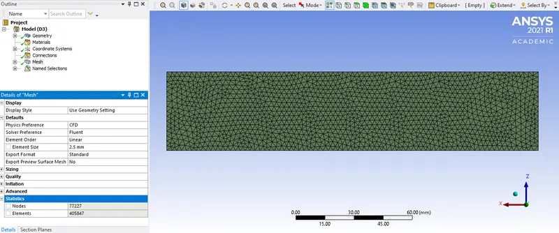
Enclosure: Mesh size = 2.5mm
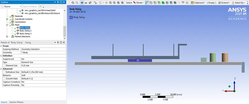
Processor: Mesh size = 0.25mm
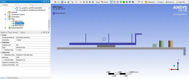
Fins: Mesh size = 1mm
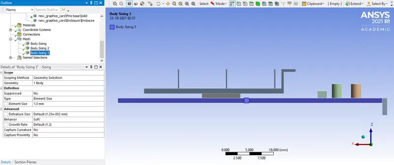
Base: Mesh size = 1mm
A) Velocity at inlet = 1m/s
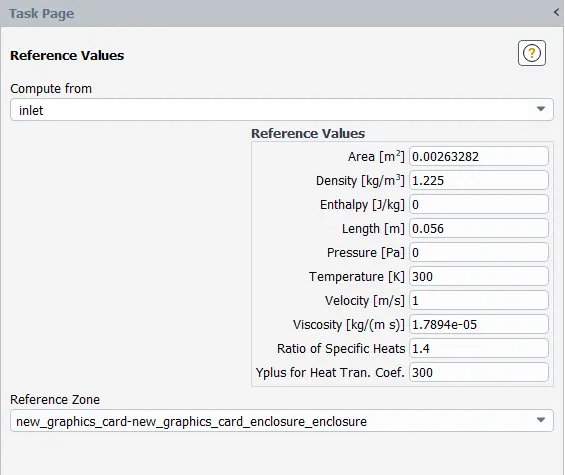
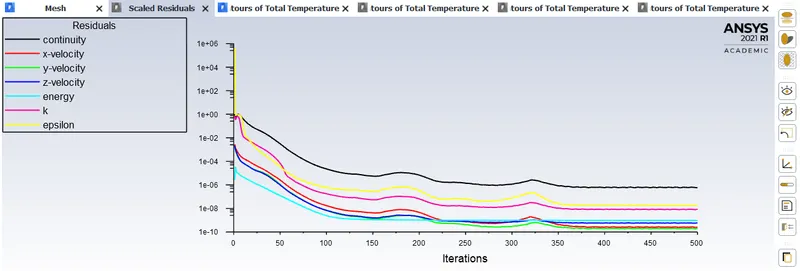
Since this is a steady state simulation there is no need to monitor the temperature contours of the model in use.
Surface integral:
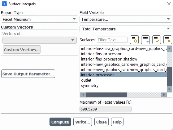
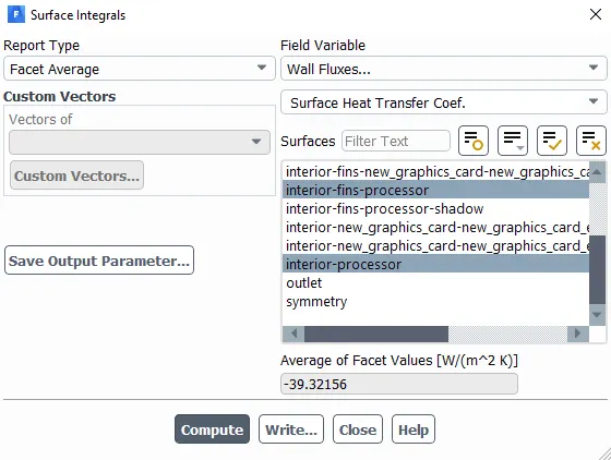
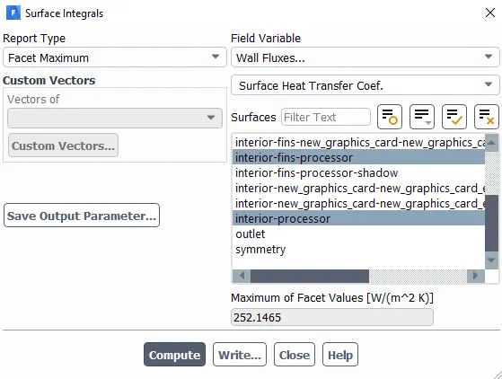
While exposrting the results be sure to select: Total temperature, Velocity, Total pressure & Surface heat transfer coeffecient.
CFD POST:
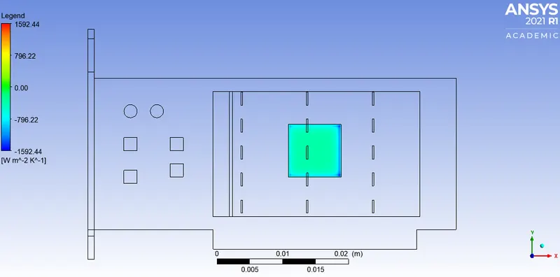
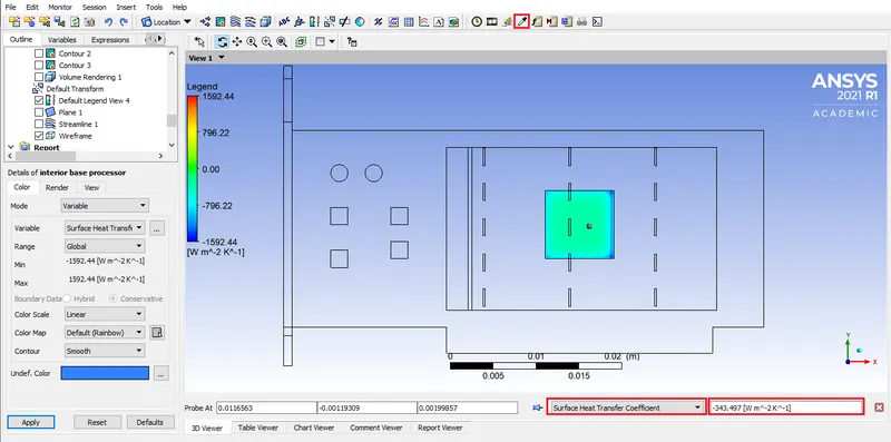
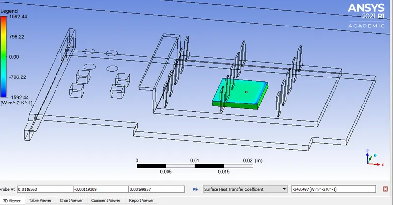
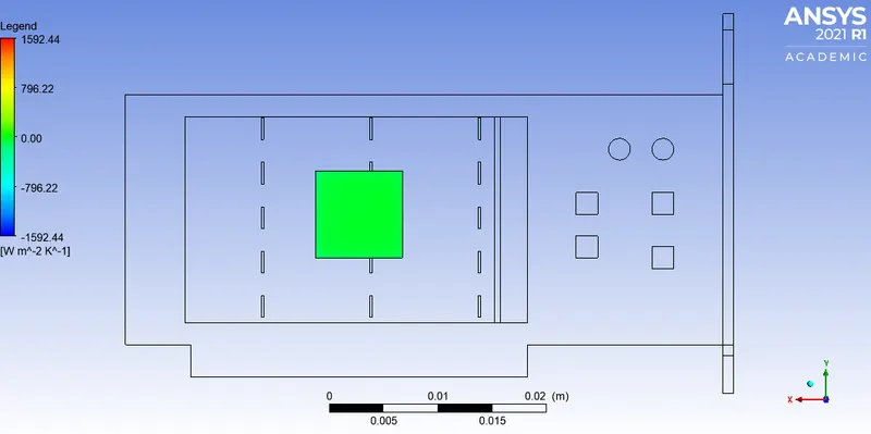
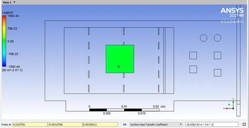
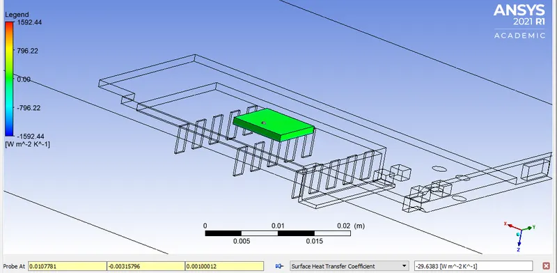
1) Surface heat transfer coeffecient
Top view:
Bottom view:
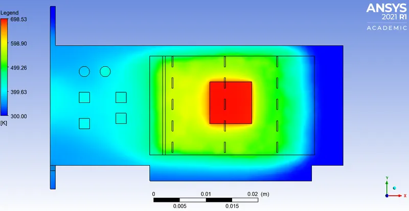
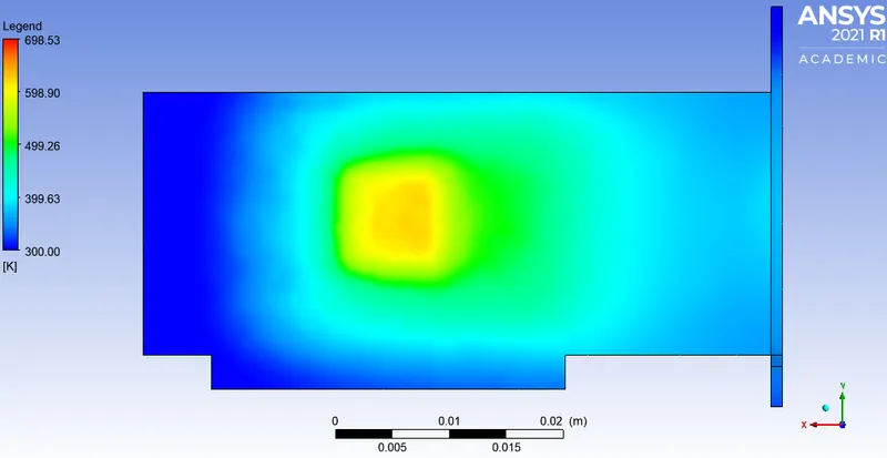
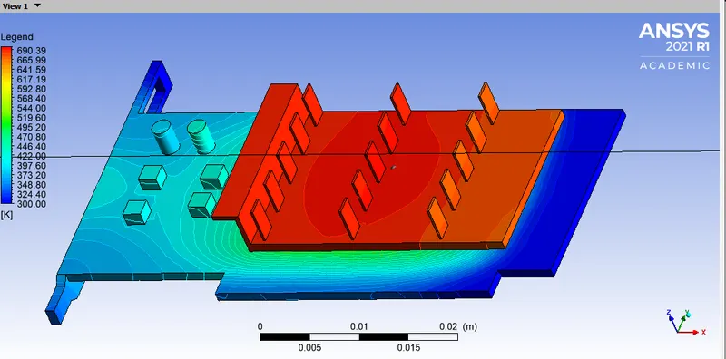
2) Temperature
Processor and base:
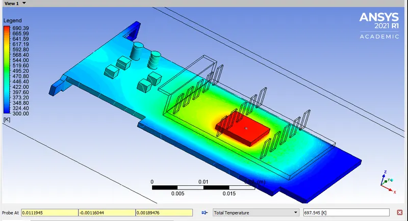
Processor, base & fins:
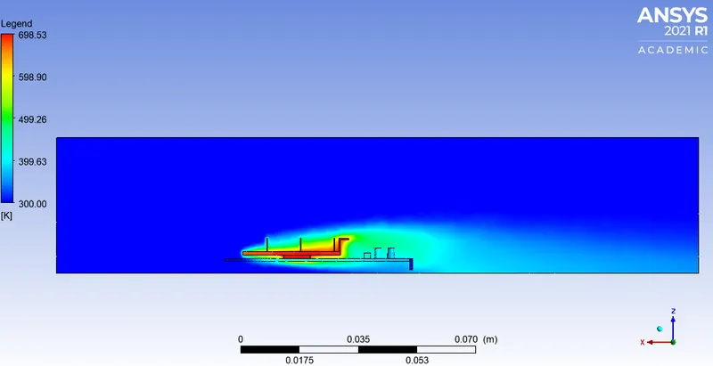
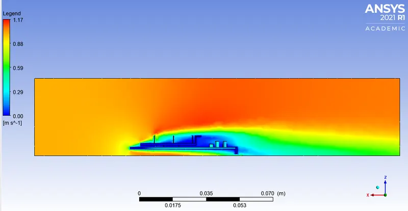
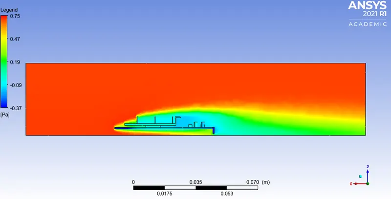
Distribution of quantities across XZ plane:
1) Temperature:
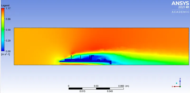
2) Velocity:
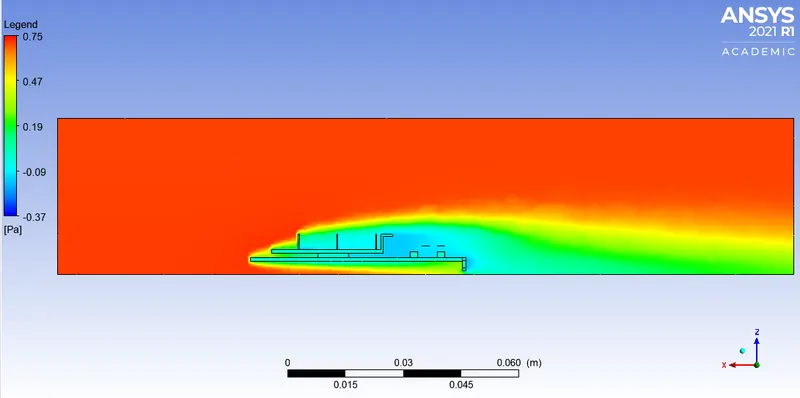
3) Pressure:
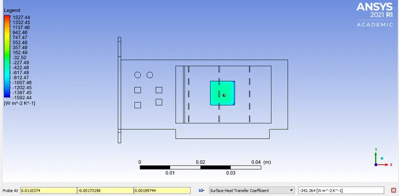
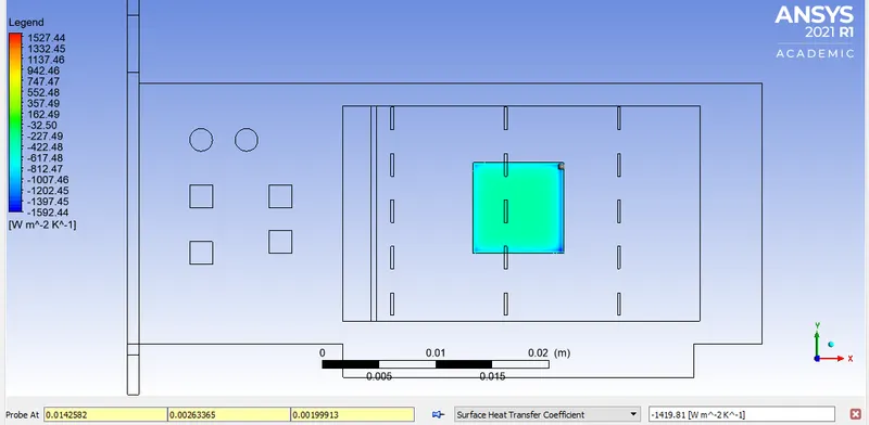
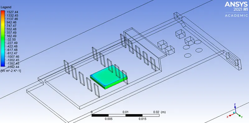
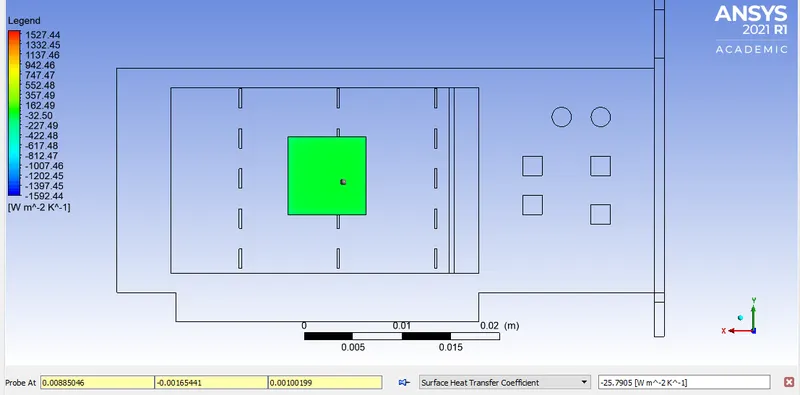
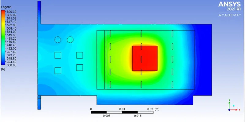
B) Velocity through inlet = 3m/s
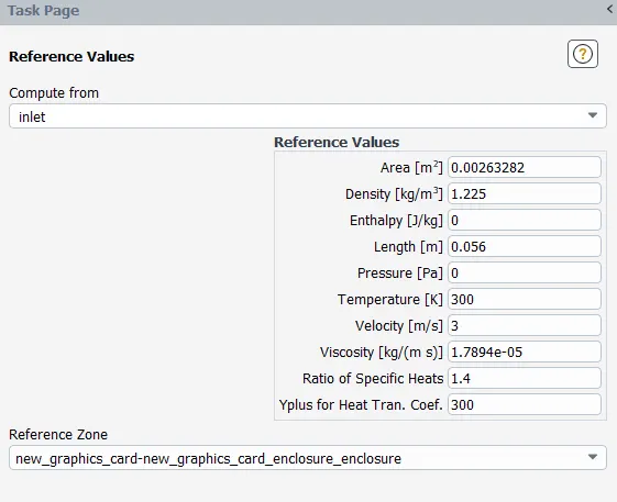
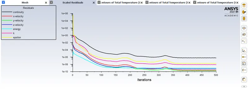
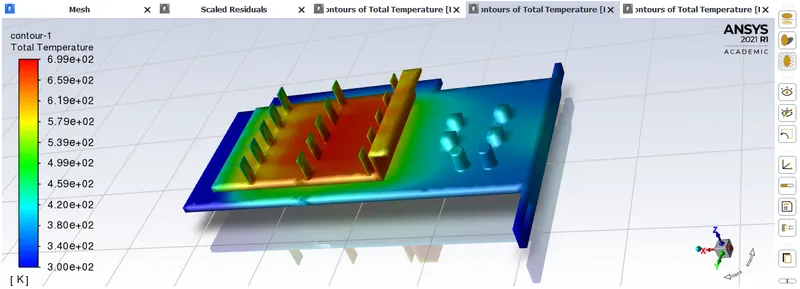
Surface integrals:
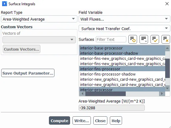
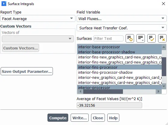
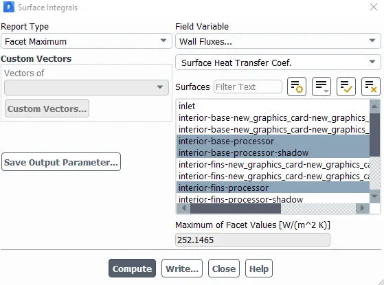
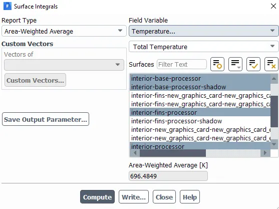
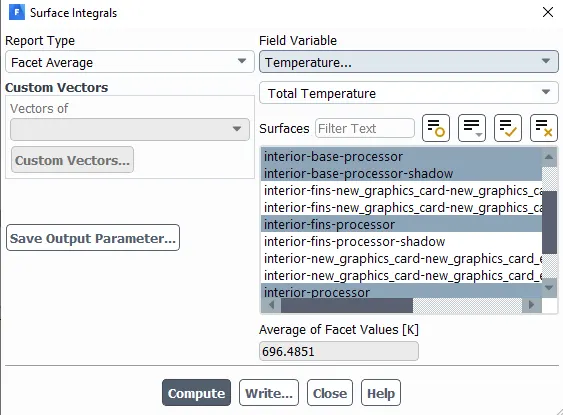
CFD POST:
1) Surface heat transfer coeffecient:
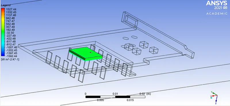
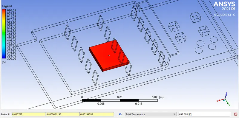
Processor and base:
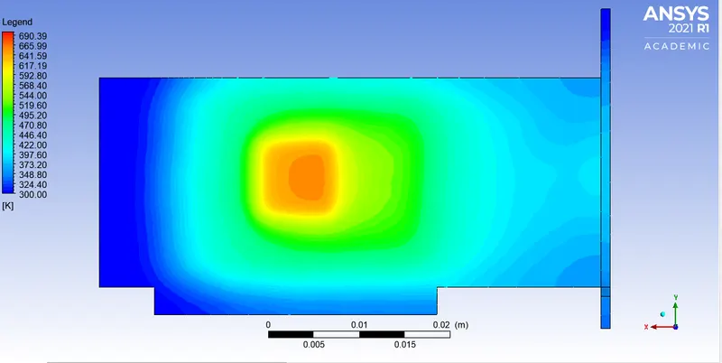
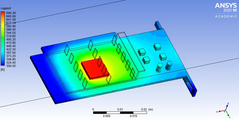
Fins, base & processor:
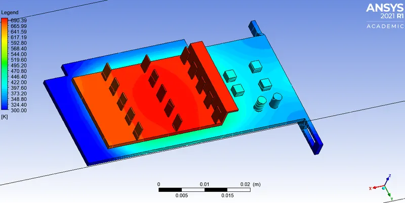
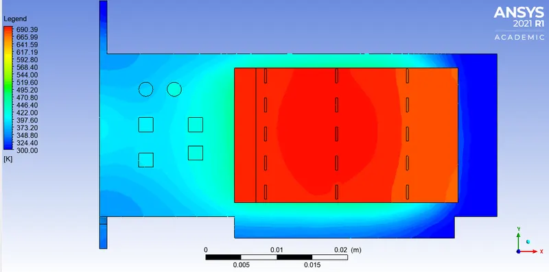
Quantities across the XZ plane:
1) Temperature:
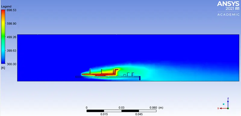
2) Velocity:
3) Pressure:
C) Velocity through inlet = 5m/s
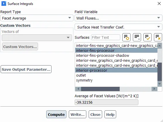
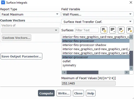
Surface intergals:
Residual:
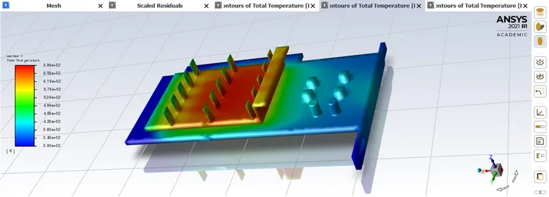
CFD POST:
1) Surface heat transfer coeffecient: Processor
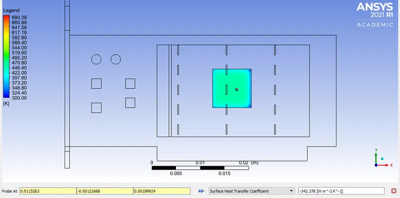
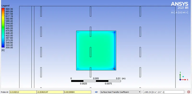
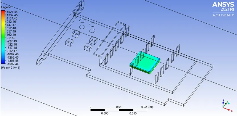
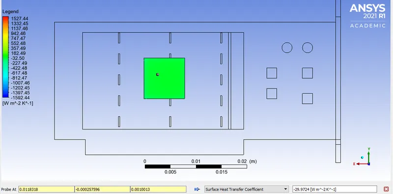
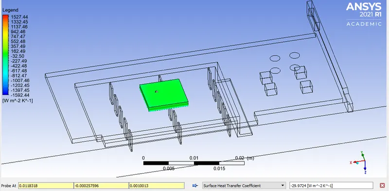
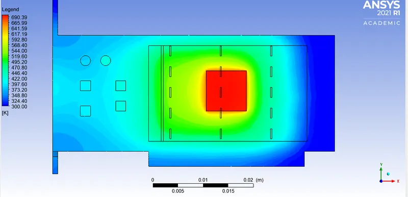
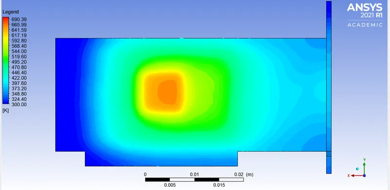
Temperature:
Processor and base:
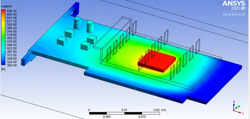
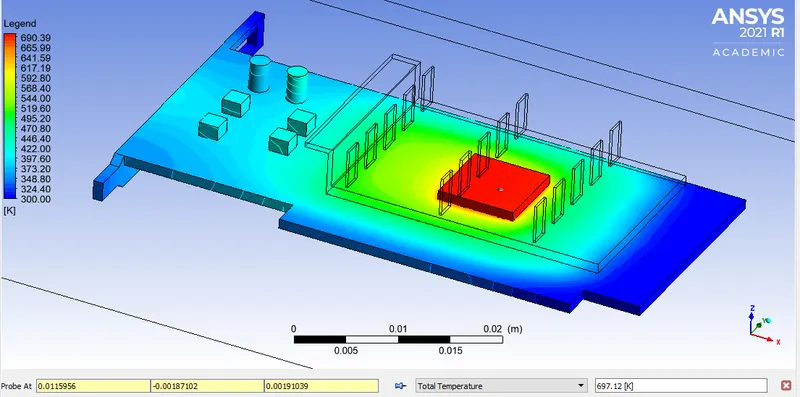
Processor, fins and base:
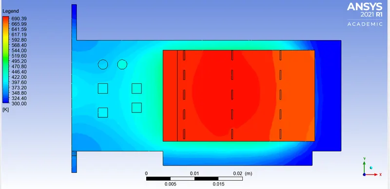
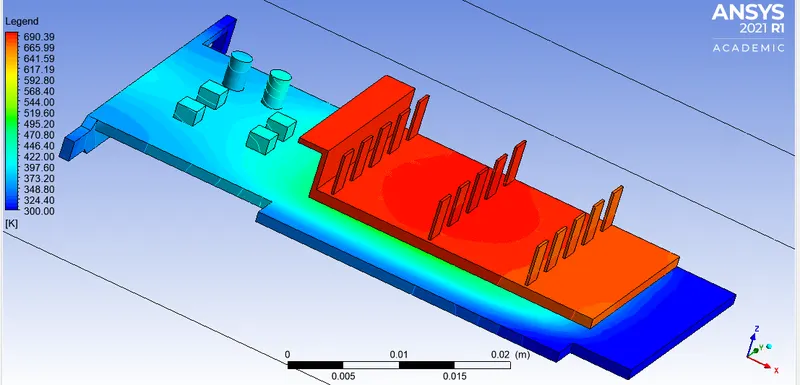
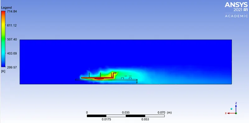
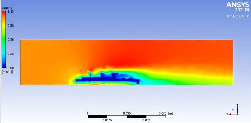
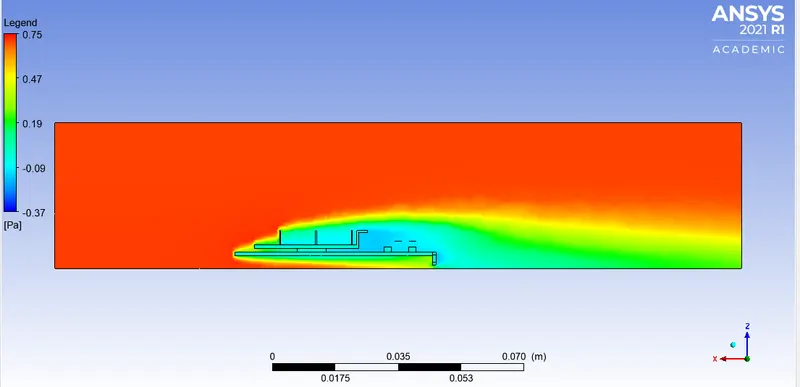
Quantities over XZ plane:
Temperature:
Velocity:
Pressure:
Conclusion:

From the above tabulated results it is safe to say that mesh refinement plays an important role in predicting correct values.
The processor being the heat generating component has been meshed finer than the rest of the components of the model because it is important to note quantities in this region.
It is clearly evident that there is almost no difference in values of average temperature with changing values of inlet velocities.
Beyond 3m/s inlet velocity there is no significant changes in the values of the observed quantities but there is a difference between the temperature values attained at 1m/s & 3m/s. So this is evidence to the effect of velocity on heat generating devices.
With improved fin design which allows proper air circulation could reduce the temperature values even further.
Using some sort of fluid medium with higher heat absorbing qualities when allowed to flow over the GPU could help in reducing temperature values generated at high loads.
Referances:
https://omnexus.specialchem.com/polymer-properties/properties/density