Week-6 Challenge: EV Drivetrain
1. Which types of power converter circuits are employed in electric and hybrid electric vehicle?
Sol: Power electronics is the process and control the flow of electrical energy by supplying voltages and currents in a form that is optimally suited for user loads.
A motor drive consistes of a power converter and the controller. the power electronic converter handles the flow of bulk power from the source to the input terminals. The controller process the command input and the feedback information to generate the signals for power converter semiconductor switches.
A Power converter is an electrical circuit that changes the electric energy from one form to the desired form optimized for the specific load. A converter may do one or more fucntions and give an output that differs from input.
A device that increases or decreases the voltage (AC or DC) of a power source depending on application. A converter that decreases voltage is called step down converter. And the converter that increase voltage is called step up converter. In EV/HEVs step up and step down converters are combined in to one unit. An application of a step down inverter is used to decrease the high voltage output from battery to the low leve voltage of 12 V OR 24 V for charging the battery or to run the auxilary loads like light, radio etc. For example, Converters will be placed in the EV as shown in the fig. below,
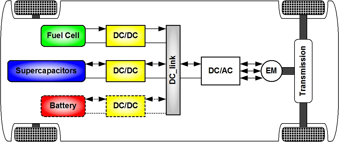
Input of Converters in EV or HEVs application is fuel cell or super capacitors or battery. In order to design highly efficient converters for the EVs power system, advanced DC/DC , AC/DC and DC/AC converters are required to adopt the output voltage and current levels with high power quality.
2. An Electric Vehicle's powertrain with 72V battery pack in shown in the diagram below. The duty ratio for acceleration operation is 'd1' and for the braking operation the duty ratio is 'd2'.
The other parameters of the electric vehicle is given below,
Motor and Controller Parameters:
Rated Armature voltage= 72 V
Rated armature current= 400 A
Ra= 0.5Ω, KΦ= 0.7 Volt second
Chopper Switching frequency= 400 Hz
The vehicle speed-torque characteristics are given by the below equation

What is EV steady state speed if duty cycle is 70%?
Sol: We know that motor torque Tm,
Tm=V(Kphi)/Ra - (Kphi)^2* Wm/Ra-----------(1)
Voltage V=Va*duty cycle
V=72*0.7 V % for 70% duty cycle
Therefore Tm=70.56-0.98Wm
AS given in question Tv=24.7+(0,0051)Wm^2---------(2)
At steady state condition , Tm=Tv;
Solving equation (1) & (2) by equating,
Wm^2+192.156Wm-45.86=0
Therefore, Wm=38.914 rad/sec =371.7991 RPM
3.Develop a mathematical model of a DC Motor for the below equation using Simulink.
ω">ω= V/Kϕ">ϕ -Ra/Kϕ">ϕ^2 .T
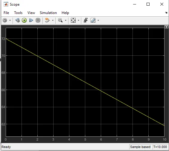
Mathematical modelling of a dc motor is hown below using simulink

The output is showing the speed torque characteristics of a DC motor as shown below,
4. Refer to the blog on below topic:
Induction Versus DC brushless motors by Wally Rippel, Tesla
Explain in brief about author’s perspective.
- In the blog of induction and dc brushless motor, the author has mentioned about the advantages and disadvantages of both induction and DC brushless motor.
-In case of DC brushless motor, permeanent magnets are used which produces a rotating magnetic fiels.This magnetic field when induces a current in the conductor. This results in froce generation in the rotor and this results in rotation of rotor.
-Whereas in case of Induction motor, the current is supplied to the stator which results in the generation of emf, when this emf comes in contact with the rotor which is generally a squirrel cage rotor type, this results in current induced in the rotor. Unlike the DC motor the rotor consistes of conductors plates and placed in a cage like structure. This also consists of bars aroud them in which current get induced and the rotor starts rotating.
-One of the main differences is that much less rotor heat is generated with the DC brush less drive. Rotor cooling is easier and peak point efficeiency is generally higher for the drive. Its mentioned that the DC brushless can drive at unit power factor, where the best power factor for the induction drive is about 85%.
-In case eof DC Brushless motor, the strength of the magnetic fiield is adjustable. when at low speeds the maximiumtorque is required magnetic field should be maximum, i.e., inverter and motor current maintened at their lowesr optimize efficiency.Where as there is no such adjustments in case of induction motor.
-As machine size grows magnetic losses increases proportionally and part load efficiency drops. In case of induction motor as machine size grows losses do not necessarily grow.
-The construction of DC brushless motor is cstly compared with an induction motor, due to the use of parmanent magnets.
However though the speed variation of induction motor depends upon the frequency input, it is difficult to control.