Week -2
- Make a Simulink model of Doorbell using solenoid block:
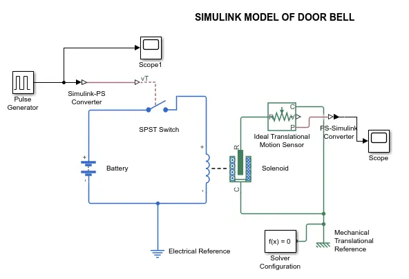
Aim: To create a simulink model of Doorbell using solenoid block using battery and observe the movement of plunger when the switch is closed.
Blocks Used:
- Battery
- Solenoid block
- Scope
- SPST Switch
- Pulse Generator
- Scope1
- Electrical Reference
- Mechanical transulation reference
- Ideal transulation motion sensor
- Solver configuration
- Simulink-PS converter
- PS-Simulink converter
Simulink Model:
Explainantion:
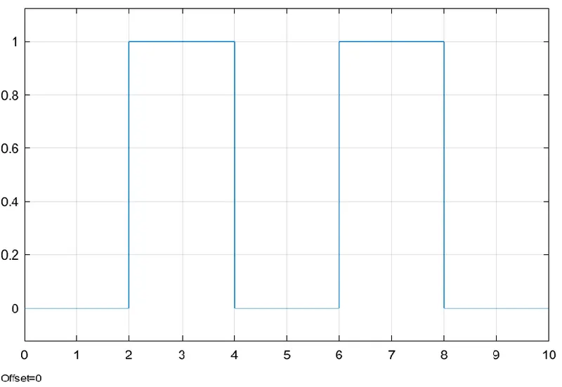
- To switch ON the Solienoid for producing bell for 2 sec and then to release, we need a step signal for 2 sec and then to be zero signal.
- Pulse generator is used to generate the pulse for 2 sec to close the SPST switch and then to open the switch. Output of pulse generator is plotted in the graph of scope1.
Scope1 output:
3. Simulink-PS converter and PS-Simulink blocks are used to connect the blocks from simulink blocks to Simscape blocks and vice versa.And electrical reference is connected to the - ve terminal of the battery. Mechanical transulation reference is connected to the port C in ideal transulation sensor and solenoid as shown in the simulink model. Solver configuration is used as variable step(default).
4. When the switch is closed battery will be connected to the solenoid coil and produces magnetic field around the coil. this will help to attract the plunger for 2 sec and when the switch is opened after 2 sec Solenoid coil will get de energize and release the plunger. When it is releasing, plunger will hit to the bell mounted near the plunger.
5. To sense the bell effect we have used a ideal transulational sensor and we can obsorve the vibration or distrubance of signal in the output shown in scope.
Scope Output:
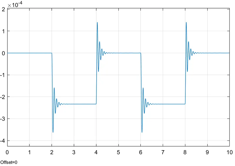
Hence, Using Solenoid we have obseved the movement of plunger in the outpu scope.
2. Use a thermistor to sense the temperature of a heater & turn on or turn off the fan as per the conditions
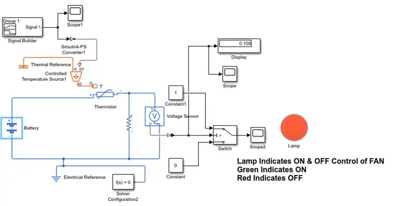
Aim : To Build a Simulink model using a thermistor to sense the temperature of a heater and turn ON and Turn OFF the Fan as per the Conditions.
Temperature source: 20 o C from 0 to 10 sec, 27 o C from 10 to 30 sec and 23 o C from 30 to 50 sec.
Fan Conditions: ON if the temperature above 25 o C, OFF otherwise.
Assumptions: Lamp used in place Fan. Lamp glows blue when Fan is in ON condition, Otherwise Red.
Blocks Used:
- Signal builder
- Simulink-PS Converter
- Scope
- Controlled temperature Source
- Thermistor
- Thermal reference
- Battery
- Resistor
- Voltage sensor
- Switch
- Constant
- PS-Simulink converter
- Display
- Lamp
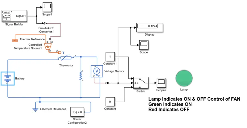
Simulink Model:
a. When the Temperature is less than 298 K or 25 o C
b. When the temperature is above 298 K or 25 o C
Input Signal to the controlled temperature Source:
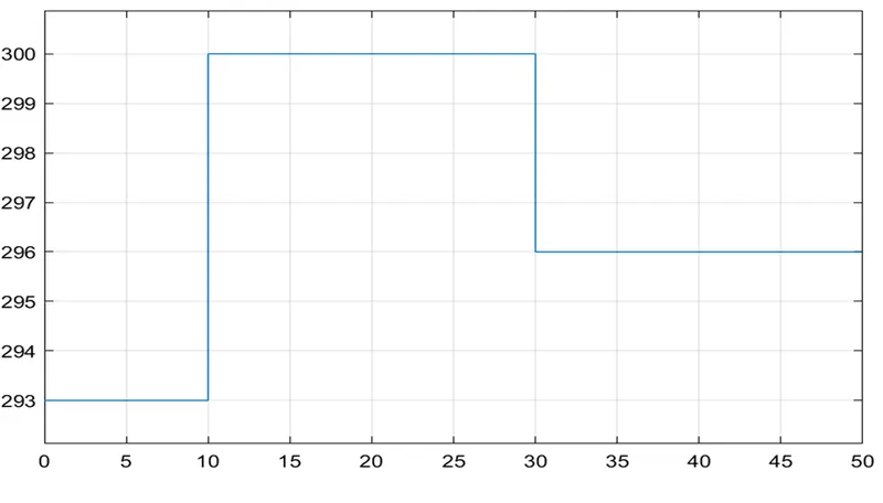
Note: Input temperature values are converted into Kelvin from oC (So 293, 300, 296 are the temperatures in kelvin.)
Signal Builder Output of Scope 1:
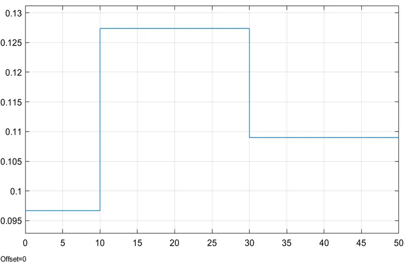
Output of Scope 2:
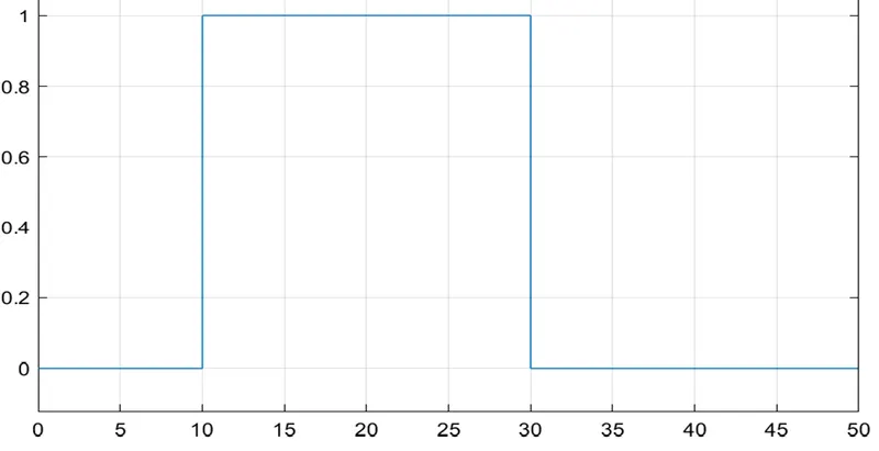 Observations from Graph:
Scope1:
- Temperature value is 293 k from 0 to 10 sec, 300 k from 10 to 30 sec and 296 k from 30 sec to 50 sec as per the given conditions
Scope:
- Output voltage across the resistor during the time slots 0 to 10 sec is 0.096, 10 to 30 sec is 0.127 and 30 to 50 sec is 0.109.
- So, it is concluded from the graph, if the voltage across the resistor is > 0.11 Fan should be ON.
Scope2:
- When the Switch is high (1) Fan will be ON (Lamp glows in Green).
- When the Switch is Low (0) Fan will be OFF (Lamp glows in red).
Explanation:
- The Input temperatures are given to controlled temperature source by using a signal builder.
- The temperature difference is set by the physical signal port S. A positive temperature difference causes the temperature at port B to be greater than the temperature at port A.so, Port A shall be connected to Thermal reference to take as absolute zero. And Port B is connected to Thermistor port A.
- A voltage source is created a used to generate heat across the resistor and a voltage sensor is connected across the resistor to know the voltage across the resistor. Electrical reference is created along with solver configuration.
- A switch is connected to Control the FAN to ON & OFF. And threshold of switch is set to > 0.11
- If the voltage across the resistor is >0.11 Fan will be ON (Lamp glows in green) and if it is less than 0.11 Fan will be OFF (Lamp glows in Red).
- Display and Scope is used to know the Output at different instants as shown in the model.
Conclusion:
- It is concluded that a thermistor is used to sense the temperature of as heater and created an output to switch on the Lamp (FAN) as per the given conditions.