Week - 4
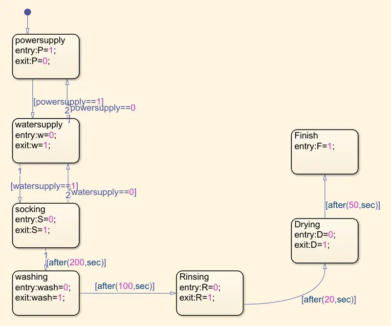
- Implement control logic of a “washing machine” using Stateflow as per given sequence:
- If the power supply is available, the system gets activated
- If the Water supply is not available, stop the process & indicate through LED
- Soaking time should be 200s followed by Washing time of 100s.
- Then rinsing happens for next 20s & dryer runs for 50s
After all the processes have completed turn on the finished LED
Aim: To Implement control logic of a washingf machine using stateflow as per the given sequence.
Blocks Used:
1. Slide switches
2. Constant blocks
3. Chart
4. Scope
5. Lamps
Stateflow Blocks:
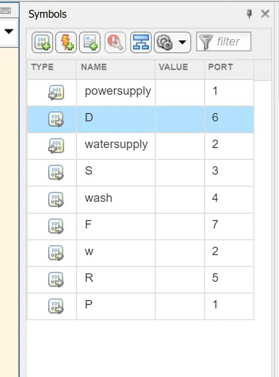
Symbol Pane (Input & output declaring to state model)
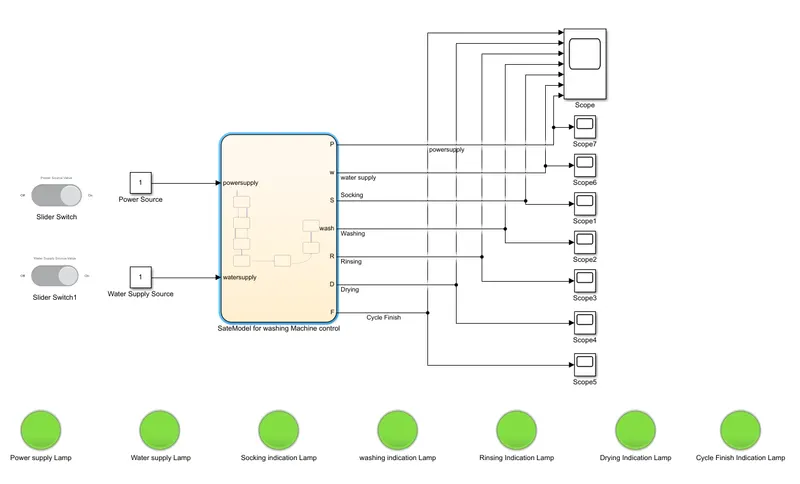
Model Using Stateflow:
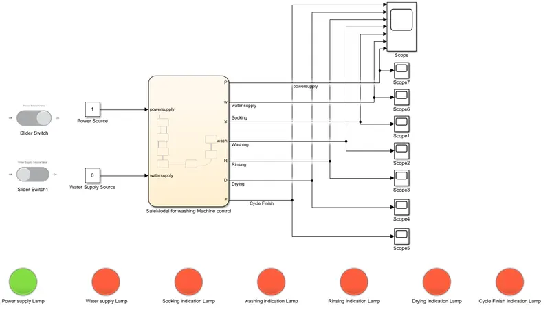
Case(i): Control logic when both power and water source present
Scope:
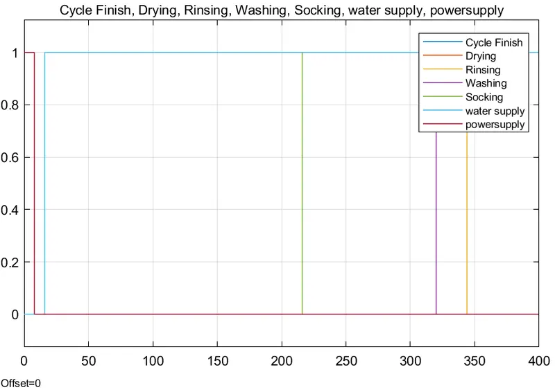
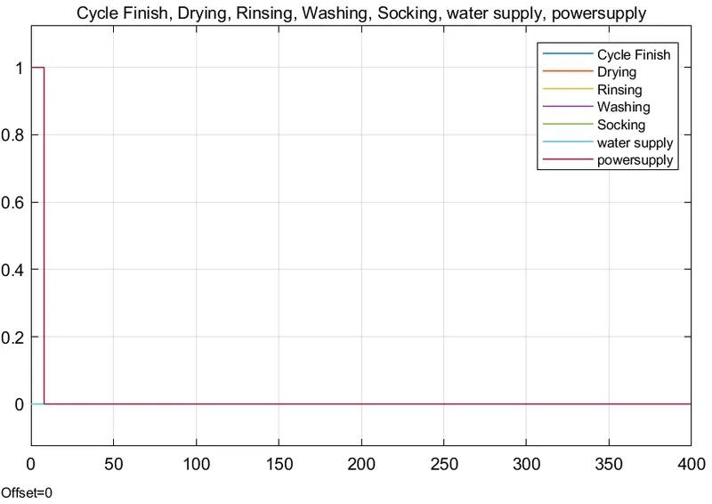
Case(ii) Control logic when water source is not available
Scope:
Explaination:
1.Water supply & PowerSupply control is created using slide switch connected with a constant block.
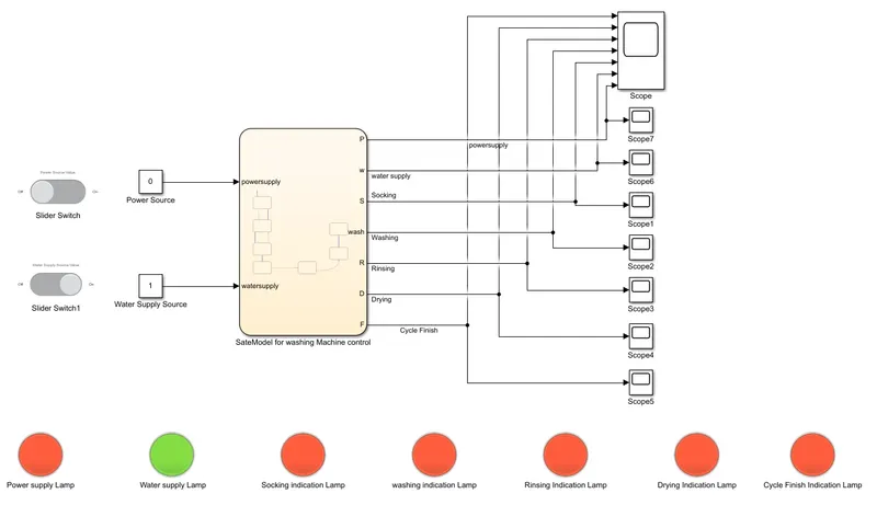
2. State flow model created for the given condictions that if the power supply is not available system will not be activated and all the lamps will glow red, as water supply is avilable water supply indicates green shown below
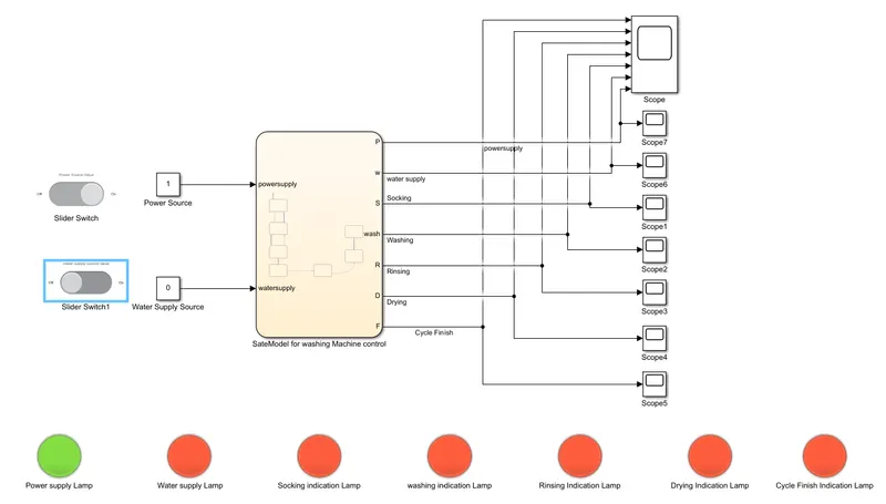
3. If the watersupply is not available the system will stop the process and the water supply lamp indicates red.
4. If both watersupply and power supply is available then if we simulate the model for 400 sec (approx) by considering the time delay for the process given in the condition, all the Lamps will indicate green and finally process finish or cycle finish lamp will glow in green. So that process is completed.
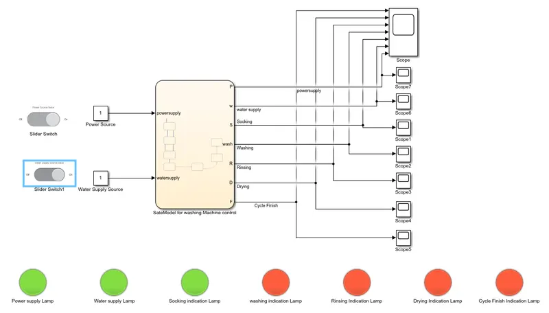
5. If we want to know the status of the process is in which state, Simulate the model for 210 sec so that we can visulise the control will be in socking state as shown below,
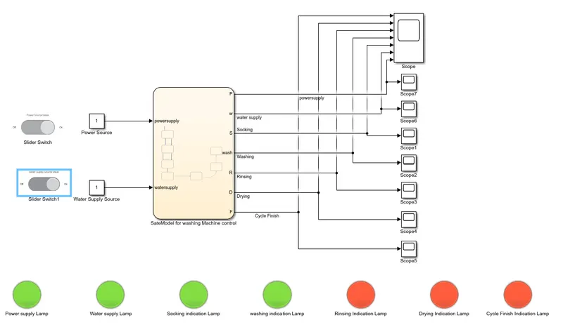
6. If we want to visualise the staus in washing mode, simulate the model for 320 sec and the washing indication lamp will glow green as shown below,
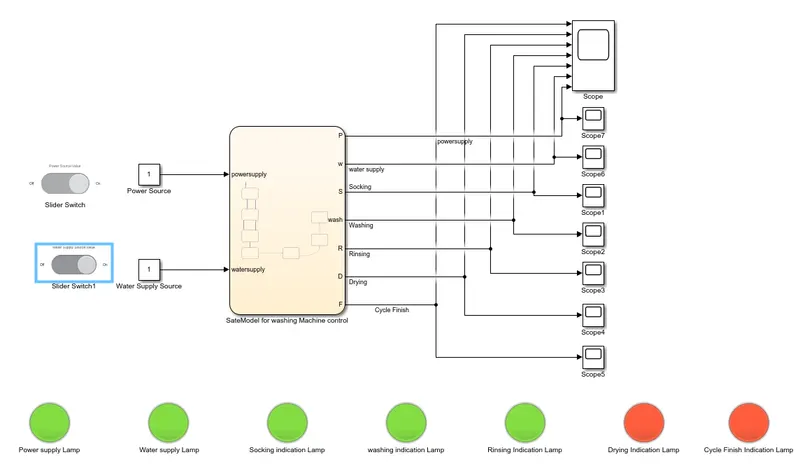
7. If we want to visualise the staus in Rinsing mode, simulate the model for 380 sec and the Rinsing indication lamp will glow green as shown below,
8. If we want to visualise the staus in Drying mode, simulate the model for 400 sec and the drying indication lamp will glow green along with cycle finished lamp as the process is completed is shown below,
So, with the given conditions, control logic for washing machine using state flow model is created.
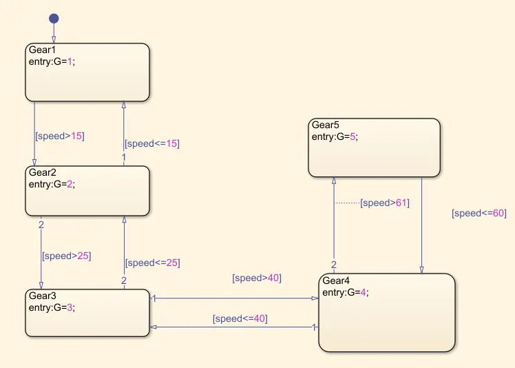
2. Make a Simulink chart for the “Gear shift” logic as per below conditions:
Speed Range(kmph) Gear
0 to 15 1
16 to 25 2
26 to 40 3
41 to 60 4
Above 61 5
Give speed input while the simulation is running & display the gear number.
Aim: To impliment the Auto gear system using state flow model as per the qiven consditions.
Blocks Used:
1. Constant
2. slider gain
3. gauge
4. Chart
5. Display
6. Scope
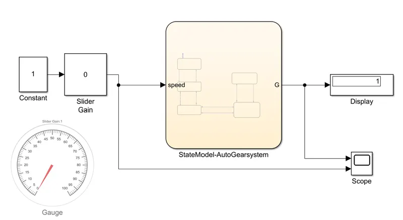
Simulink model for Auto gear system:
State flow logic:
Scope Output:
Explaination:
1. State flow logic is created by using chart block as per the given conditions to change the gear based on speed and shown in the attachment as control logic.
2. Simulink model for auto gear system is designed slider gear to vary the speed during simulation time and gauge used to know the speed variation.
3. Output gear for particular speed based on logic is displayed in the display block.
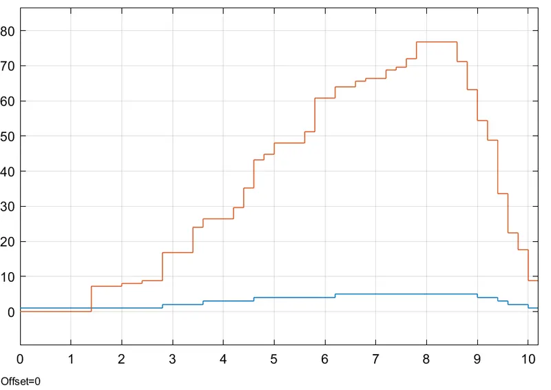
4. Scope shows the speed variation and the gear changing based on the speed variation.
5. when the speed increases the gear changes automatically from 1 to 5 gears and when the speed decreases, gear changes form 5 to 1 as shown the scope output.
6. Hence auto gear system is implemented and simulated by varying the speed during simulation of model.