Week-6 Challenge: EV Drivetrain
1. Power converter circuits used in Electric and Hybrid electric vehicles are
Bidirectional AC to DC Converter and DC to DC converter
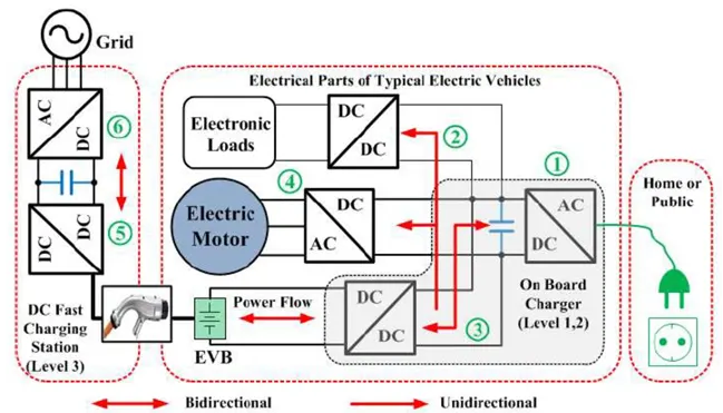
The above shows the general EV charging unit configuration.
Number 1 indicates the onboard charger level 1 and 2. AC power is converted to DC for the purpose of charging the battery through DC to DC Converter at number 3. EVB (Electric Vehicle Battery) provides power to run the Motor through dc to ac converter (number 4) and also gives power to the car infotainment system like headlight, tail light, etc through dc to dc converter(number 2). Grid power is converted to dc (number 5). dc to dc to enhance the charging power(number 6)
The onboard charger (level 1, 2) or offboard charger may be used to charge EV batteries (level 3). Hybrid vehicles are being powered with hybrid storage systems for their energy. As an onboard charger or isolated outboard charger, an EV battery charger can be built into a Car. The power flow may be unidirectional or bidirectional between the EV batteries and the grid. It is possible to control bidirectional chargers to pump the EV battery power into the grid. An EV battery can be considered an
an efficient distributed source with multiple operating modes with bidirectional functionality.
For BEV Rectifier circuit is used to charge the battery which converts AC power to DC Power
Bi-directional AC-DC converter
The filters are used alongside the rectifier circuit, It is used in the Charging module, Vehicle to Grid, and Grid to Vehicle, conditions output current and input voltage.
Lyapunov functions are used to indicate the stability or the state of equilibrium. These techniques for controlling a converter are based on either control that is voltage-oriented or flux oriented.
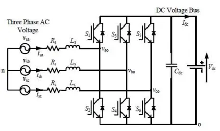
The flow of power in this converter occurs from the voltage bus of DC to the voltage end of AC. Both EVs and HEVs
use bidirectional converters that are AC-DC, as indicated above. EVS and HEVs have multiple sources of energy
namely supercapacitors with batteries. Therefore, these converters act as regulators that control the flow of
power from these multiple sources.
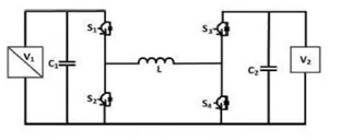
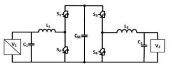
A “bidirectional DC-DC converter” is placed between the inverter and the energy source of an electric vehicle. This converter is used for conditioning various levels of voltage and a stable form of voltage from the DC bus. Further, these “Bi-directional DC-DC converters” allow operations that are based on vehicle-to-grid power transfers, therefore charging decks can use this converter. DC-DC converters can be formed in two ways, firstly with the inductor in the middle of two bridges and it is named CBB-IIM (cascaded buck-boost inductor) as shown in the below-left figure. Secondly as shown below right, there is a buck-boost capacitor that is placed in between the bridges and is of cascaded nature.
Many more converters are still there like a buck, boost, buck-boost, charge pump,
2. If the duty cycle is 70% then the EV Steady state speed
Given details
Terminal Voltage(Va)=72 Volt (Battery pack)
Armature Current (Ia)=400 amps
Armature Resistance (Ra)=0.5 ohms
`Kphi`=0.7 Volt sec
Chopper switching Frequency = 400 Hz
Duty cycle =70% i.e chopping switch is turned on for 1.75ms, turned off for 0.75ms total period is 2.5ms
Voltage for 70% of duty cycle = 72*0.7=50.4
Vehicle torque-speed equation
`Tv=24.7+(0.0051)omega^2` Equ--1
As we know the Torque equation of the motor,
`Tm=(Vkphi)/(Ra)-(kphi)^2/(Ra)*omega`
`Tm=((50.4) *(0.7))/0.5-(0.7)^2/0.5*omega`
`Tm=70.56-0.98*omega` Equ--2
Equating vehicle Torque and motor Torque equation (Equ 1 and Equ 2). By combining the Vehicle and motor torque equation we get the steady-state Speed of the EV
`24.7+(0.0051)omega^2=70.56-0.98*omega`
`(0.0051)omega^2+0.98*omega-45.86=0`
`omega= 38.911 or -231.068 (rad)/sec`
Ev steady-state speed `omega = 38.911 (rad)/sec` for 70% of the duty cycle
3. Mathematical model of a DC Motor
`omega=V/(kphi)-(Ra)/(kphi)^2*T`
Voltage, Kphi, Armature resistance, and Torque are taken as constant blocks. It can be changed by the user as per requirement.
Fetching values Voltage=72, Kphi=0.7, Ra=0.5,
subsituting the valve to this equation
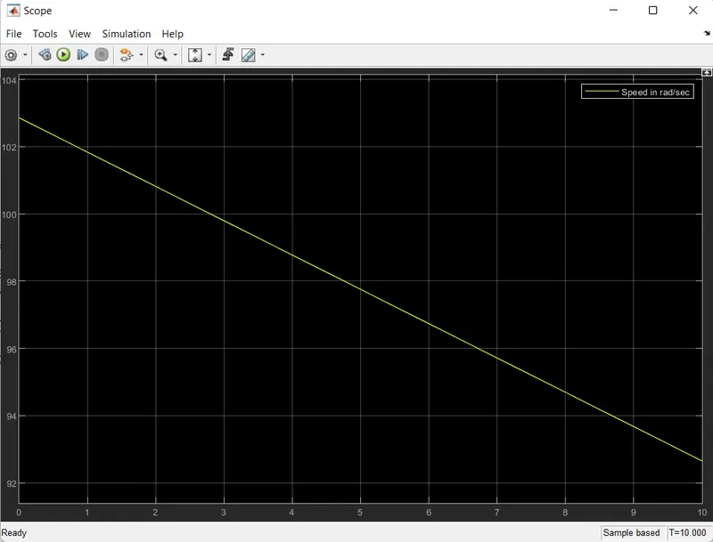
intial torque is 1
`omega=72/0.7-0.5/0.7^2*1`
`omega=102.86-1.02=101.84 (rad)/(sec)`
Final torque is 10
`omega=72/0.7-0.5/0.7^2*10`
`omega=102.86-10.20=92.65 (rad)/(sec)`
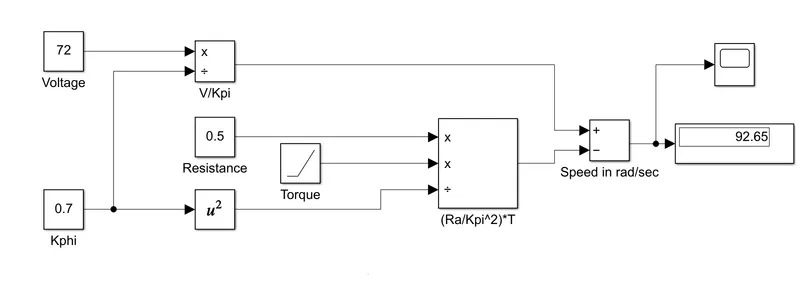
The above image shows the mathematical modeling of the DC motor for the `omega=V/(kphi)-(Ra)/(kphi)^2*T`
Graph:
4. From the author's perspective
Each engine has different requirements, such as price and performance so there is no best engine type and even in electric vehicle drives also.
Lead has been replaced by lithium and DC by either DC brushless or induction. Contactors, meanwhile, have given way to modulating inverters.
The Brushless dc machine described by the author is followed by
- In brushless dc machines, the rotor has permanent magnets that generate a DC magnetic field. The flux in this magnetic field is cut by the currents flowing stator. This causes to produce a torque interaction between the rotor and stator. As the rotor rotates, the magnitude and polarity of the stator currents must be continuously varied so that the torque remains constant and the conversion of electrical to mechanical energy is optimally efficient. The device that provides this current control is an inverter.
- Brushless DC motor produces no starting torque when directly connected to fixed frequency utility power. They need the aid of an inverter whose “phase” is maintained in step with the angular position of the rotor.
- DC brushless drives require an absolute position sensor.
- In DC brushless drive has less rotor heat generated. Rotor cooling is easier, peak point efficiency is higher, and also operates at a unity power factor. The peak point energy efficiency for a DC brushless drive will higher
- Adjusting the magnetic field strength (B) is not easy in DC brushless drive.
- In DC brushless, as machine size grows, the magnetic losses increase proportionately, and part load efficiency drops.
- Permanent magnets are expensive and Permanent magnet (PM) rotors are also difficult to handle due to very large forces that come into play when anything ferromagnetic gets close to them.
The induction motor described by the author is followed by
- The induction motor has three sets of “distributed windings” that are inserted within the stator core.
- The induction rotor has stacked steel laminations with buried peripheral conductors. Currents flowing in the stator windings produce a Rotating Magnetic Field (RMF) that enters the rotor. The voltage and currents are produced within the rotor conductors that are approximately proportionate to the voltage, hence the speed difference. Finally, these currents interact with the original magnetic field to produce forces – a component of which is the desired rotor torque.
- When a 3-phase induction motor is connected to utility type 3-phase power, torque is produced at the outset; the motor can start under load.
- Induction drives require only a speed sensor. The best power factor for the induction drive is about 85 percent. The peak point energy efficiency for an Induction drive will be lower than the DC brushless drive
-
Induction machines have no magnets and B fields are “adjustable,” since B is proportionate to V/f (voltage to frequency). This means that at light loads the inverter can reduce voltage such that magnetic losses are reduced and efficiency is maximized.
-
In induction, as machine size grows, losses do not necessarily grow. Thus, induction drives are used where high performance is desired; peak efficiency will be a little less than with DC brushless, but average efficiency much better in induction.
-
Induction motors will likely retain a cost advantage over PM machines. Also, due to the field weakening capabilities of induction machines, inverter ratings and costs appear to be lower, especially for high-performance drives.
-
Induction machines are more difficult to control. Achieving stability over the entire torque-speed range and temperature is more difficult with an induction motor. The development costs are added.
He describes the limitation of 3-phase induction motors and overcoming the limitation
Limitation of 3-phase induction motors
- It cannot operate in DC and need an AC source.
- Shaft speed is proportionate to line frequency, so the machine is at a constant speed.
- Low starting torque and running peak torque.
To Overcome the limitation Inverter is added with feedback loops
- Now possible to power an induction machine from a battery or other DC source.
- Variation of speed is achieved by adjusting the inverter frequency.
- The inverter produces the exact frequency that the motor “desires,” which gives the high torque performance compared to the previous case.
He concluded that neither DC brushless drives nor Induction drives win. DC brushless drives will dominate in the hybrid and coming plug-in hybrid markets, and induction drives will dominate in the high-performance pure electric vehicles(BEV).