Week-6 Challenge: EV Drivetrain
- Which types of power converter circuits are employed in electric and hybrid electric vehicle?
A converter is an electrical circuit which accepts a DC input and generates a DC output of a different voltage, usually achieved by high frequency switching action employing inductive and capacitive filter elements.
A power converter is an electrical circuit that changes the electric energy from one form into the desired form optimized for the specific load. A converter may do one or more functions and give an output that differs from the input. It is used to increase or decrease the magnitude of the input voltage, invert polarity, or produce several output voltages of either the same polarity with the input, different polarity, or mixed polarities such as in the computer power supply unit.
The DC to DC converters are used in a wide range of applications including computer power supplies, board level power conversion and regulation, dc motor control circuits and much more.
The converter acts as the link or the transforming stage between the power source and the power supply output.
There are various types of converter -
- AC to DC converter (Rectifier) An AC to DC converter circuit can convert AC voltage into a DC voltage. The DC output voltage can be controlled by varying the firing angle of the thyristors. The AC input voltage could be
a single phase or three phase. - AC to AC converter (frequency changer) This converters can convert from a fixed ac input voltage into variable AC output voltage. The output voltage is controlled by varying firing angle of TRIAC. These type converters are
known as AC voltage regulator. - DC to DC converter (current converter) These converters can converter a fixed DC input voltage into variable DC voltage or vice versa. The DC output voltage is controlled by varying of duty cycle.
- An Electric Vehicle's powertrain with 72V battery pack in shown in the diagram below. The duty ratio for acceleration operation is 'd1' and for the braking operation the duty ratio is 'd2'.
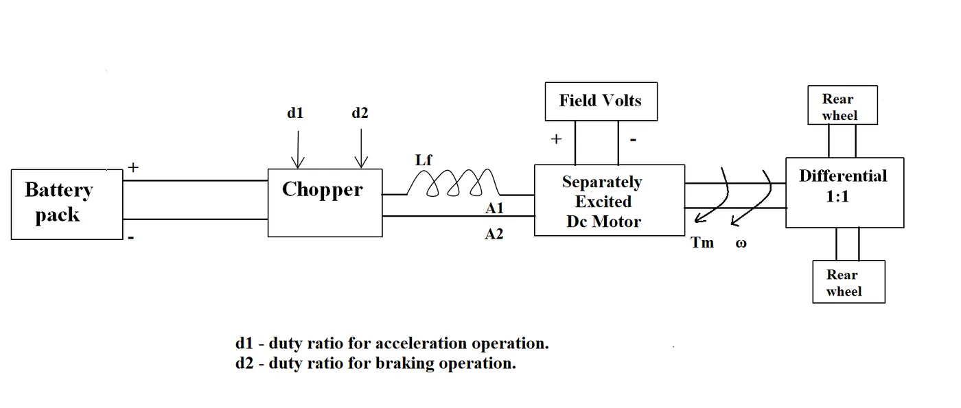
The other parameters of the electric vehicle is given below,
Motor and Controller Parameters:
Rated Armature voltage= 72 V
Rated armature current= 400 A
Ra= 0.5Ω, KΦ= 0.7 Volt second
Chopper Switching frequency= 400 Hz
The vehicle speed-torque characteristics are given by the below equation

What is EV steady state speed if duty cycle is 70%?
Solution
Given,
Armature voltage(V) = 72V
Armature Current (I) = 400A
Resistance of armature (Ra) = 0.5Ω
Motor Constant (KΦ) = 0.7 V/Sec
Duty Cycle = 70%
Chopper Switching frequency= 400 Hz
Vehicle output voltage = battery voltage*duty cycle
Vehicle output voltage = 72*0.7 = 50.4V
Torque Equation,
`Tv = Vv.(Kphi)/(Ra)-(Kphi)^2/(Ra).w`
Where,
`Tv` = Vehicle torque
`Vv` = Vehicle Voltage
`Kphi` = Motor Constant
`Ra` = Armature Resistance
`w` = Steady state speed of vehicle
Now putting all the values in the torque equation
`Tv = 50.4 * (0.7) /0.5 - (0.7)^2/0.5 * w`
`Tv = 70.56 - 0.98 w`.....(1`
`Tv = 24.7 - 0.0051 w^2`.....(2)
Now comparing both the equation
`70.56-0.98w = 24.7-0.0051w^2`
We get a quadratic equation
`0.0051w^2 + 0.98w - 45.85 = 0`.....(3)
On solveing above equation
`x = (-b +- sqrt (b^2-4ac)) / (2a)`
`x = (-0.98 +- sqrt (0.98^2-4(0.0051)-(45.85)))/ (2*(0.0051)`
On solveing this equation we get the two values
`w = 38.9 (rad)/sec) and w = -230.95 (rad)/sec`
We take the positive value, So the Steady state speed of vehicle
`w = 38.9 (rad)/sec`
-
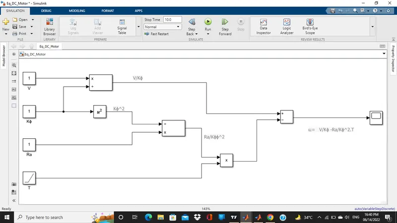
Develop a mathematical model of a DC Motor for the below equation using Simulink.
ω">ω= V/Kϕ">ϕ -Ra/Kϕ">ϕ^2 .T
Simulink Model
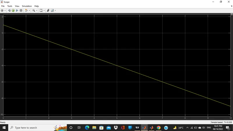
Output Plot
-
Refer to the blog on below topic: Induction Versus DC brushless motors by Wally Rippel, Tesla.Explain in brief about author’s perspective.
- Conclusion
- In this author describe dominace of IC engine in the automobile industries and discuss about the various engines. He said the all the engine are same depend upon the user chose a engine according to requirement. He also discussed about the induction motor and brushless DC motors and give his view that these two motors are very widely used in future, which we are seeing nower days in EV and many more things.
- Then author working of 3 Phase induction and brushless DC motor.
- Author also discussed about the advantages and disadvantage of both the motors
- At last author said that DC brushless drives will likely continue to dominate in the hybrid and coming plug-in hybrid markets, and that induction drives will likely maintain dominance for the high-performance pure electrics. The question is what will happen as hybrids become more electrically intensive and as their performance levels increase? The fact that so much of the hardware is common for both drives could mean that we will see induction and DC brushless live and work side by side during the coming golden era of hybrid and electric vehicles.
- References
https://www.sunpower-uk.com/glossary/what-is-a-power-converter/
https://www.tesla.com/blog/induction-versus-dc-brushless-motors