Week-6 Challenge: EV Drivetrain
Answer 1 :
Types of power converter circuits are employed in Electric and Hybrid Electric Vehicle :
The complete classification of EV converters, including topology, control, modulation and optimization, is presented in Figure bellow.
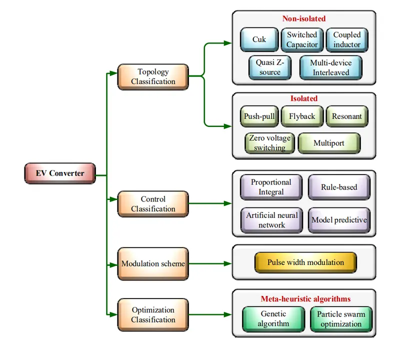
The configuration of Power converters in EVs can be categorized into two groups Non-isolated and Isolated.
The Non-Isolated converter is appropriate for EVs under medium- and high-power operation, while Isolated DC-DC converters are suitable in EVs with low- and medium-power purposes.
- Non Isolated Converters :
Non-isolated bidirectional DC-DC converters includes conventional DC-DC converters and interleaved DC-DC converters. Among them, conventional DC-DC converters are commonly employed due to their low cost, simple topology and easy control technique. The interleaved DC-DC converters have become popular due to their improved performance and efficiency.
There are 5 types of Non Isolated Converters :
a. Cuk converter :
- The Cuk converter (CC) in EVs provides flexibility to regulate the output to be lower or higher in comparison to the input voltage.
- The CC features a lower output ripple and improved efficiency since it a shares a single magnetic core.
- the CC implements an L-C filter which can regulate the peak-to-peak ripple current of the inductor more efficiently than a DC-DC buck–boost converter.
The CC topology for EV applications is designed using two inductors, two capacitors and two switches, as shown in Figure.
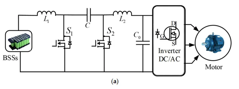
The capacitor transfers energy alternately through the commutation between switches. Besides, inductors L1 and L2 help to transform the energy from the BSS to the electric motor. Moreover, the CC can operate in both continuous and discontinuous current mode operation. The output voltage V0 across the load during the continuous mode of operation for the DC-DC CC is expressed as
Vo = Vi( −D/1 − D )
where Vi and D stand for the input voltage and duty cycle, respectively,
b. Switched Capacitor Bidirectional Converter :
- The switched-capacitor bidirectional converter (SCBC) in EVs utilizes synchronous rectification to execute the turn-on and turn-off operations.
- the SCBC has low voltage stress, a wide reaching voltage gain and needs a smaller number of components
- the SCBC suffers from a high ripple current and cannot offer high efficiency under widespread input to output voltages.
This converter is designed using three capacitors (C1, C2, C3) and one inductor (L) and four switches (S1, S2, S3 and S4), as depicted in Figure
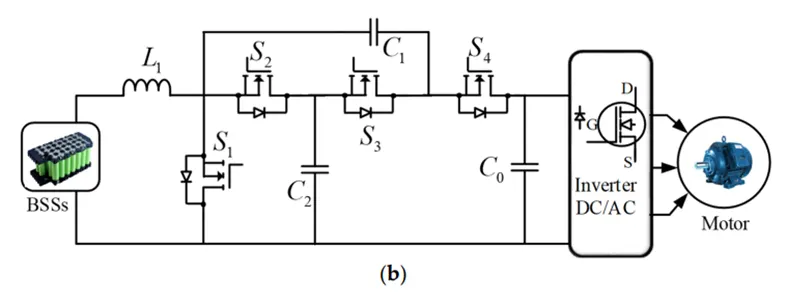
The motor takes energy from L, C2 and C0 [96]. The voltage gain of the SCBC can be written as:
Vo/Vi = 2/(1 – D)
c. Coupled Inductor Bidirectional Converter:
- A coupled inductor bidirectional converter (CIBC) in EVs provides high efficiency due to its high voltage gain and low voltage stress.
- the CIBC has secondary leakage inductance which results in low reverse recovery of the output diode.
- Due to the usage of the heavy inductor in a power boost converter, a CIBC is much preferred as compared with multiple discrete inductors as it provides less iron loss and low inductor current ripples.
- The CIBC offers other benefits including voltage transformation, changing the impedance of a circuit and galvanic isolation.
- one of the limitations of couple inductor technology is the introduction of leakage inductance, causing resonance and voltage spikes.
The configuration of the CIBC for an EV application consists of the presence of only one magnetic core which allows a smaller volume as compared with other topologies, as shown in Figure,
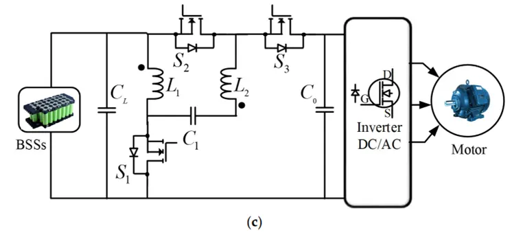
The voltage gain of the CIBC can be expressed as:
Vo/Vi = (2 + n – D)/(1 – D)
d. Quasi Z-Source Bidirectional Converter :
- The quasi-Z-source bidirectional converter (QZBC) is employed in EVs due to its advantageous features, including simple topology, common ground and wide-ranging voltage gain.
- Besides, this converter offers low voltage stress with reasonable static and dynamic performance.
- it has the drawbacks of discontinuous input current and capacitance of high voltage stress.
A switched-quasi-Z-source network is built using two inductors (L1, L2), three capacitances (C1, C2, C0) and three power switches (S1, S2 and S3), as displayed in Figure,
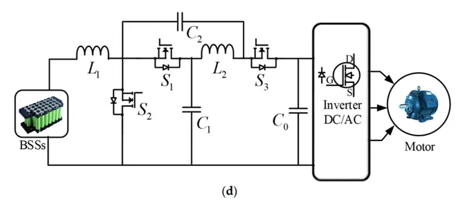
During the step-up mode, S1 is switched ON, and S2 and S3 are switched OFF. The capacitance C1 is discharged and, accordingly, power is transmitted to C2 and L2 via S1. Voltage gain can be expressed as:
MBoost = (1 + DBoost )/(1 − DBoost )
where M and D denote the voltage gain and duty cycle, respectively. During the step-down mode, S1 is switched OFF and S2, S3 are switched ON. The capacitance C1 is discharged via S2 and L1, L2 and C2 are charged via S3. Accordingly, voltage gain can be written as:
MBuck = DBuck/(2 – Dbuck)
e. Multi Device Interleaved Bidirectional Converter:
- The multi-device interleaved bidirectional converter (MDIBC) has become increasingly popular in EVs because of its advantageous features, including size, cost-effectiveness, high efficiency and lower ripples. T
- he MDIBC in EVs maintains a constant magnitude in obtaining input current and the output voltage ripples without an increase in the number of components like an inductor, capacitor and filter circuits.
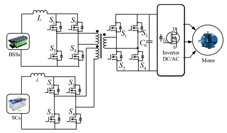
The MDIBC topology is configured using two power sources, BSSs and SCs, where BSSs act as the main power source while SCs operate as the auxiliary power source, as shown in Figure,
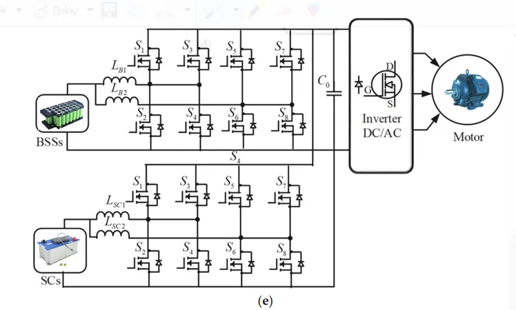
The output of the converter is controlled by various controllers such as feedback linearization, conventional dual loop and state feedback.
The expression of the duty cycle of the MDIBC is presented in the following equation:
D = 1/N (1 – Vin/Vout)
2. Isolated Converter :
The isolated bidirectional converter is designed using three primary phases, including DC/AC/DC. A high-frequency transformer (HFT) is utilized to lift the input voltage at higher values through the utilization of the intermediate AC stage. The HFT is responsible for providing galvanic isolation, leading to high voltage gain. The various isolated converters for EV applications are presented in the following sections.
There are 5 types of Isolated Power Converters :
a) Push–Pull Converter :
- The DC-DC push–pull converter (PPC) topology in EV operation is based on the transformer action which transforms the power from one side of the circuit to the other side, i.e., primary to secondary.
- The PPC has various advantages, such as simplicity and higher efficiency due to lower peak current, resulting in lower conduction losses.
- the PPC suffers from smaller filters as compared to other DC-DC converters.
- precautions are necessary while a switching operation is carried out since switches at the same time might potentially damage the converter due to the formation of a low impedance path and very high current.
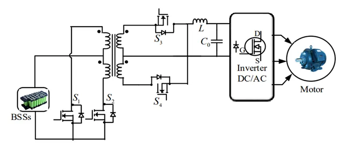
The working principle of the PPC consists of two modes, i.e., PUSH mode and PULL mode. When the converter is functioning in PUSH mode, switch S2 is ON and current flows from the battery to S2. At the same time, current in the transformer flows through switch S4 and the output capacitor. Similarly, when the converter is operating in PULL mode, switch S1 is turned on and hence current transfers from the battery to S1. The flow of current through the output capacitor in both cycles is in the same direction, hence a positive output voltage is generated. The expression for voltage gain in the DC-DC PPC is given as:
Vout/Vin = nD
b) Flyback Converter :
- The flyback converter (FC) is an isolated DC-DC converter that originates from the buck–boost converter consisting of an inductor split into the form of a transformer.
- The energy is stored in the DC-DC FC during the ON state while energy is transferred in the OFF state.
- The FC is primarily applied in low-power applications due to its cost-effectiveness, multiple isolated outputs, high output voltages and electrical isolation characteristics.
- In addition, the FC eliminates inductive filters, thus saving cost and in turn providing filtered output. Furthermore, due to the elimination of freewheeling diodes, the FC can be utilized in applications with high load voltages compared with forward converters.
- the FC possesses several disadvantages, such as high ripple current, high input capacitance and high losses.
A bidirectional DC-DC FC is configured for EVs containing two switches, two capacitors and a transformer for isolation purposes, as displayed in Figure. The working principle of the FC takes place in two modes, i.e., switch ON operation and switch OFF operation. The transformer action takes place during the switch ON operational stage,
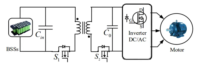
while creating a voltage across each side of the transformer. Accordingly, the magnetizing current for the closed switch operation becomes:
∆iLmclosed = VsDT/Lm
Vs = Vp N2/N1
In contrast, the magnetizing current is generated during the switch ON operational stage, thus the open switch operation becomes:
∆iLmopen = −(V0(1 − D)T/Lm) (N1/N2)
where, Vp, Vs and V0 are the primary, secondary and output voltage, respectively. T is the total time duration, Lm is the magnetizing inductance. N2/N1 is the turn ratio.
c) Resonant Converter
- A DC-DC resonant converter (RC) for EV powertrain applications consists of a combination of inductors and capacitors which is known as the resonant tank.
- The resonant tank is utilized in tuning to resonance at a given frequency.
- The magnetization inductance is used as the resonant element to execute the operation of the converter. Furthermore, the control in the RC under a no-load condition is resolved through the elimination of the magnetization current
- the RC has some limitations, such as heat problems due to magnetizing currents and complex design of the transformer,
The RC comprises four switches, four diodes and two resonant frequency components, Lr and Cr, as presented in Figure.
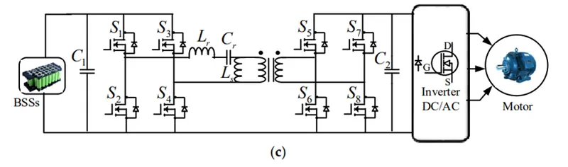
It was concluded that the proposed DC-DC RC topology achieves higher efficiency and a high conversion ratio at low cost. The quality factor (Q) and resonant frequency (Fr) for the DC-DC resonant circuit are expressed as follows:
Q = √(Lr/Cr)/Rac
Fr = 1/2π √ (LrCr)
d) Zero-Voltage Switching Converter
- The zero-voltage switching converter (ZVSC) exhibits lossless switching, cold starting and contains less circuitry in comparison with other conventional converters for EV applications.
- The ZVSC is appropriate for the EV drivetrain due to its components’ reduced size, easy control technique and significant power density. Furthermore, the ZVSC can work without additional circuitry for soft switching and provide technical benefits, including friendly control methodology and higher efficiency.
- the ZVSC needs less control and accessory power in comparison to the full-bridge component.
- the ZVSC experiences voltage stress across the switches in high-power applications.
A large capacitor is required to limit ripples at the converter output. Due to the absence of a fault tolerance mechanism, the converter is not appropriate for operation above 10 kW.
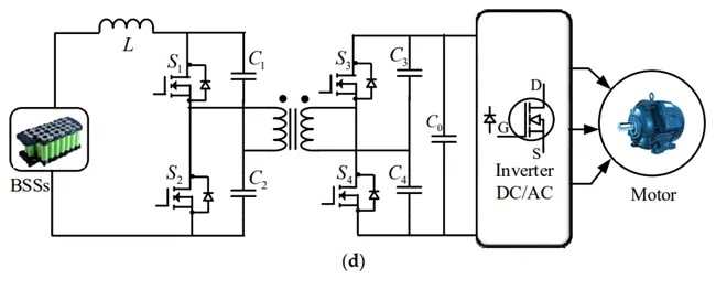
The equation of the duty cycle (D) for the ZVSC is given as:
(1 − D) × D = (n × Vout)/2Vin
e) Multi-Port Isolated Converter
- The multi-port isolated converter (MPIC) integrates the multiple input sources to extract the benefit of an individual source.
- The power recovered in the MPIC during the process of regenerative braking can be utilized to feed the power back to the input source, thus improving the efficiency as well as the functionality of the converter.
- the MPIC has some shortcomings. Due to an increase in the number of switches, synchronization becomes difficult.
- the weight of the converter also increases due to the presence of a bulky transformer.
Vgain = (n+1)/(1−D)
Answer 2 :
Given,
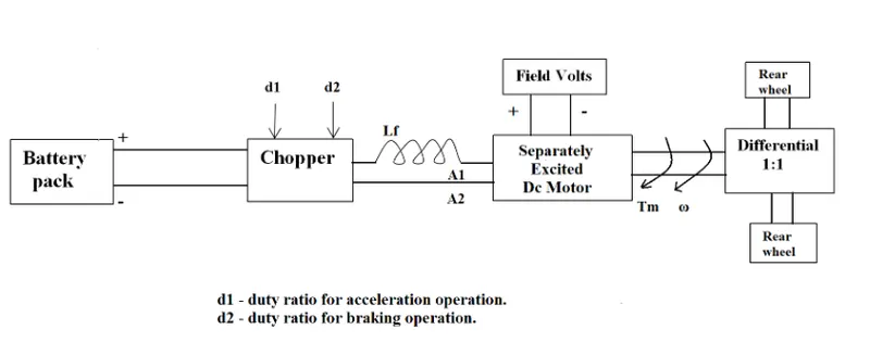
The following input parameters are given: -
Battery pack voltage (V) = 72V
Rated armature current = 400 A
Armature Resistance (R ) = 0.5Ω
Motor constant (K ) = 0.7
Chopper Switching frequency= 400 Hz
Duty Cycle = 70%
Solution: -
Vehicle Output Voltage (V ) is given by: -
V = Battery Voltage (V) * Duty Cycle
V = 72 * 0.70
Vehicle voltage = 50.4V
Now, Equation for Vehicle torque is given by: -
T`v` =(V`v` − ω. K∅ ) ⋅ K∅/Ra
Vehicle Torque (N-m)
T`v`= Vehicle voltage (Volts)
V`v`= steady state speed of vehicle (rps)
ω= Motor constant
K∅= Armature Resistance
Substituting all these values in equation, we get:
T`v` =(50.04 − 0.7 ⋅ ω) ⋅ 0.7/0.5
T`v`= 70.56 − 0.98 ⋅ ω -------------- 2
We were given
T`v`= 24.7 + 0.0051 ⋅ ω^2 ------------ 1
On solving 1 & 2 equations
70.56 − 0.98 ⋅ ω = 24.7 + 0.0051 ⋅ ω^2
We get
0.0051 ⋅ ω^2 + 0.98 ⋅ ω − 46.94 = 0
Since quadratic equation, we get two values as
ω = 38.85 rad/s and ω = -230.95 rad/s
We take the positive value,
Steady state speed of vehicle = 38.85 rad/s
Answer 3 :
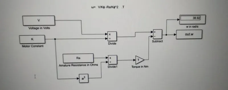
Developing a mathematical model of a DC Motor for the below equation using Simulink.
ω= (V/Kϕ)-(Ra/Kϕ^2) .T
Matlab Scripth for Mathe matical model :
clear all
close all
clc
% Torque Speed Characteristics of DC Machine.
% Array of motor speed in rad/sec
Speed = linspace(0,500,50);
% Input of Speed constant of a motor (rpm/v)
N_s = input('Enter the value of Speed Constant of Motor = ');
% Input the Battery voltage supply value.(volts)
V = input('Enter the value of Voltage Supply = ');
%Input the Armature Resistance. (ohms)
R_a = input('Enter the value of Armature Resistance = ');
% Back E.M.F developed
EMF = 1 ; % back emf is directly proportional to speed constant given in the dat is per unit voltage
%Calculating the constant of proportionality in emf and speed relation
k_phi = (EMF*60)/(N_s*2*3.14);
% the DC motor Speed torque charateristics
% T = ((V*k_phi/R_a) - ((k_phi)^2/R_a)*omega)
% Calculation of Torque
 T = ((V*k_phi/R_a) - (((k_phi)^2/R_a).*Speed));
 % To calculate Total Current in Ampere
 TC = (V - EMF)/R_a;
 % To Calculate the maximum Torque
 T_max = k_phi*TC ;
 %Convert Speed value in rpm from rad/sec
 Speed = Speed*60/(2*3.14);
 % Plotting the D.C.Machine charateristics w.r.t Speed Vs Torque
 plot(Speed,T,'color','r','linewidth',3);
 xlabel('Speed (RPM)');
 ylabel('Torque (Nm)');
 title('D.C.Machine Charateristics wrt Speed Vs Torque');
Simulink Model :
Results :
Explanation :
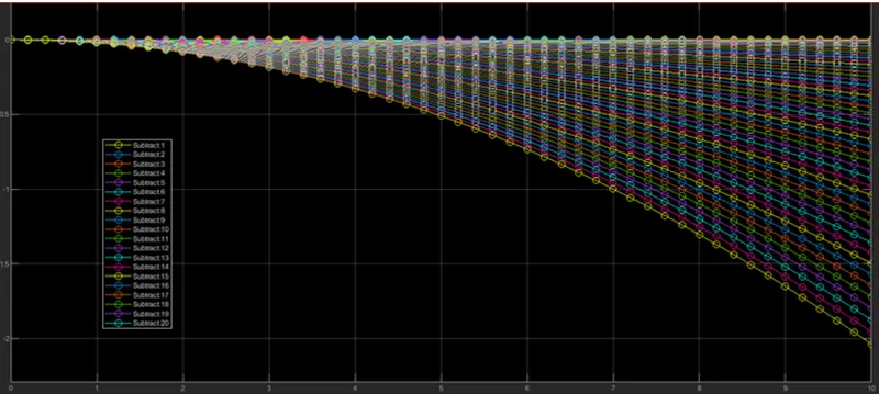
1. The speed is determined with a help of mathematical model in simulink, By preparing the model which governs the above Speed formula.
2. New model in Simulink is opened and saved with name DC_Mmotor_sSpeed,then in that model we take constant block it’s input is “V“ from the workspace.
3. “K” is Eb/speed so we take “Eb” in constant block and it’s input as ”EMF” from the workspace.
4. Further we take divide block and connect multiplication port to EB as it is directly proportional and divide port to Speed from workspace, and create a Subset of it with asking for output port block.
5. In Similar way Subset is created for Ra/K^2*T as shown in Model diagram.
Answer 4 :
The Author have explained the similarities and differences of DC Brushless motor and Induction Motor.
DC Brushless motor :
- Rotor includes to a more permanent magnets the generate DC magnetic field which enters stator core and interacts with current flowing with in the windings to produce torque interaction between rotor and stator.
- The device that provides the current control is called an inverter without this brushless motors or useless.
- Brushless DC motor producers no starting torque when directly connected to fix frequency utility power
- Need the aid of an inverter whose phase is maintained in step with the angular position of the rotor
- Heat is generated with DC brushless drive and it is easier to cool and also have peak point efficiency in generally higher for this drive.
Induction motor
- forerunner of three phase induction motor was invented by Nicola Tesla.
- three phase induction motor and DC brushless motor are virtually identical both have three set of distributed windings that are inserted with a stator
- It has ability to start under load
- No inverter is needed
- The best power factor for induction drive is about 85%
- Induction machines have no magnets and be feel adjustable since be is proportionate to be by f which mean that light loads that inverter can reduce voltage such that magnetic losses are reduce and efficiency is maximized
Permanent magnets are very expensive and also create various forces which are difficult to handle during the action. Hence induction motor have an extra aids with no permanent magnets and are more reliable in many cases
On speaking about the technicalities induction motors have control loss which are complex and difficult to understand and intern it is difficult to control. Achieving stability for the entire to speed range and over temperature is more difficult with induction motor when compared with DC brushless motors
Thurs the comparison between DC brushless motors and induction motors is always a tie game when considered various factors and various demand of the vehicle and the consumer when taken into account.