Week-6 Challenge: EV Drivetrain
#1. Power converter circuits are employed in electric and hybrid electric vehicle
Power Converters
A power converter is an electrical circuit that changes the electric energy from one form into the desired form optimized for a specified load. In electric and hybrid vehicles the power electronic converters are used to handle the power from source to the powertrain (motor input terminal). To control the output voltage and current levels efficient types of convertes are used in electric vehicles.
There are 3 types of power converter mainly used in EV and HEV
AC - DC Converter
This type of converter take an AC power supply and convert to DC power. In EV and HEV the vehicles get propulsion power from an external source like a charging station. The charging stations are AC and battery need DC. So an AC - DC converter is used. This type of convertes are used in Plug in EV and HEV's.
DC - DC Converter
Mostly this type of converter are used to step up or step down voltage level as required for the vehicle. The main purpose of using DC-DC converters is to control voltages on various devices as per their requirements. There are 2 types of DC - DC converters:- Isolated and Non Isolated type.
Isolated Type Power Converters
- Half Bridge Converter
- Full Bridge Converter
- Push Pull Converter
Non-Isolated Type Power Converters
- Buck
- Boost
- Buck-Boost
- CUK
- Charge Pump
DC - AC Converter
The converter is used to convert DC power to AC power inorder to power AC electrical appliemces in car. The battery's DC power is converter to AC using DC - AC power converters.
#2. What is EV steady state speed if duty cycle is 70%?
The given parameters are:-
Rated Armature voltage= 72 V
Rated armature current= 400 A
Ra= 0.5Ω, KΦ= 0.7 Volt second
Chopper Switching frequency= 400 Hz
Ans:
The vehicle speed-torque characteristics equation:-
 -----------------------> (1)
Duty Cycle = 70% = 0.7
Average Voltage = 0.7 x 72 =50.4V
Torque Equation of Motor is :-
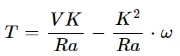 ---------------------------------> (2)
T = (50.4 x 0.7 / 0.5) - (0.7^2 /0.5) x ω
T = 70.56 - 0.98.ω
By comparing the 2 Torque equations
24.7 + 0.0051.ω^2 = 70.56 - 0.98.ω
(0.0051.ω^2) + (0.98.ω) - 45.86 = 0 ------------------> (3)
Since we get a quaduatic equation ax^2 + bx + c =0, solve equation (3) using the formula:-
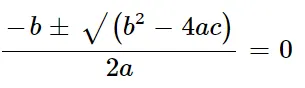
By sustituting the values we get two values as,
ω = 38.915 rad/sec & ω = 231.072 rad/sec
Steady state speed if duty cycle is 70% = 38.915 rad/sec or 371 RPM
#3. Develop a mathematical model of a DC Motor for the below equation using Simulink.
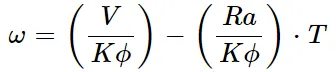
Lets Assume the values,
V = 50V
Kϕ = 0.7
Ra = 0.5
The Mathematic Model of a DC motor has been disgned as per assumed values:
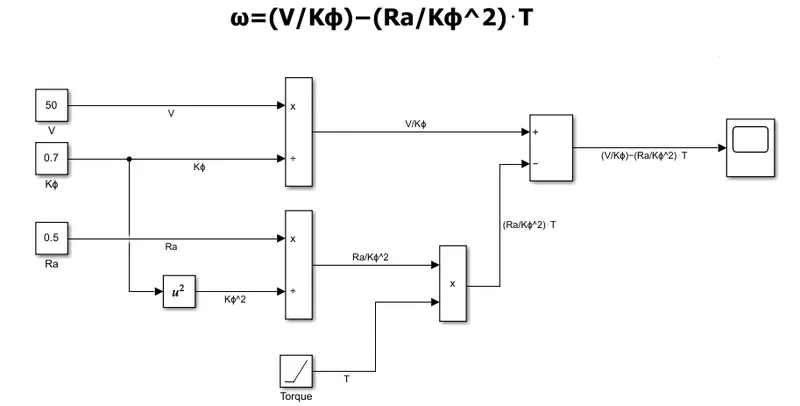
Result
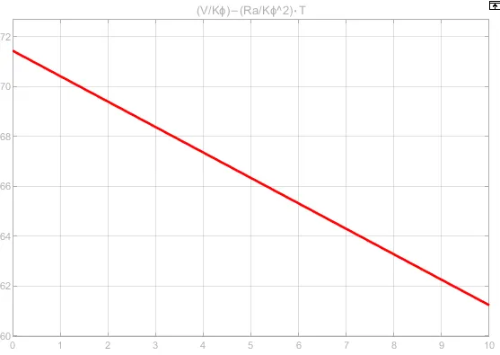
The output for the equation , ω=(V/Kϕ)−(Ra/Kϕ^2)⋅T
#4. Induction Versus DC Brushless Motors
In the blog the author Wally Rippel discribes the dominance of internal combustion engine in the vehicle industry. The author explains the latest EV technologies related to Brushless DC motor and Induction Motors that are used in electric vehicle nowadays.
Brushless DC Motor (BLDC)
Wally explains about the sic working principla of a BLDC motor that, the rotor includes two or more permanent magnets that generate a DC magnetic field. This magnetic field enters the stator core and interacts with currents flowing within the windings to produce a torque interaction between the rotor and stator. As a result the rotor ratates. By this process the electrical Energy is converted to mechanical energy. The device that provides this current control is called an inverter. Without it, brushless motors are useless motors.
Induction Motor
The 3-phase induction motor was invented by Nikola Tesla. He said the stator of both the motors are virtually identical. Both motors have three sets of windings that are inserted within the stator core. The two motos have different types of rotors. Then he explains about the working principle of the induction motor that the three phase supply is given to the stator winding, a rotating magnetic field of constant magnetic field is produced. The frequency of this magnetic field by the rotor is equal to the difference between the applied electrical frequency and the rotational frequency of the rotor. So that an induced voltage exists across the shorted structure that is proportionate to this speed difference between the rotor and electrical frequency. As a result a currents is produced within the rotor conductors that are approximately proportionate to the voltage. This currents interact with the original magnetic field to produce forces – a component of which is the desired rotor torque.
He also quoted a comparison between BLDC motor and Induction Motor
| Brushless DC Motor | Induction Motor |
|
|
He concluded that their is no winner, both the BLDC and Induction motors are best as per their features and requirements.