Week-6 Challenge: EV Drivetrain
AIM:
1. To explain the types of power converter circuits employed in an electric and hybrid electric vehicle.
2. To calculate the EV steady-state speed of the DC motor.
3. To develop a mathematical model of a DC Motor for the given equation.
4. To study and explain the concept of Induction Versus DC brushless motors by Wally Rippel, Tesla\
1. Types of power converter circuits employed in an electric and hybrid electric vehicle.
Ac/Dc Converter (Rectifier) (On-Board Chargers):
On-Board Chargers (OBC) are used to convert 120V or 240V AC from a wall socket or wall charger into a DC voltage for charging an EV/HEV battery. In addition, the OBC performs other functions including charge rate monitoring and protection The OBC system takes the AC input source, converts it to high voltage DC through the rectifier, and provides Power Factor Correction (PFC). The resulting DC signal is chopped into a switched square wave to drive a transformer to create the required output DC voltage. The output voltage is filtered to the final DC voltage using sync FETs under the control of additional isolated gate drivers. The entire system can be monitored and controlled via an Isolated CAN bus
DC/DC Converter (Chopper) (Auxiliary Power Module)
DC-DC converters are used to convert dc voltages from one voltage domain to another for powering various auxiliary systems of an Ev/HEV. This high voltage to low voltage (HVLV) dc-dc converter is often referred to as an auxiliary dc-dc, or Auxiliary Power Module (APM). The main dc-dc converter changes dc power from an on-board 200-800V (HV) battery into lower dc voltages, like 48V or 12v, to power headlights, interior lights, wiper and window motors, fans, pumps, and many other systems. The converter may be unidirectional, supplying energy only from the high-voltage domain to the low-voltage domain, or it may be bidirectional. While a unidirectional dc-dc can use diodes instead of switches on the LV side, a bidirectional module requires switches.
Dc/AC Converter (Inverter)
Traction inverters are used to convert stored dc high voltage from a battery or dc bus link into multi-phase ac power for driving a traction motor of an EV/HEV. The traction inverter is typically capable of transferring power in the 20 to 100 kW range, with switching voltages in the 200 to 800V range, and currents in the hundreds of amperes. The traction inverter converts dc power from an onboard high voltage (HV) battery into ac power to drive the main motor or motors of an electric vehicle. In addition, traction inverters perform functions such as voltage boosting, switch protection, and regenerative braking support. The entire system can be monitored and controlled via an automotive bus such as CAN.
2. An Electric Vehicle's powertrain with a 72V battery pack is shown in the diagram below. The duty ratio for acceleration operation is 'd1' and for the braking operation the duty ratio is 'd2'.
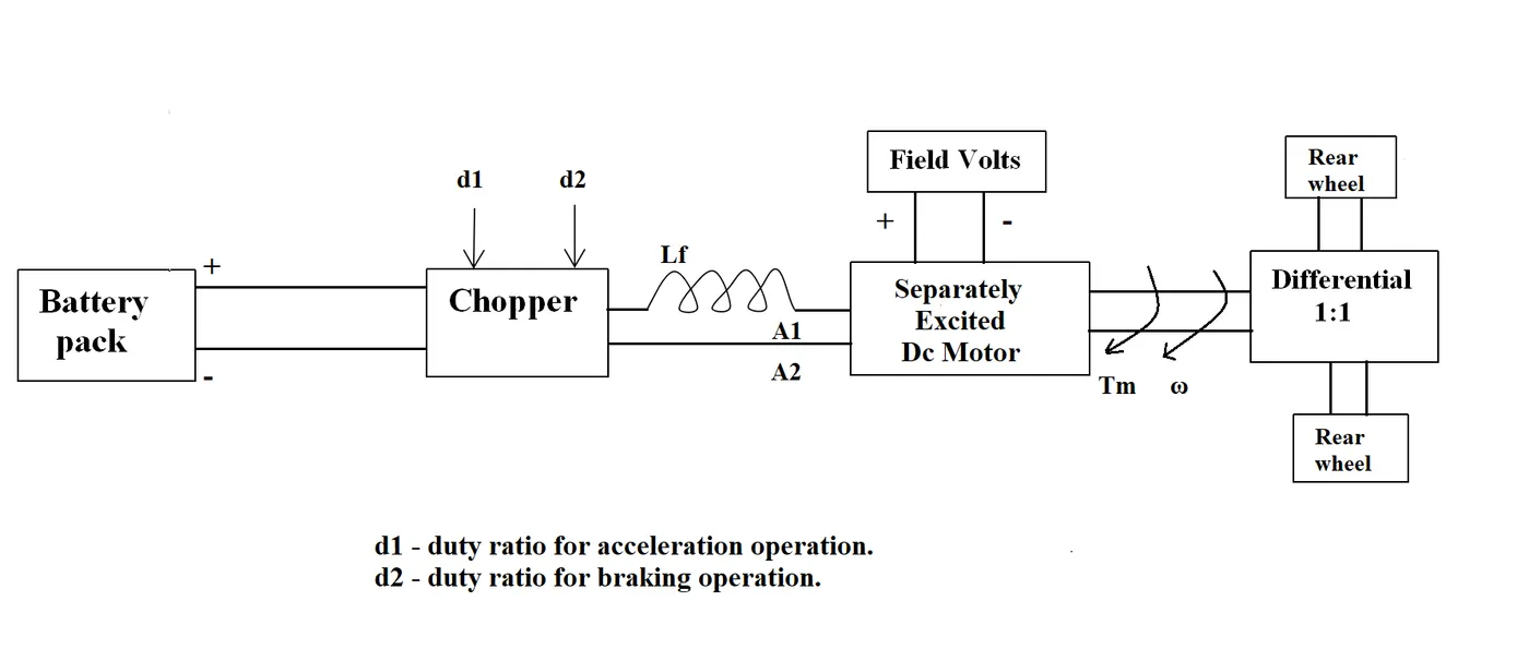
The other parameters of the electric vehicle are given below,
Motor and Controller Parameters:
Rated Armature voltage= 72 V
Rated armature current= 400 A
Ra= 0.5Ω, KΦ= 0.7 Volt second
Chopper Switching frequency= 400 Hz
The vehicle speed-torque characteristics are given by the below equation

What is EV steady-state speed if the duty cycle is 70%?
Given;
Duty cycle = 70% = 70/100 = 0.7
Rated armature voltage = 72V
Let the given relation between speed-torque characteristics
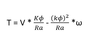 -- equation (A)
Therefore;
Actual/Duty cycle voltage = Duty cycle * Rated armature voltage = 0.7 * 72
Actual voltage = 50.4 V
To calculate the speed= ?
We have the torque equation for the motor is given by;
Substituting all the input values in the above equation;
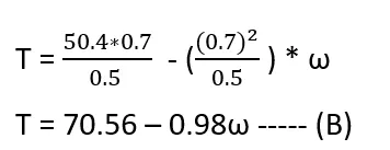
T = 70.56 – 0.98ω ----- (B)
By comparing and solving the torque equation of vehicle (A) and torque equation of motor (B) we get;
24.7 + (0.0051) *ω2 = 70.56 – 0.98ω
0.0051 ω2 + 0.98 ω – 45.86 = 0
The above equation represents a quadratic equation Ax2 + Bx +C = 0
Hence by solving we get;
ω= 38.915 rad/sec and ω = -231.072 rad/sec
taking the positive value of ω;
Hence the EV steady state speed ω = 38.915 rad/sec
i.e; 38.915 * 60/2*3.14
ω = 371 rpm
ω = 38.915 rad/sec = 371rpm
3. Develop a mathematical model of a DC Motor for the below equation using Simulink.
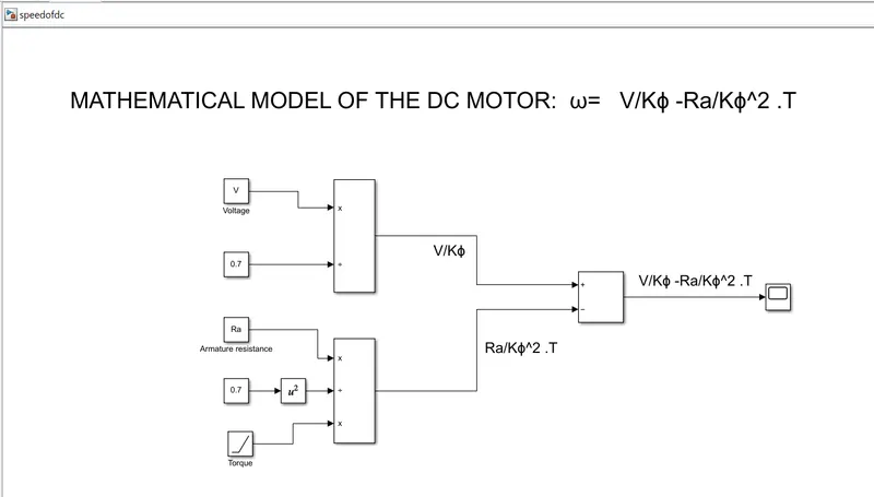
Model link:
OUTPUT:
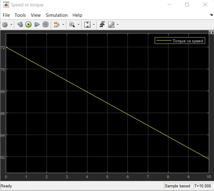
From the plot, it is clear that the greater the torque lesser will be the speed of the motor.
4. To study and explain the concept of Induction Versus DC brushless motors by Wally Rippel, Tesla
Wally tippel perspective was on advancements happening in the EV technology and the telling no particular motor will fulfill all the requirements. With his experience, he was sharing the changes that happened in the battery technology where lead-acid batteries were replaced with Lithium-ion batteries, Brushed DC motors were replaced with a Brushless DC motor or Induction motor, and Contactors used previously were replaced with inverters in the present-day world.
With brushless machines, the rotor includes two or more permanent magnets that generate a DC magnetic field.
This magnetic field enters the stator core and interacts with currents flowing within the windings to produce a torque interaction between the rotor and stator. As the rotor rotates, it is necessary that the magnitude and polarity of the stator currents be continuously varied such that the torque remains constant and the conversion of electrical to mechanical energy is optimally efficient.
The device that provides this current control is called an inverter. Without it, brushless motors are useless motors.
Unlike the DC brushless rotor, the induction rotor has no magnets -just stacked steel laminations with buried peripheral conductors that form a "shorted structure." Currents flowing in the stator windings produce a rotating magnetic field that enters the rotor.
In turn, the frequency of this magnetic field as "seen" by the rotor is equal to the difference between the applied electrical frequency and the rotational "frequency" of the rotor itself. Accordingly, an induced voltage exists across the shorted structure that is proportionate to this speed difference between the rotor and electrical frequency. In response to this voltage, currents are produced within the rotor conductors that are approximately proportionate to the voltage, hence the speed difference.
Finally, these currents interact with the original magnetic field to produce forces- a component of which is the desired rotor torque. He explains the torque produced by the two motors.