Week-6 Challenge: EV Drivetrain
Week 6 Challenge - EV Drivetrain
1. Which types of power converter circuits are employed in electric and hybrid electric vehicle?
Power electronic converters are employed in almost every aspect of daily life, whether at home, at work, or in an industrial setting.These converters have become a vital part of industrial electric drives, high electric power supplies, electric traction systems, and vehicle control devices due to their high power handling and higher efficiency.
Power electronic converters range in size from a few milliwatts to a few thousand watts and are used for a variety of applications (such as inversion, rectification, and so on).
Power electronic technology is concerned with the processing and control of electrical energy flow in order to provide voltages and currents that are best suited to the needs of end users.
SCRs, TRIACs, IGBTs, and other power electronic components are used to control and convert electric power in a power electronic converter. The converter's primary goal is to generate conditioned power for a specific application.
Power electronic converters are classified into the following types based on the function they perform.
Rectifier (AC to DC): It transforms AC current to unipolar (DC) current.
Reverse Inverter: It converts DC to AC at the frequency and voltage you specify.
DC to DC conversion It converts constant DC to variable DC or variable DC to constant DC.
Switch mode power supplies (SMPS), electrical machine control, energy storage systems, lighting drives, active power filters, power generation and distribution, renewable energy conversion, flexible AC transmission, and embedded technology all use these sorts of power electronic converters.

AC – DC Converter: In PHEVs and PEVs, AC to DC converters are most generally employed. These vehicles obtain their propulsion power from an alternating current electricity source, such as recharge stations. A direct current source is required to charge the battery. In a PHEV and PEVs, an AC to DC converter is used for this purpose.
DC- DC Converter: A Battery Electric Vehicle's (BEV) batteries typically produce several hundred volts of Direct Current (DC). However, the voltage needs of the electric components inside the car vary, with the majority of them operating at a significantly lower level. The radio, dashboard readouts, air conditioning, and in-built computers and displays are all included.
A DC-to-DC converter is a type of power converter that converts a DC source to a different voltage level. It can be unidirectional (only transmitting power in one direction) or bidirectional (transmitting power in both directions). Furthermore, a DCDC converter is an important part of a BEV's architecture, as it is utilized to convert power from the high voltage (HV) bus to the 12V Low Voltage (LV) bus to charge the battery and power the onboard electric devices.
DC- AC Converter: The DC to AC converter is needed to transform the DC power into an AC power that the electrical machine can use. The power produced from the battery pack is transformed to electric motor power using an inverter.
2. An Electric Vehicle's powertrain with 72V battery pack in shown in the diagram below. The duty ratio for acceleration operation is 'd1' and for the braking operation the duty ratio is 'd2'.
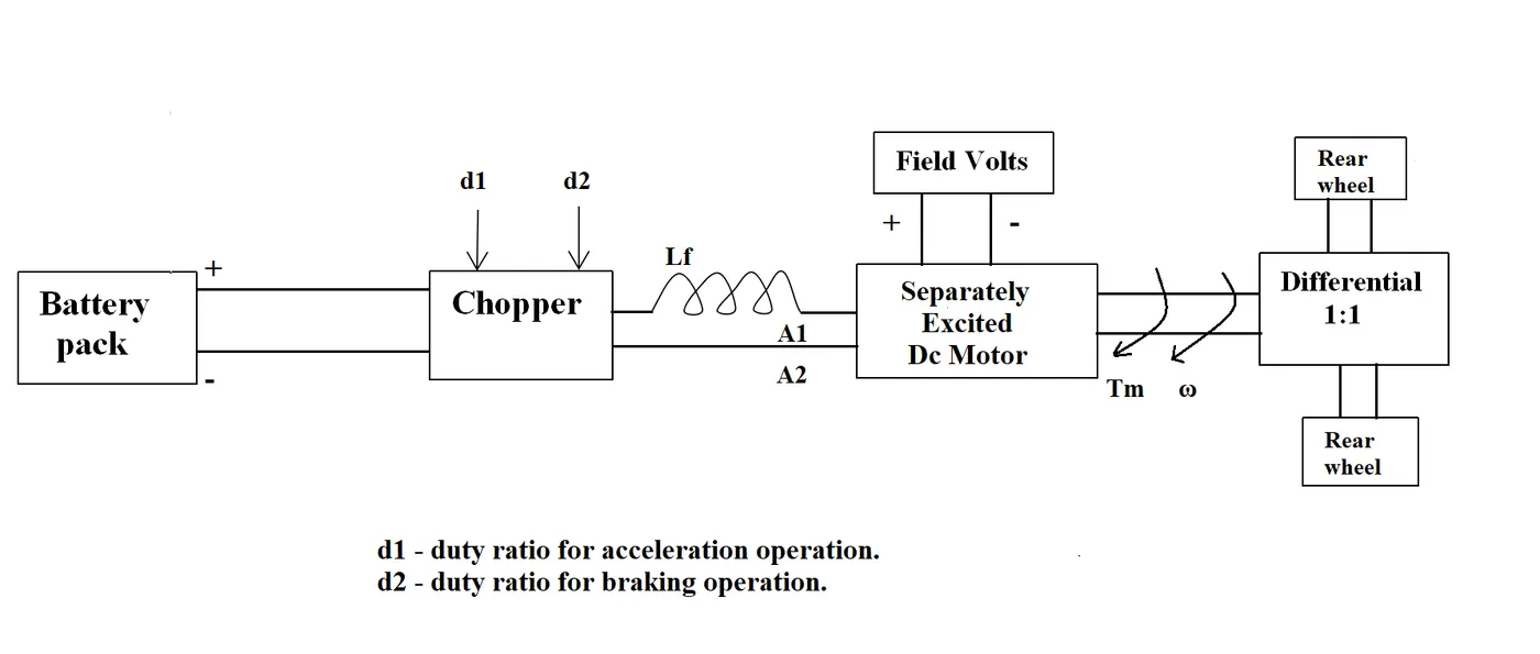
The other parameters of the electric vehicle is given below,
Motor and Controller Parameters:
Rated Armature voltage= 72 V
Rated armature current= 400 A
Ra= 0.5Ω, KΦ= 0.7 Volt second
Chopper Switching frequency= 400 Hz
The vehicle speed-torque characteristics are given by the below equation

What is EV steady state speed if duty cycle is 70%?
Duty cycle = 70%
Therefore, Voltage = Armature voltage x Duty cycle = 72 x 0.7 = 50.4V
The speed of the motor can be written as
Motor speed= (Armature voltage/ motor constant) - ((Armature resistance/ (Motor constant)^2) x Torque)
ω= V/Kϕ -Ra/Kϕ^2 .T
For Torque equation,
T = - ωKϕ^2 /Ra + VKϕ /Ra
T = - ω (0.7)^2/0.5 + 50.4 x 0.7 /0.5
T = - 0.98 ω + 70.56 ------------ (1)
--------- (2)
By equating both the equations
-0.98 ω + 70.56 = 24.7 + (0.0051) ω^2
0.0051 ω^2 + 0.98ω - 45.86 = 0
On Dividing by 0.0051 we get,
ω= 38.91rad/sec & ω = -231.0718 rad/sec
Therefore the speed of the EV is ω= 38.91 rad/sec
3. Refer to the blog on below topic:
Induction Versus DC brushless motors by Wally Rippel, Tesla
Explain in brief about author’s perspective.
Engines are not all the same in the dreadful world of gas-powered automobiles. Flat-heads, Hemis, straight, opposed, and V layouts are all available. It goes on and on. Years ago, one would think that someone would have worked out which was the greatest. That would have put an end to all of the options, and only the best engine type would be produced after that. That is not the case. There is no one best engine type, rather there are numerous sorts of engines to fit personal criteria, such as price and performance. This is also true for driving an electric vehicle.
Brushless machines have two or more permanent magnets in the rotor that generate a DC magnetic field (as seen from the vantage point of the rotor). This magnetic field then enters the stator core (a core made up of thin, stacked laminations) and interacts with currents flowing within the windings to produce rotor-stator torque interaction. The size and polarity of the stator currents must be continuously adjusted – and in just the correct way – while the rotor rotates, so that the torque remains constant and the conversion of electrical to mechanical energy is as efficient as possible. An inverter is the device that offers this current regulation. Brushless motors would be useless if they didn't have it.
Now we'll look at induction motor drives. Nikola Tesla invented a precursor to the three-phase induction motor before 1889. Surprisingly, the stators for 3-phase induction and DC brushless motors are nearly identical. Within the stator core of both, three sets of "distributed windings" are introduced. The rotor is the main difference between the two devices.
The induction rotor, unlike the DC brushless rotor, has no magnets, instead relying on stacked steel laminations with buried peripheral conductors to form a "shorted structure." A revolving magnetic field enters the rotor as currents pass through the stator windings. The difference between the applied electrical frequency and the rotational "frequency" of the rotor equals the frequency of this magnetic field as "perceived" by the rotor. As a result, an induced voltage exists across the shorted structure that is proportional to the rotor speed and electrical frequency difference. The rotor conductors create currents that are approximately proportional to the voltage in reaction to this voltage, resulting in the speed differential.
While 3-phase induction motors provide a lot of advantages, they also have a lot of drawbacks. They can't run on DC; AC is required. Line frequency is proportional to shaft speed. As a result, they are constant speed machines when powered by utility electricity. Finally, when compared to DC type machines, they have reduced beginning torque and running peak torque capabilities when operated off utility power.
With the addition of an inverter (without any feedback control), an induction machine can be powered by a battery or other DC source, and variable speed can be achieved simply by modifying the inverter frequency. However, as compared to DC machines, torque performance is still lacking. When feedback loops are added to ensure that the inverter generates the exact frequency that the motor "desires," the induction motor may now compete with DC and DC brushless motors in vehicle applications.
Motors with comparable stators are used in both DC brushless and induction drives. Three-phase modulating inverters are used in both drives. The rotors and inverter controls are the only modifications. The only control variations with digital controllers are in the control code. (An absolute position sensor is required for DC brushless drives, whereas induction drives just require a speed sensor; the variations are minor.) One of the most significant distinctions is that the DC brushless drive generates significantly less rotor heat. This drive has a simpler rotor cooling system and a greater peak point efficiency. The DC brushless drive can also operate at unity power factor, whereas the induction drive's greatest power factor is around 85%.
Induction machines, on the other hand, do not need magnets and have "adjustable" B fields since B is proportional to V/f (voltage to frequency). This means that during low loads, the inverter can lower the voltage, reducing magnetic losses and increasing efficiency. Thus, when used with a smart inverter, an induction machine has an advantage over a DC brushless machine in that magnetic and conduction losses can be swapped to improve efficiency. As performance improves, this advantage becomes more crucial. When using a DC brushless motor, the magnetic losses increase proportionately as the machine size expands, and part load efficiency decreases. With induction, losses do not necessarily increase as machine size increases. When high performance is required, induction drives may be the best option; peak efficiency will be slightly lower than DC brushless, but average efficiency may be higher.
Induction drives will likely continue to dominate the high-performance pure electrics market, while DC brushless drives will likely continue to dominate the hybrid and impending plug-in hybrid industries. What will happen as hybrids become more electrically intensive and their performance levels increase, is the question. Because so much of the technology is shared across the two drives, it's possible that induction and DC brushless may coexist in the future golden age of hybrid and electric automobiles.