Week-6 Challenge: EV Drivetrain
1.Which types of power converter circuits are employed in electric and hybrid electric vehicle?
Answer:
As the focus in vehicular technology shift toward replacing more and more mechanical, hydraulic or pneumatic systems by electrical systems, power electronics circuits (PECs) have gained a lot of importance in the last decade. Increasing vehicular loads such as utility, entertainment, luxury and safety loads have increased the demand for compact and efficient PECs. The electric components inside the vehicle, however vary in their voltage requirement, with most running on a much lower voltage. This include radio, dashboard readouts, air conditioning and in-built computers and displays.
The converters used in the electric and hybrid electric vehicles are:
- DC-DC converter (chopper): use to supply DC power to auxiliary like radio and car headlights
- DC-AC converter (inverter): use to supply power to motor
- AC-DC converter (rectifier): use in EV charger
DC-DC converter
High-frequency electronic power processors are used in dc-dc power conversion. The functions of dc-dc converters are:
- to convert a dc input voltage VS into a dc output voltage VO;
- to regulate the dc output voltage against load and line variations;
- to reduce the ac voltage ripple on the dc output voltage below the required level;
- to provide isolation between the input source and the load (isolation is not always required);
- to protect the supplied system and the input source from electromagnetic interference (EMI); and
- to satisfy various international and national safety standards.
The DC-DC converter include various converter topologies.
Buck Converter:
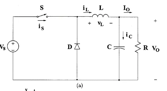
The buck converter circuit diagram is shown in the figure below. The buck converter produces average output voltage less than input DC voltage.
It consists of DC input voltage source , controlled switch S, diode D, filter inductor L, filter capacitor C and load resistance R.
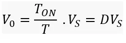
The average output voltage is given by:
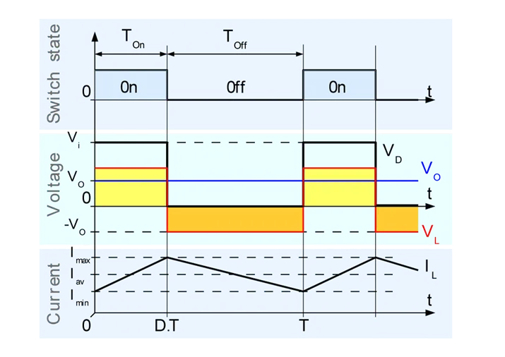
The above diagram shows the waveform for the buck converter under the assumptions that the inductor current is always positive. That means it is operating under continuous conduction mode. It shows that the output voltage is less than the input voltage.
Boost Converter:
The boost converter produces the output voltage greater than the input DC voltage. The figure given below shows the circuit diagram of the boost converter.
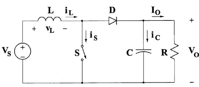
It consists of a DC input voltage source , boost inductor L, controlled switch S, diode D, filter capacitor C and load resistance R.
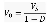
The average output voltage is given by:
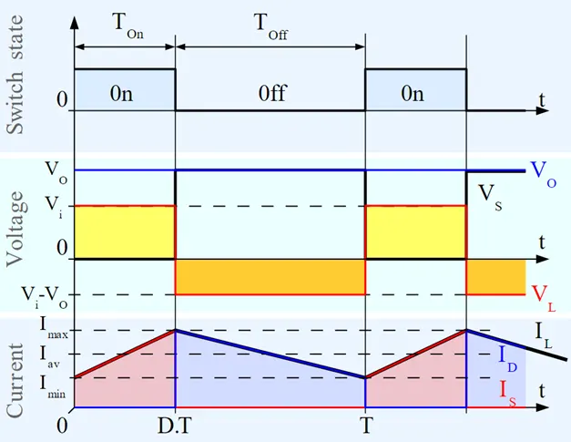
The above diagram shows the waveform for the boost converter under the assumptions that the inductor current is always positive. That means it is operating under continuous conduction mode. It shows that the output voltage is greater than the input voltage.
Buck-Boost Converter:
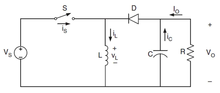
The boost converter produces the output voltage either greater than or less than the input DC voltage. The figure given below shows the non-isolated topology of the buck-boost converter. It is equivalent to flyback converter using a single inductor instead of a transformer.
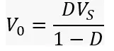
The average output voltage is given by:
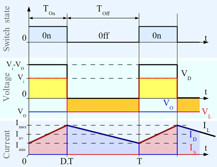
The above diagram shows the waveform for the buck-boost converter under the assumptions that the inductor current is always positive. That means it is operating under continuous conduction mode. It shows that the output voltage is either greater than or less than the output voltage.
The amount of power flow between the input and the output can be controlled by adjusting the duty cycle (ratio of ON/OFF time of the switch).
Usually this is done to control the output voltage, input current, output current or to maintain constant power.
DC-AC converters (inverter)
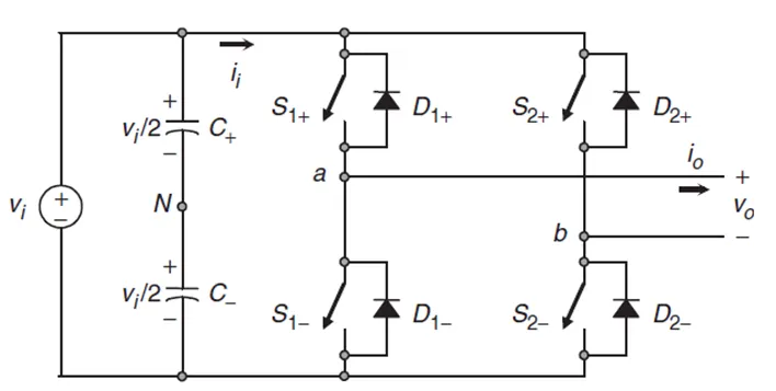
An inverter is a device that converts DC power from the battery to AC power used in an electric motor vehicle. The inverter can change the speed at which the motor rotates by adjusting the frequency of the alternating current.
The following figure shows the circuit diagram of the single phase voltage source inverter.
The figure below shows how input DC voltage waveform is converted into the output AC voltage.
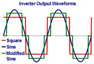
There are different types of inverters based on the shape of the switching waveform. These have varying circuit configurations, efficiencies, advantages and disadvantages
The use of inverters can increase or decrease the power or torque of the motor by adjusting the amplitude of the signal.
It plays a significant role in capturing energy from regenerative braking and feeding it back to the battery.
The key component is that it has direct impact on on-road performance, driving range and reliability of the vehicle also as a consequence of their weight and size.
The output voltage waveform of an ideal inverter should be sinusoidal. However, the waveform of practical inverters are non-sinusoidal and contains certain harmonics.
AC to DC Converters (Rectifier):
AC to DC Converters are one of the most important in power electronics because there are lot of real applications are based on this conversions. The AC current to dc current conversion process is known as rectification. This rectifier converts AC supply into the DC supply at load end connection. Normally Transformers are used to adjust the AC source to get step down transformer to reduce the voltage level to have better operation range for DC supply. Normally this AC to DC converter converts low voltage values.
Uncontrolled converter converts fixed DC voltage, it means the value of output for a given value of AC voltage. Fully controlled converter convert adjustable DC voltage when the adjustable range can adjust in both positive and negative side. Semi-controlled converter also produce an adjustable DC voltage which positive side power.
All three converter have unidirectional power flow on AC side to DC side. PWN converter can produce adjustable both positive importantly it allows power flow in either direction. Making it ideal application motor drives and power system interconnection with the power system.
All three converter have unidirectional power flow on AC side to DC side. PWN converter can produce adjustable both positive importantly it allows power flow in either direction. Making it ideal application motor drives and power system interconnection with the power system.
In here we are first going to explain more about the uncontrolled rectifiers. Uncontrolled rectifiers can also subdivide into several subcategories such as
- Single phase half wave rectifier
- Single phase full wave bridge rectifier
- Single phase center tapped full wave rectifier
- Three phase half wave diode rectifier
2. An Electric Vehicle's powertrain with 72V battery pack in shown in the diagram below. The duty ratio for acceleration operation is 'd1' and for the braking operation the duty ratio is 'd2'.
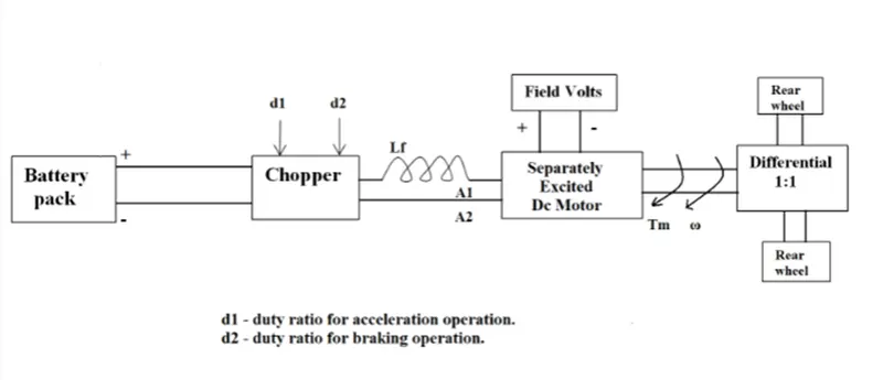
The other parameters of the electric vehicle is given below,
Motor and Controller Parameters:
Rated Armature voltage = 72 V
Rated armature current = 400 A
Ra = 0.5 Ω, KΦ = 0.7 Volt second
Chopper Switching frequency = 400 Hz
The vehicle speed-torque characteristics are given by the below equation

What is EV steady state speed if duty cycle is 70%?
Answer:
Average output voltage = Battery voltage * duty cycle
= 72 * 0.70
= 50.4 V
Torque speed characteristics of the DC motor is given by:
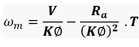
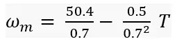

 ………………………………………………………………(1)
The vehicle speed torque characteristics is given as
.....................................................................(2)
Putting the equation (1) in the equation (2)
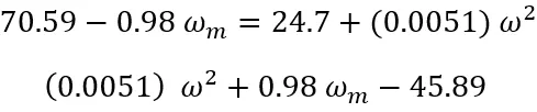
The solution for the quadratic equation
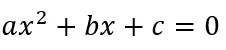
Is given by
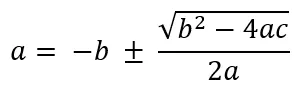
We get w = 38.94 rad/sec and w = - 231.09 rad/sec
Thus the EV steady state speed is 38.94 rad/sec.
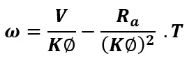
3.Develop a mathematical model of a DC Motor for the below equation using Simulink
Answer:
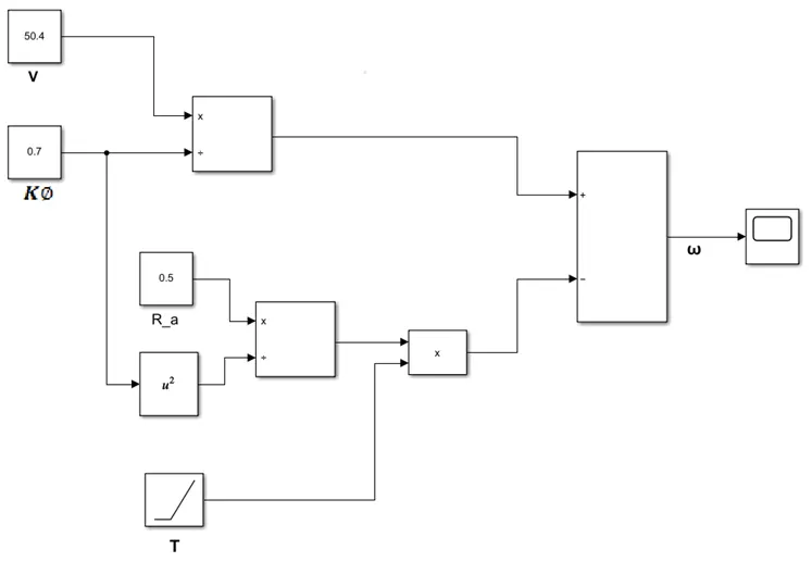
Keeping all the parameters as given above:
V = 50.4 V
 = 0.5 ohm
`Kphi` = 0.7 volt second
The mathematical model of the DC motor is:
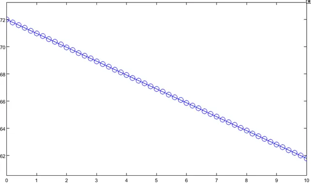
Results:
4. Refer to the blog on below topic:
https://www.tesla.com/blog/induction-versus-dc-brushless-motors
Explain in brief about author’s perspective.
Answer:
- Wally Rippel is a long-time proponent of electric vehicles. Prior to joining Tesla Motors, he was an engineer at AeroVironment, where he helped develop the EV1 for General Motors and was featured in the documentary movie, Who Killed the Electric car? Wally has also worked for the Jet Propulsion Laboratory on electric vehicle battery research, among other projects. In 1968, as a Caltech undergraduate student, he built an electric car (a converted 1958 Volkswagen microbus) and won the Great Transcontinental Electric Car Race against MIT.
- The author is sharing his view on the varying technologies in the vehicle domain. Talking about our conventional or gas powered vehicles, there is no one best engine type. There are different type of engines and that can suit a particular type of vehicles depending upon the vehicle performance, price and other personal requirement. The same thing applies to the electrical and hybrid electrical vehicles.
- He has seen various technologies changing over the decades from lead acid batteries, DC brushed motors to contactor controllers. As lead acid batteries are replace by the lithium, DC motors are either by DC brushless or induction motors, contactors are replaced by modulating inverters. So he is concluding that it is absolutely hard to predict the future.
- He is differentiating the DC brushless motors with the induction motors to find out which one is better. He starts with DC brushless motor, permanent magnets are used to produce rotating magnetic field to induces the current in the conductor. The mmf is produce and rotor continue to rotate. As during the operation of the motor, it is necessary that both the magnitude and polarity of the stator currents should be continuously varied. Torque should be constant and electrical to mechanical conversion is optimally efficient. This can be done by the inverter and motor. The inverter is most important part in the DC brushless motor.
- He later explains about the induction motor which was invented by Nikola Tesla before 1889. Both motors have same stator arrangement which have three sets of distributed windings. The main difference between this two is rotor.
- Induction motor rotor does not have magnets as it has stacked steel laminations with buried peripheral conductors which form a shorted structure.
- The current is supplied to the stator of the induction motor that generate emf and rotor continue to rotate due to the speed difference created between the rotor and stator magnetic field.
- The induction motors are successful because they are compatible with conventional power utility. The torque is produced when it is directly connected to the load. While brushless DC motor requires inverter to produce starting torque as it maintains its step in phase with the angular position of the rotor.
- One of the main differences is that less rotor heat is generated with the DC brushless drive. Rotor cooling is easier and peak point efficiency is generally higher for this drive. It is mentioned that the brushless DC drive operate at unity power factor whereas the best power factor for the induction motor is about 85%.
- In case of brushless DC motor, the strength of the magnetic field is adjustable. When at low speed the maximum torque is required. Magnetic field should be maximum i.e. inverter and motor current maintained at their lowest optimum efficiency. Whereas there is no such adjustment in case of induction motor.
- As the machine size increases, the magnetic losses increases proportionally and part load efficiency decreases. In case of induction motor, as the machine size increased the losses do not necessarily increases.
- Speed of the induction motor is depends upon the input frequency which is difficult to control.
- The construction of brushless DC motor is costlier as compared to the induction motor due to permanent magnet.
Conclusion:
- The author conclude that the DC brushless drives are best fit for the hybrid and plug-in hybrid vehicles. In the high performance pure electric vehicles, the induction motor drives will continue to maintain dominance. As so much hardware is common in both DC brushless and induction motor drives so we will see both the drives working side by side in the hybrid and pure electric vehicles.