Week-6 Challenge: EV Drivetrain
TYPES OF POWER CONVERTERS IN HEV& PURE EV……
- AC-DC CONVERTER RECTIFIER
- DC-DC CONVERTER CHOPPER
- DC-AC CONVERTER INVERTER
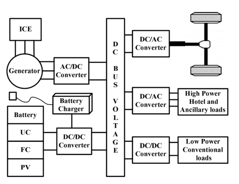
AC-DC CONVERTER RECTIFIER
AC-DC conversion is widely used in several applications such as changing speed drivers, switch mode power supplies, uninterrupted power supplies and battery energy storage.
AC-DC converters, popularly noted to as rectifier, are introduced to using diodes and thyristor to give uncontrolled and controlled dc power with unidirectional and bidirectional power flow.
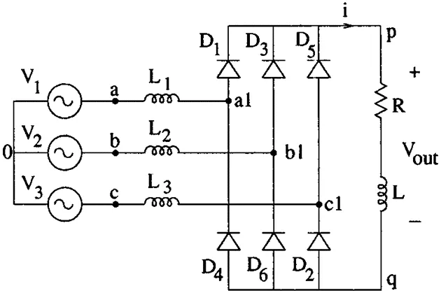
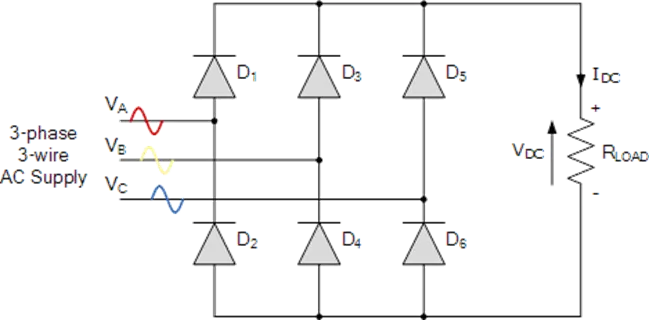
The top group diodes (D1, D3, D5) form a “Maximum value circuit” and therefore the maximum of the phase voltages van, vbn, vcn appears at the positive dc bus.
Operation of the converter can be explained as follows
On the other hand, the bottom group diodes (D2, D4, D6) form a “Minimum value circuit”. Therefore, the minimum of the phase voltages van, vbn and vcn appears at the negative dc bus.
Therefore, the output voltage waveform at any instant is equal to the maximum of the six-line voltages vab, vbc, vca, vba, vcb and vac provided at least one diode from the top group and one from the bottom group conducts at that instant.
None of the diodes will conducts, however if the output capacitor voltage is larger than the maximum line voltage.
All the six operating modes of a 3-phase bridge rectifier namely, D1D2, D2D3, D3D4, D4D5, D5D6 and D6D1 appear in that order.
In addition, an additional operating mode in which none of the diodes conduct appears in the conduction diagram as shown in Fig. 12.3 (b).
During these periods the output capacitor discharges through the load.
As the capacitor voltage decreases its voltage becomes equal to the incoming line voltage.
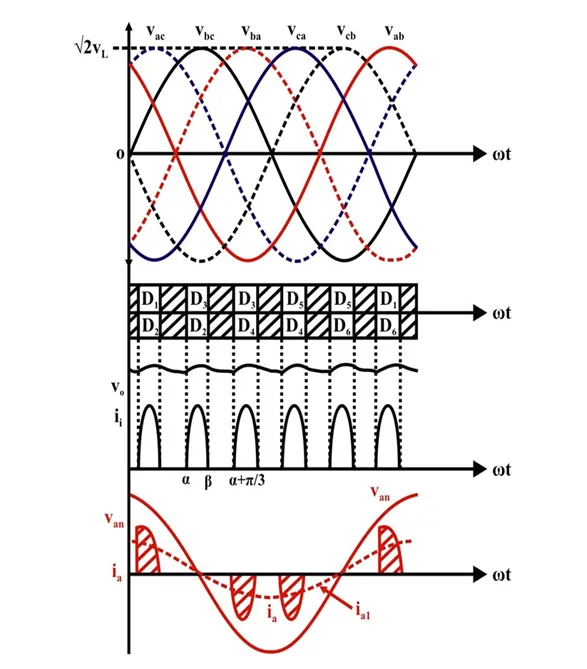
At this instant the appropriate diodes from both the top and the bottom group starts conducting and continuous to do so till the sum of the capacitor charging current and the load current becomes zero.
DC-DC CONVERTER CHOPPER
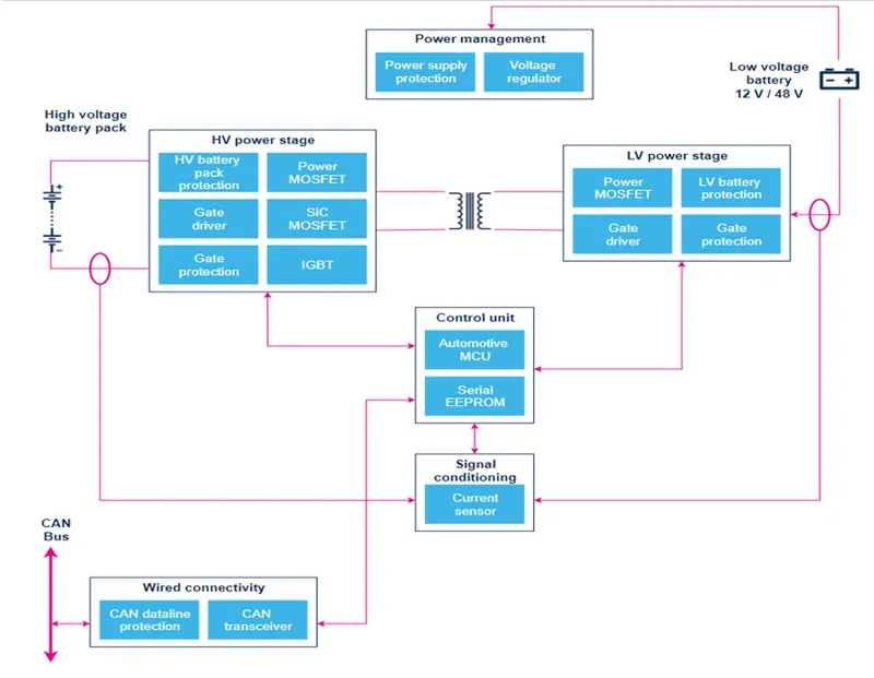
In electric engineering, a DC-to-DC converter is a category of power converters and it is an electric circuit which converts a source of direct current (DC) from one voltage level to another, by storing the input energy temporarily and then releasing that energy to the output at a different voltage.
The storage may be in either magnetic field storage components (inductors, transformers) or electric field storage components (capacitors).
DC/DC converters can be designed to transfer power in only one direction, from the input to the output.
However, almost all DC/DC converter topologies can be made bi-directional. A bi-directional converter can move power in either direction, which is useful in applications requiring regenerative braking.
The amount of power flow between the input and the output can be controlled by adjusting the duty cycle (ratio of on/off time of the switch).
Usually, this is done to control the output voltage, the input current, the output current, or to maintain a constant power.
Transformer-based converters may provide isolation between the input and the output.
The main drawbacks of switching converters include complexity, electronic noise and high cost for some topologies.
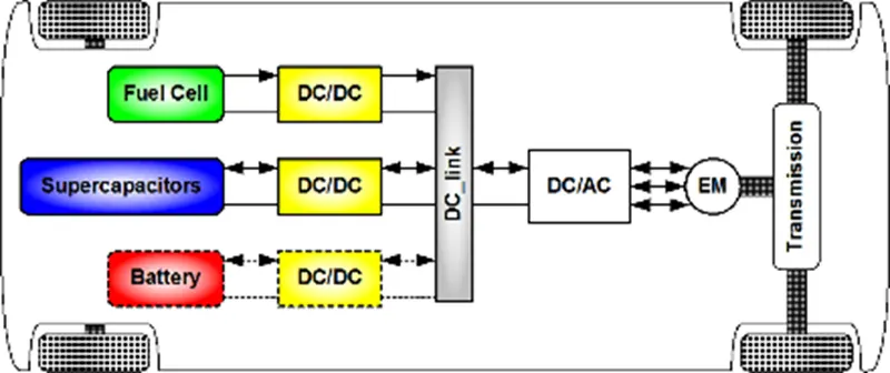
DC-AC CONVERTER INVERTER
An inverter is a device that converts DC power to the AC power used in an electric vehicle motor.
The inverter can change the speed at which the motor rotates by adjusting the frequency of the alternating current.
It can also increase or decrease the power or torque of the motor by adjusting the amplitude of the signal.
EV traction inverters must provide high power – in the range of 80 to 200+ kW- to the traction motor, withstand high temperatures and be as small and as light as possible.
Key performance parameters for inverters are high efficiency - for longer battery life, high-power density - for small size and low weight, and high levels of functional safety to protect the vehicle operator and systems.
The inverter converts energy from the high-voltage battery to multiphase AC current to drive the traction motor, which is a 3-phase inductive load.
Electronics in the inverter control this power conversion to the traction motor with highest possible efficiency and reliability and therefore:
- Precisely control, monitor and protect the high-power switches to achieve energy and high reliability
- Accurately and efficiently control the motor speed and torque
- Enable the highest level of functional safety in compliance with ISO 26262 requirements
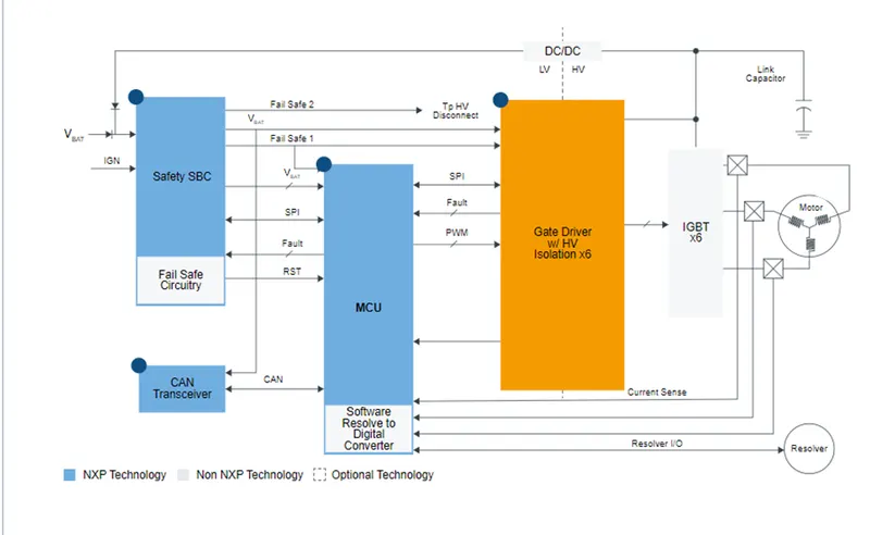
Q.2) An Electric Vehicle's powertrain with 72V battery pack in shown in the diagram below. The duty ratio for acceleration operation is 'd1' and for the braking operation the duty ratio is 'd2'.
The other parameters of the electric vehicle are given below,
Motor and Controller Parameters:
Rated Armature voltage= 72 V
Rated armature current= 400 A
Ra= 0.5Ω, KΦ= 0.7 Volt second
Chopper Switching frequency= 400 Hz
The vehicle speed-torque characteristics are given by the below equation
……………..(1)
What is EV steady state speed if duty cycle is 70%?
SOLUTION:
Switching frequency = 400hz
Tv = 24.7 + (0.0051)w2
Duty cycle = 70%
Output voltage from chopper = 72*(70/100)
V0 = 50.4
Ra = 0.5
Kø = 0.7
Putting all the values of given parameters,
Torque vs Speed Relation,
Tv = [V0 * (Kø) / Ra ] – [w(Kø)2 / Ra ]
Tv = [50.4 * (0.7) / 0.5 ] – [w(0.7)2 / 0.5 ]
Tv = [70.56] – [0.98w]…………………(2)
Equating both the equation, from (1) & (2),
Tv = [70.56] – [0.98w] = [ 24.7 + (0.0051)w2]
0.0051w2 + 0.98w – 45.89 = 0
Solving quadratic equation,
x = -b ± ( b2 – 4ac ) ½
w = -0.98 ± ( 0.982 – 4(0.0051)(-45.89) ½
w = -0.98 ± (1.377)
w = 38.92 rad/sec.
accepting the positive speed result.
Q.3)
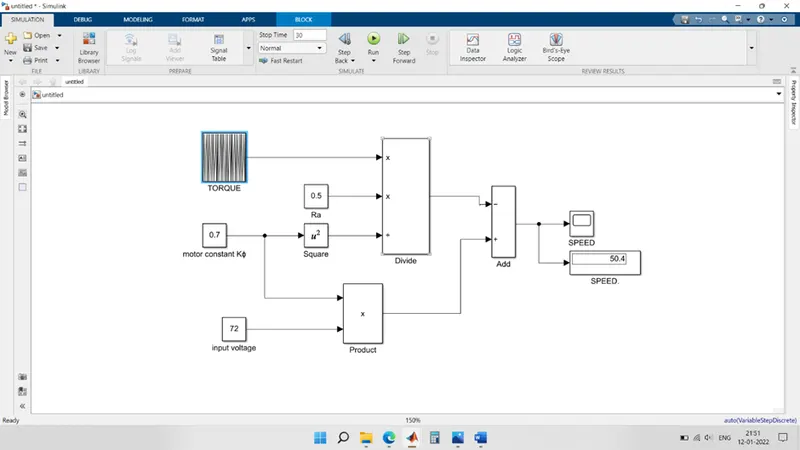
Develop a mathematical model of a DC Motor for the below equation using Simulink.
ω= V/Kϕ -Ra/Kϕ^2 .T
SOLUTION:
As given in statement,
Simulink model is modelled for the given equation of dc motor.
Used Simulink block:
- Constant
- Scope
- Repeating sequence
- Display
- Multiply / division
- Add/subtract
Using constant block, defined the value of input voltage, motor constant, resistance of armature.
And done mathematical calculation of its equation using add and multiply block.
Repeating sequence shows torque parameter.
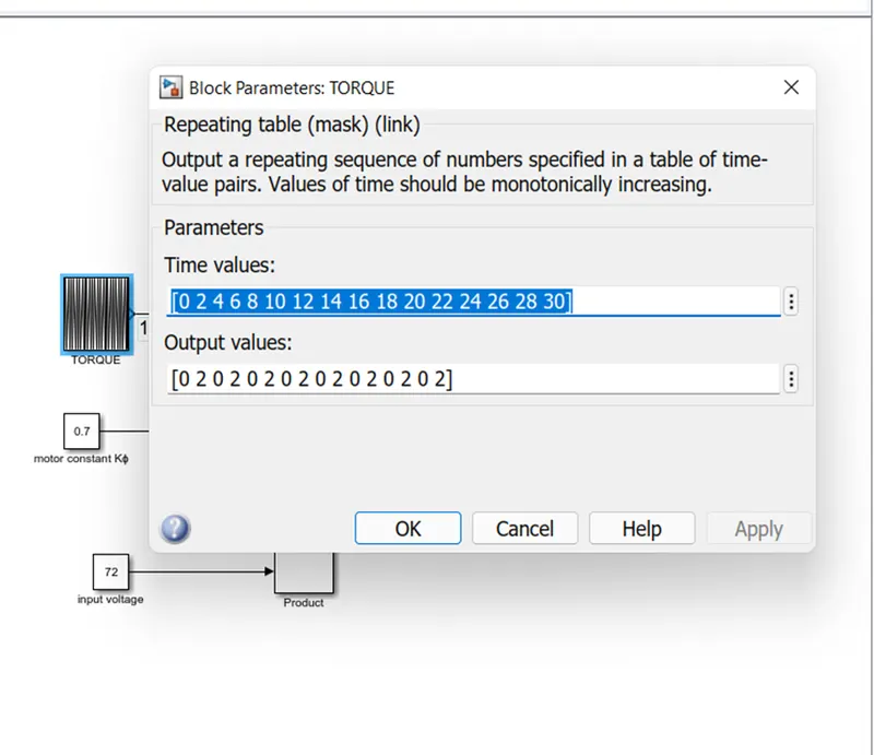
SIMULINK MODEL:
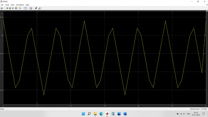
SCOPE OUTPUT OF SPEED:
The output of the speed is shown here.
Q.4) INDUCTION MOTOR vs BLDC MOTOR
- There is no perfect engine yet, but that depends on price & performance.
- Lead acid battery replaced by lithium-ion batteries.
- DC brushed motor replaced by brushless DC motor, induction motor.
- BLDC requires permanent magnets, while induction motor uses stacked steel laminations.
- When a 3-phase induction motor is connected to utility type 3-phase power, torque is produced at the outset; the motor has the ability to start under load. No inverter is needed.
- brushless DC motor produces no starting torque when directly connected to fixed frequency utility power. They really need the aid of an inverter
- The only difference with BLDC & IM are the rotors and the inverter controls.
- BLDC has position sensor, while IM has speed sensor.
- The energy efficiency for a BLDC drive will typically be a higher than for an IM drive
- BLDC drive is more economical and feasible way for future performance of HEV & pure EV.