Project
TO STUDY AL TERRIAN LEVEL VEHICLE SIMULATION.
- An ATV is a small motor vehicle with three or four low pressure tires designed for use on various types of terrain.
- Recreational activities in deserts are usually carried out in ATVs.
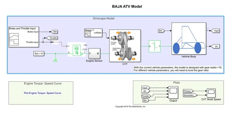
- This project is in reference to one of the types of ATVs used in BAJA SAE competitions.
{BAJA ATV with continuously variable transmission}
- A continuously variable transmission is automatic transmission.
- It is capable of providing more useable power, economy of fuel, best driving experience.
- It is more compatible than usual transmission system.
- It works to provide smooth torque flow with very stepless transmission ratio.
- It is an automatic, single speed, and gearless transmission that can shift through an infinite number of gear ratios.
- Therefore, an infinite number of ratios (between a minimum & maximum value) are possible.
- This ability to seamlessly shift through these different gears provides a number of benefits including extremely smooth engine, which gives driver quick acc. Than standard automatic transmission.
- Because of their ability to control the engine speed, CVTs produce fewer emissions.
- CVTs are also lighter weight than traditional automatic transmissions.
|
SIMULINK blocks USED IN CVT MODELLING |
|
Signal builder |
|
Generic engine |
|
Motion sensors |
|
Vehicle transmission |
|
Vehicle body |
|
Tyres |
|
Solver configuration |
|
Inertia |
|
Ideal rotational sensor |
|
Simple gear |
|
Vehicle gear ratio |
|
Vehicle body |
|
Double shoe brake |
|
Engine sensor |
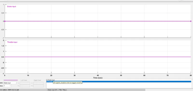
SIGNAL BUILDER:
Using signal builder block, two inputs: 1) throttle
2) brakes are defined.
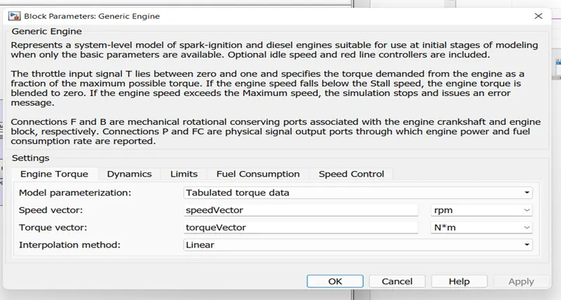
Generic engine:
Represents a system-level model of spark-ignition and diesel engines suitable for use at initial stages of modeling when only the basic parameters are available. Optional idle speed and red line controllers are included.
The throttle input signal T lies between zero and one and specifies the torque demanded from the engine as a fraction of the maximum possible torque. If the engine speed falls below the Stall speed, the engine torque is blended to zero. If the engine speed exceeds the Maximum speed, the simulation stops and issues an error message.
Connections F and B are mechanical rotational conserving ports associated with the engine crankshaft and engine block, respectively. Connections P and FC are physical signal output ports through which engine power and fuel consumption rate are reported.
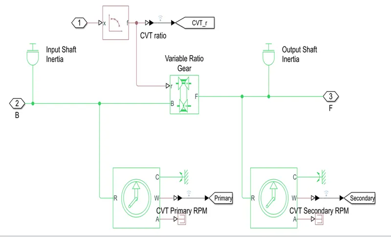
CONTINIOUSLY VARIABLE TRANSMISSION:
Represents a variable ratio gearbox such as implemented by mechanical belt CVT, electric, or hydraulic transmissions.
The physical signal input r defines the ratio of input to output angular shaft velocities.
Connections B (base) and F (follower) are mechanical rotational conserving ports.
Specify the relation between base and follower rotation directions with the Output shaft rotates parameter.
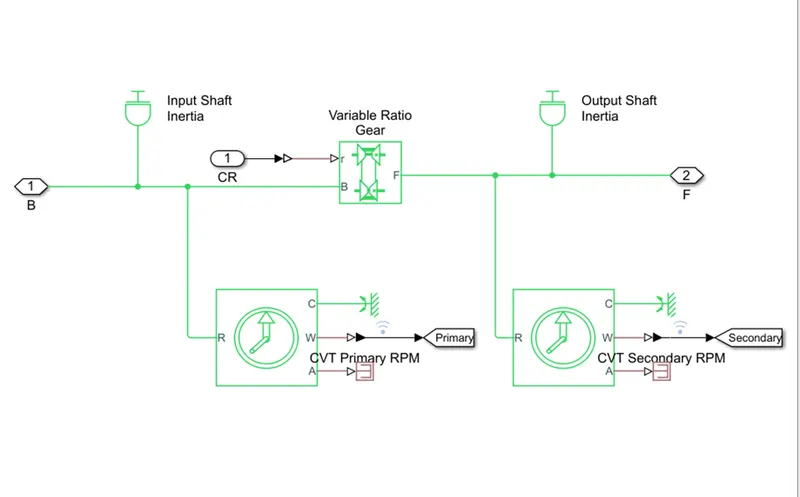
IDEAL ROTATIONAL SENSOR:
This block measures angular velocity or angle in a mechanical rotational network.
The sensor is ideal since it does not account for inertia, friction, delays, energy consumption, and so on.
The physical signal ports W and A report the angular velocity and angle, respectively, of port R relative to port C.
The measured angular velocity is positive when the angular velocity at port R is greater than the angular velocity at port C.
SIMPLE GEAR:
Represents a fixed-ratio gear or gear box. No inertia or compliance is modelled in this block.
You can optionally include gear meshing and viscous bearing losses.
Connections B (base) and F (follower) are mechanical rotational conserving ports.
Specify the relation between base and follower rotation directions with the Output shaft rotates parameter.
Optionally include thermal effects and expose thermal conserving port H by setting Friction model to a temperature-dependent setting.
VEHICLE BODY:
Represents a two-axle vehicle body in longitudinal motion.
The block accounts for body mass, aerodynamic drag, road incline, and weight distribution between axles due to acceleration and road profile.
The vehicle can have the same or a different number of wheels on each axle. Optionally include pitch and suspension dynamics or additional variable mass and inertia.
The vehicle does not move vertically relative to the ground.
Connection H is the mechanical translational conserving port associated with the horizontal motion of the vehicle body.
The resulting traction motion developed by tires should be connected to this port.
Connections V, NF, and NR are physical signal output ports for vehicle velocity and front and rear normal wheel forces, respectively.
Wheel forces are considered positive if acting downwards. Connections W and beta are physical signal input ports corresponding to headwind speed and road inclination angle, respectively.
If variable mass is modelled, the physical signal input ports CG and M are exposed. CG accepts a two- element vector representing the x and y distance offsets from vehicle CG to additional load mass CG.
M represents the additional mass. If both variable mass and pitch dynamics are included, the physical signal port J accepts the inertia of the additional mass about its own CG.
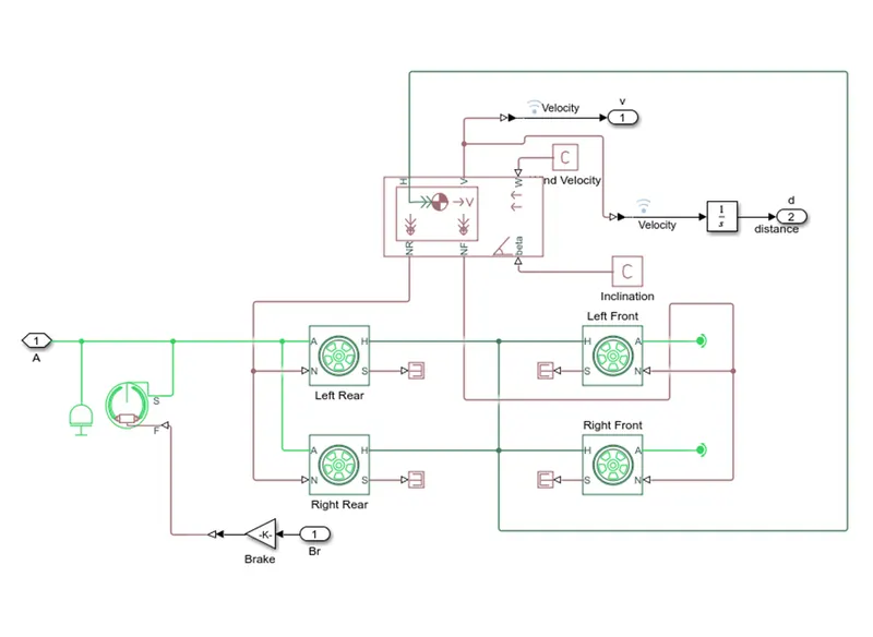
FRONT & REAR TYRE:
Represents the longitudinal behaviour of a highway tire characterized by the tire Magic Formula.
The block is built from Tire-Road Interaction (Magic Formula) and Simscape Foundation Library Wheel and Axle blocks.
Optionally, the effects of tire inertia, stiffness, and damping can be included.
Connection A is the mechanical rotational conserving port for the wheel axle.
Connection H is the mechanical translational conserving port for the wheel hub through which the thrust developed by the tire is applied to the vehicle.
Connection N is a physical signal input port that applies the normal force acting on the tire. The force is considered positive if it acts downwards.
Connection S is a physical signal output port that reports the tire slip. Optionally expose physical signal port M by setting Parameterize by to Physical signal Magic Formula coefficients.
Physical signal port M accepts a four-element vector corresponding to the B, C, D, and E Magic Formula coefficients
{BAJA ATV CVT with DASHBOARD}
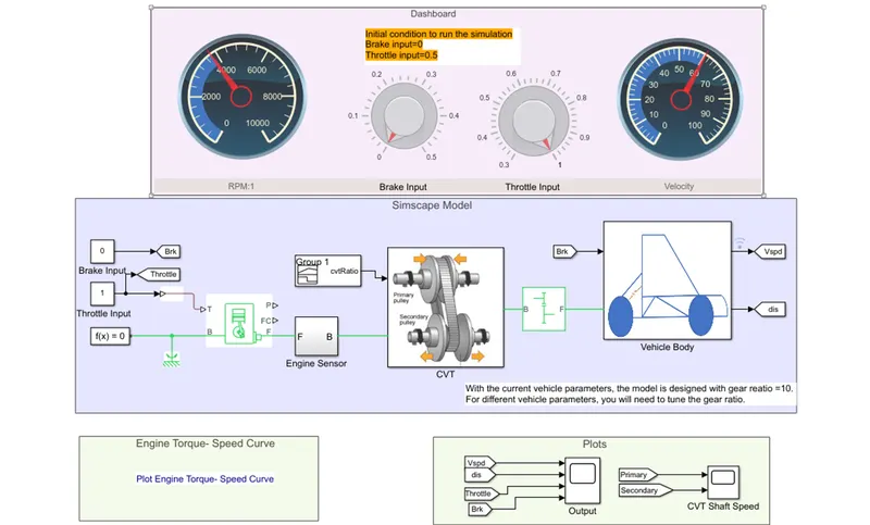
ATV with dashboard model have throttle and brake input in the dashboard.
By using the knob, throttle and brake can be varied live and visual result can be observed using circular gauge.
All other components are as same as the ATV.
|
SIMULINK blocks USED IN CVT MODELLING |
|
Circular gauge |
|
Knob |
|
Signal builder |
|
Generic engine |
|
Motion sensors |
|
Vehicle transmission |
|
Vehicle body |
|
Tyres |
|
Solver configuration |
|
Inertia |
|
Ideal rotational sensor |
|
Simple gear |
|
Vehicle gear ratio |
|
Vehicle body |
|
Double shoe brake |
|
Engine sensor |
{BAJA ATV CVT with DASHBOARD using LOOKUP TABLE}
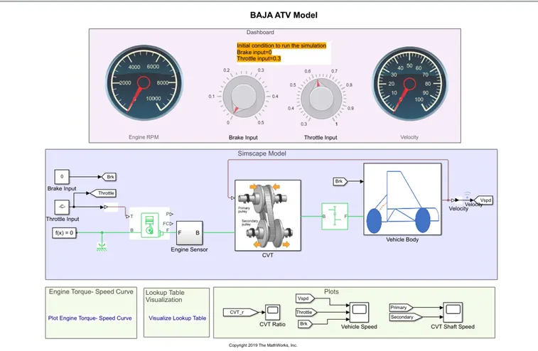
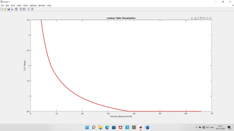
Lookup table: This block represents a physical signal converter whose input-output relationship is specified by a lookup table. The table grid must be in strictly ascending or strictly descending order, but the spacing can be nonuniform.
Right-click on the block and select Foundation Library > Plot Table to visualize the table data based on the selected interpolation and extrapolation methods.
This block does not propagate physical signal units and will be removed in a future release. Use the Upgrade Advisor to update this block to the latest version.
RESULTS:
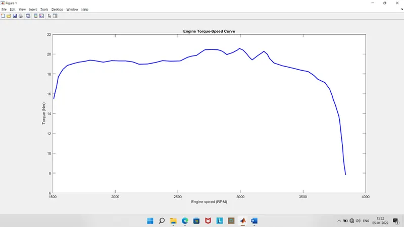
1) ENGINE-TORUQE SPEED CURVE
2)LOOKUP TABLE CURVE
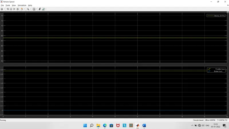
3) THROTTLE INPUT
BRAKE INPUT
VELOCITY OUTPUT
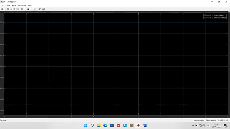
4)CVT PRIMARY RPM
CVT SECONDARY RPM