Week - 4
OBJECTIVE:
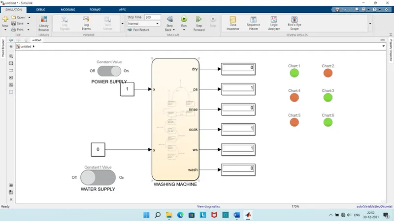
- Implement control logic of a “washing machine” using state flow as per given sequence.
- If power supply is available, system gets activated.
- If water supply is not available, stop the process & indicate through LED.
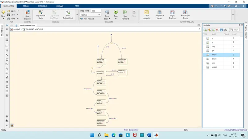
- Soaking time should be 200s followed by washing time of 100s.
- Then rinsing happens for next 20s & dryer runs for 50s.
- After all process, turn ON the LED.
- STATEFLOW MODEL:
- SYMBOL PANE
- EXPLANATION:
State flow provides the graphical language that includes state transition diagrams, flow charts, state transition tables, truth tables.
It is used to describe how MATLAB algorithms Simulink models react to input signals, events and time-based conditions.
Graphical animation enables you to analyse & debug your logic while executing.
Edit time & run time ensures design consistency and completeness before implementation.
Control logic is a key part of software program that controls operation of the program.
The control logic responds to commands from the user & it also acts on its own to perform automated tasks that have been structured into program.
Controlled logic can be modelled using a state diagram, which is a form of hierarchical state machine.
STEPS:
Create chart block for defining state flow as per given conditions.
Inside it, circular junction is to terminate signal flow and return null value.
If power is OFF, the process is terminated.
If water is OFF, the process is terminated.
After this, at 200 sec soak blocks get activated and soaking actions takes place.
After 300 sec of soaking, wash blocks get activated
After 320 sec of washing, rinse block gets activated
After 370 sec of rinsing, dry blocks get activated
After then signal flow in the process and exits the chart.
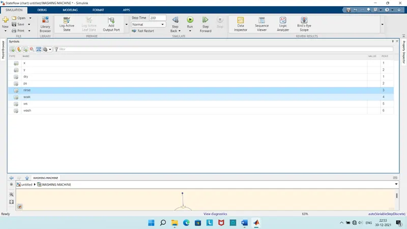
Define power & water as input and soak, rinse, dry, wash, finish as outputs.
A common block is connected to observe the entire process and obtain the output plot.
MODEL DESCRIPTION:
In the above control logic first junction is created with 2 conditions for power supply, one is when power is supplied and second without power supply.
If the power supply at entry level is 1 or ON the machine will get activated & start next process.
After power supply state, water supply.
Next 4 operation states have been created in flow order soaking, washing, rinsing, drying with their time of operation as 200 sec for soak, 100 sec for wash, 20 sec for rinse, 50 sec for dry.
After finishing all the sets of operation, the power supply is changes to PS=0, which leads to shut off machine.
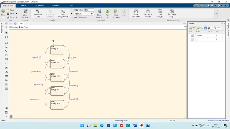
- Make Simulink chart for the “GEAR SHIFT” logic as per below:
|
SPEED |
GEAR |
|
0 to 15 |
1 |
|
16 to 25 |
2 |
|
26 to 40 |
3 |
|
41 to 60 |
4 |
|
Above 61 |
5 |
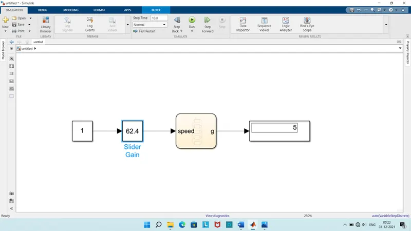
Give speed input while simulation is running & display gear number.
STATEFLOW MODEL:
SYMBOLS PANE:
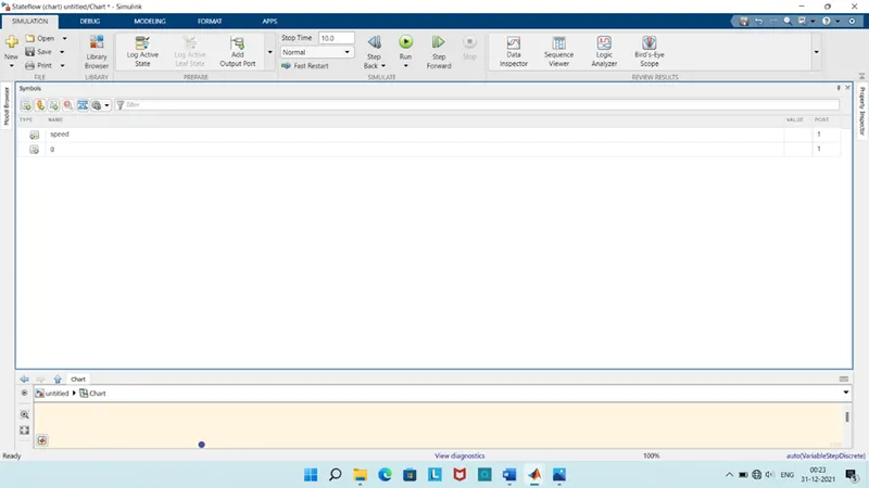
MODEL DESCRIPTION:
Create block for defining the stateflow as given instructions.
If speed is 0 than, the stateflow terminates and gear 0 is activated.
If speed is 15 than, the stateflow terminates and gear 1 is activated.
If speed is 25 than, the stateflow terminates and gear 2 is activated.
If speed is 40 than, the stateflow terminates and gear 3 is activated.
If speed is 60 than, the stateflow terminates and gear 4 is activated.
If speed is greater than 60 than 5 th gear is activated.
RESULT:
GEAR: 1
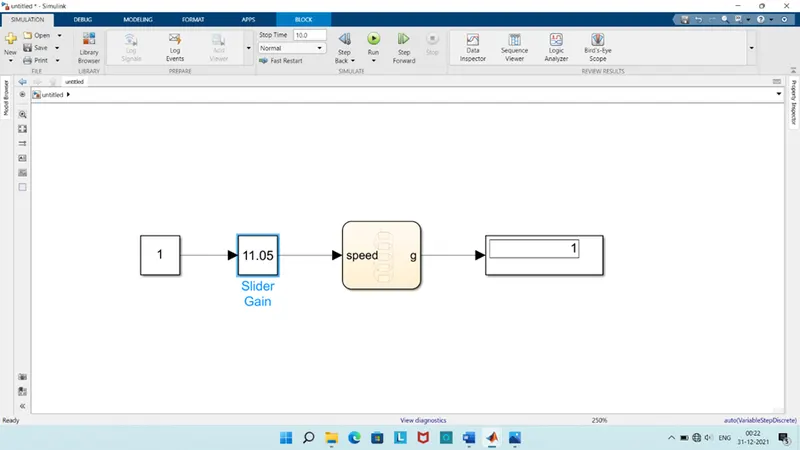
GEAR: 2
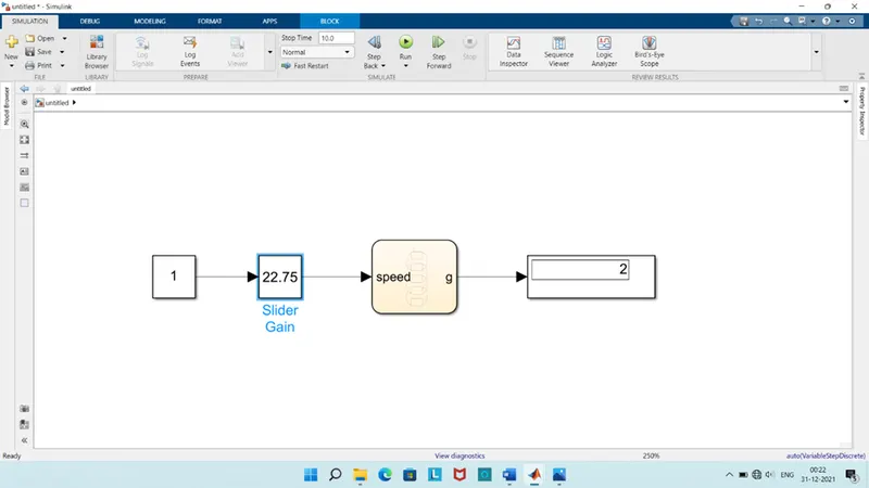
GEAR: 3
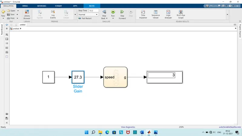
GEAR: 4
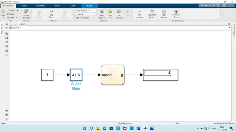
GEAR: 5