Week -2
OBJECTIVE:
Simulating a situation where the circuit switch is closed for 2 seconds and then released to observe physical movement of solenoid plunger hitting the doorbell.
Explanation:
The model shows a simple circuit that triggers a sound as doorbell at the completion of circuit.
It is modelled with constant voltage source.
Once the current flows through circuit and gets to solenoid, an electromagnetic field is created.
‘A’ is considered as an armature made of iron/nickel.
It has magnetic properties and turns into temporary magnet.
This attraction results in the armature striking the bell ‘B’ and making the sound.
SIMULINK MODEL EXPLANATION:
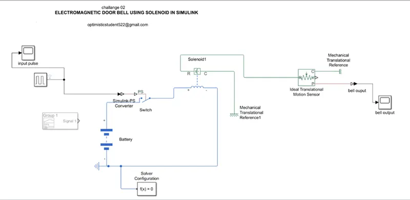
Pulse generator can be used to generate signal as per the need we able to modify input, but in this situation switch is operated for 2 seconds and then released.
The circuit represents model of electric bell. solenoid act as electromagnet in which mechanical partis wounded by coil to induce electric field.
MOTION SENSOR INPUT :
The input to the sensor unit is position which is to be sensed and so the initial length from bell to the hammer which strikes.
A pulse is generated, which gives instruction to switch that it must be closed for 2 seconds and then open.
Input pulse generator graph plot
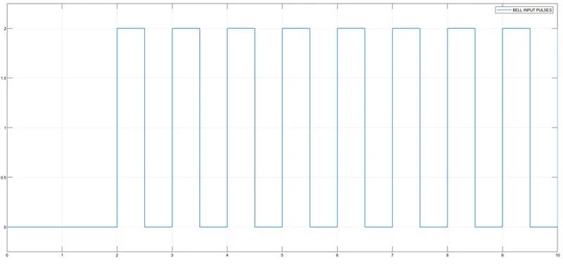
When switch is closed, current starts flowing in circuit and solenoid starts acting like electromagnet.
To see effect of solenoid on armature, a translational motion sensor is placed at output.
With a phase delay of 2 seconds, the pulse only starts sending signal to close the switch at 2 seconds.
These is evident vibration from striking, which damps out within second.
OUTPUT OF THE SOLENOID BELL
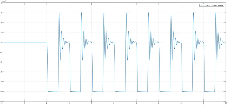
the output of the solenoid gives the case requirements of the hammer to strike the bell for the 2 seconds input signal which is showed.
OBJECTIVE:
MODELLING A THERMISTOR OPERATED AUTOMATIC FAN.
EXPLANATION:
A thermistor is a thermal resistor whose resistance vary on temperature.
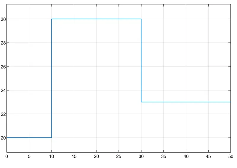
TEMPERATUR SOURCE
20*c --(0-10)s
27*c --(10-30)s
23*c--(30-50)s
Fan Conditions :
ON if the temperature is above 25*c
OFF otherwise.
A thermistor senses the temperature of a heat source and accordingly decides whether to send the signal to turn the fan or not.
A thermistor is a thermal resisitor whose resistance is dependent on the temperature it experiences.
NTC thermistor , whose resistance decreases with increase in temperature.
The thermistor base AUTOMATIC FAN CONTROL IS AN EXPERIMENT WHERE THE FAN IS TURNED ON ONLY IF THE TEMPERATURE EXPERIENCED BY THERMISTOR.
As the resistance of thermistor is decreased, it will use up lesser voltage provided by battery.
SIMULINK MODEL EXPLANATION:
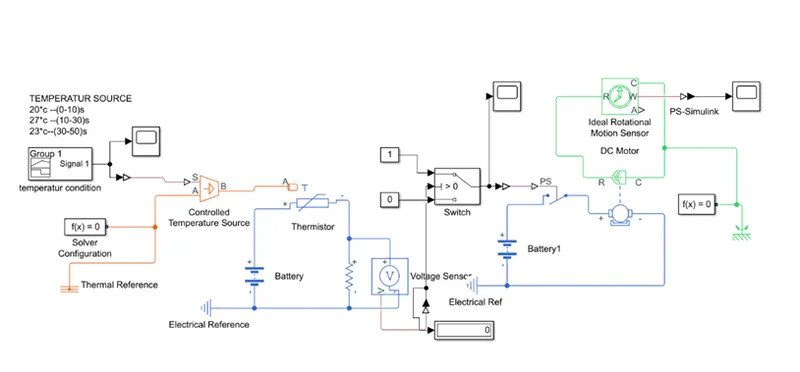
Signal builder is used for multiple temperatures, which was then find to the controlled temperature source,
The thermistor received those temperature as inputs and its resistance varied accordingly , which led to it using different amount of voltage every time the temperature was different.
A switch is used to meet this if condition threshold of the voltage, which then allows voltage to pass through dc motor.
The dc motor then powers the fan, and a rotational motion sensor is used to detect the outputs.
Since the Simulink is used to accept by the battery or the simscape switch so convert or is used to modify the data to the simscape and then its is connected to positive side of dc motor.
The motion sensor is used to detect the velocity and angular displacement by the motor the rotor part is connected to R.
Universal motor is to be damped with function as 1, otherwise the motor will be set in motion unless, damping or external force is applied on its as friction.
RESULT:
The result depicts that fan is turned on when it is above the temperature of 25*c with the input relevant data at the signal is 1, is 27*c turns off when temperature dips.