Week-6 Challenge: EV Drivetrain
Week-6 Challenge: EV Drivetrain
1)Type of power converter circuits employed in electric and hybrid vehicles.
A power converter is an electrical circuit that changes the electric energy from one form into the desired form optimized for the specific load. A converter may do one or more functions and give an output that differs from the input.
A pictorial representation of power converters in a hybrid vehicle is shown below.
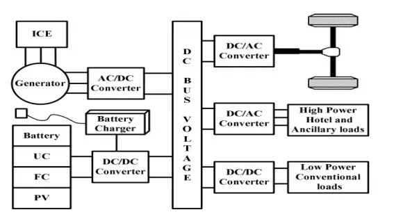
Power Converters used in Various Electrical application are shown below
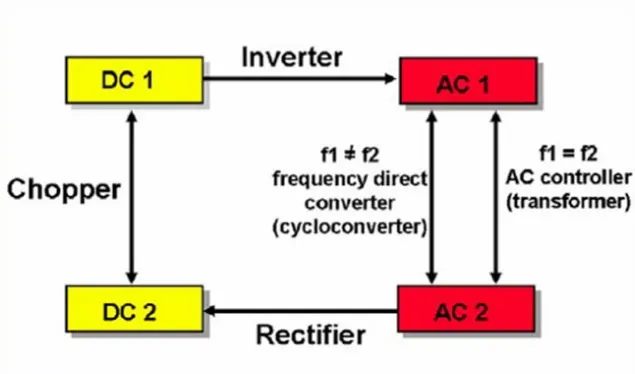
Power Converters used in EV and HEV are
- AC to DC Converter
- DC to DC Converter
- DC to AC Converter
a) AC to DC Converter: -
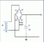
AC to DC Converter or Rectifier is the used to Convert alternating current by the generator or by the plug in supply to the form of Direct Current (DC) to store the charge in the rechargeable battery,
b) DC to DC Converter: -
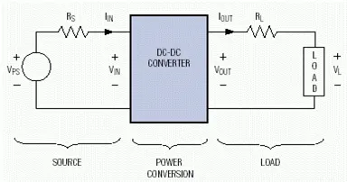
DC to DC converter or Chopper converter is used to convert stepdown the DC Voltage to the required level of voltage of 12V.In the Electric vehicle, it is used to covert electrical Voltage for low-power Conventional loads.
- b) DC to AC Converter: -
DC to AC Converter or Inverter converts direct current to the form of alternate current, it used to run high power Hotel and Ancillary loads from the DC voltage source in the electric vehicles.
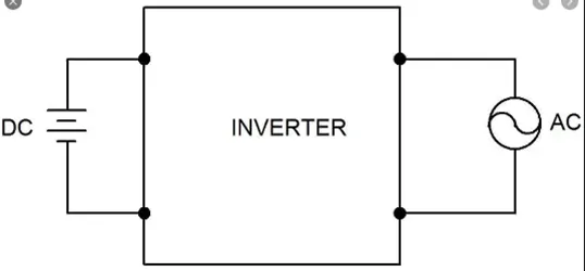
Note :- One more converter are there AC to AC type these types are not used in EV and HEV normally, AC to AC convert used to convert AC voltage with a same AC voltage with different Frequency or step up or step downed AC voltage with same frequency.
2)Given Data
Rated Armature Voltage =72V,
Rated Armature Current=400A,
Ra=0.5Ω,
KØ=0.7 Volt Second
Chopper switching frequency=400Hz.
Speed Torque Characteristic equation is
Tv=24.7+(0.0051)w2 -------(1)
Duty cycle Percentage =70%
Then V0=72*70/100
=50.4V
Tv=(Vo *KØ/Ra)-(w*KØ2/Ra)
Tv=50.4*0.7/0.5-w*0.72/0.5
Tv=70.56-0.98w -------(2)
To get the value of speed
Substituting value of Tv in equation (1)
70.56-0.98w=24.7+0.0051w2
0.0051w2+0.98w-45.86
It is in the form of ax2+bx+c
To get the value of x`=(-b±√(b^2-4ac))/2a`
Instead of x we have to find w here
`w=(-0.98±√(〖0.98〗^2-4*0.0051*(-45.86)))/(2*0.0051)`
w=38.91,w=-231.07
for the speed, only a positive value is considering so
w, speed =38.91
3)Mathematical model of a DC Motor for the equation w=V/ KØ-Ra/ KØ2.T
Simulink Blocks used
Constant: -This block is used twice in the Simulink model for a voltage source as 24v, and another for a kphi value the value of kphi kept as 0.65.
Product: - is used for multiplying the input given to the product block here product block is used for calculating the square value of kphi
Gain: -this block is used for multiplying with the gain value here torque value and Ra Value are given by using gain block
Divide: -This block is used for dividing the value of Voltage, V by kphi value .
Add: -This block is used for calculating the subtracted value of the input given
Display: - Used to display the output value (omega value)
Simulink model is shown below
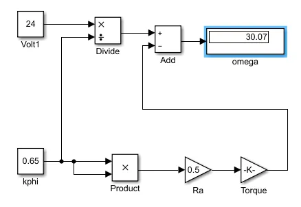
While giving v as 24v,kphi as 0.65,Ra value is 0.5 torque value is 32.422 then the value of omega is 30.07.
4.Induction versus DC Motor
Brushless DC Motor: -
The rotor includes two or more permanent magnets that generate a DC magnetic field. In turn, this magnetic field enters the stator core (a core made up of thin, stacked laminations) and interacts with currents flowing within the windings to produce a torque interaction between the rotor and stator. As the rotor rotates, it is necessary that the magnitude and polarity of the stator currents be continuously varied – and in just the right way - such that the torque remains constant and the conversion of electrical to mechanical energy is optimally efficient. The device that provides this current control is called an inverter. Without it, brushless motors are useless motors.
- Permanent magnets are expensive
- Permanent magnets are difficult to handle due to its very large force of attraction with ferromagnetic get in close to it
Induction motor
A forerunner of the 3-phase induction motor was invented by Nikola Tesla before 1889.The stators for the 3-phase induction motor and the DC brushless motor are virtually identical. Both have three sets of “distributed windings” that are inserted within the stator core. The essential difference between the two machines is with the rotor. Unlike DC brushless rotor, the induction rotor has no magnets – just stacked steel laminations with buried peripheral conductors that form a “shorted structure.” Currents flowing in the stator windings produce a rotating magnetic field that enters the rotor. In turn, the frequency of this magnetic field as “seen” by the rotor is equal to the difference between the applied electrical frequency and the rotational “frequency” of the rotor itself. Accordingly, an induced voltage exists across the shorted structure that is proportionate to this speed difference between the rotor and electrical frequency. In response to this voltage, currents are produced within the rotor conductors that are approximately proportionate to the voltage, hence the speed difference. Finally, these currents interact with the original magnetic field to produce forces – a component of which is the desired rotor torque. When a 3-phase induction motor is connected to utility type 3-phase power, torque is produced at the outset; the motor has the ability to start under load. No inverter is needed. The fact that induction motors are directly compatible with conventional utility power is the main reason for their success. In contrast, a brushless DC motor produces no starting torque when directly connected to fixed frequency utility power. They really need the aid of an inverter whose “phase” is maintained in step with the angular position of the rotor.
Limitations of 3 Phase induction motor
- Cannot operate from DC
- AC is mandatory to operate,
- Shaft speed is proportional to the line frequency
- Inverter is required to power an induction machine from battery or other dc source.
- To adjust speed inverter frequency, have to adjust
- Low torque performance while comparing with DC machines
- Feedback loops to be added and the inverter produces exact frequency that required for motor those induction motor is compatible with DC and DC brushless for vehicle application.
Both DC brushless and induction drives use motors having similar stators. Both drives use 3-phase modulating inverters. The only differences are the rotors and the inverter controls. And with digital controllers, the only control differences are with control code. (DC brushless drives require an absolute position sensor, while induction drives require only a speed sensor; these differences are relatively small.)
One of the main differences is that much less rotor heat is generated with the DC brushless drive. Rotor cooling is easier and peak point efficiency is generally higher for this drive. The DC brushless drive can also operate at unity power factor, whereas the best power factor for the induction drive is about 85 percent. This means that the peak point energy efficiency for a DC brushless drive will typically be a few percentage points higher than for an induction drive. In an ideal brushless drive, the strength of the magnetic field produced by the permanent magnets would be adjustable. When maximum torque is required, especially at low speeds, the magnetic field strength (B) should be maximum – so that inverter and motor currents are maintained at their lowest possible values. This minimizes the I² R (current² resistance) losses and thereby optimizes efficiency. Likewise, when torque levels are low, the B(magnetic field strength) field should be reduced such that eddy and hysteresis losses due to B(magnetic field strength )are also reduced. Ideally, B should be adjusted such that the sum of the eddy, hysteresis, and I² losses is minimized. Unfortunately, there is no easy way of changing B with permanent magnets. induction machines have no magnets and B fields are “adjustable,” since B is proportionate to V/f (voltage to frequency). This means that at light loads the inverter can reduce voltage such that magnetic losses are reduced and efficiency is maximized. Thus, the induction machine when operated with a smart inverter has an advantage over a DC brushless machine – magnetic and conduction losses can be traded such that efficiency is optimized. This advantage becomes increasingly important as performance is increased. With DC brushless, as machine size grows, the magnetic losses increase proportionately and part load efficiency drops. With induction, as machine size grows, losses do not necessarily grow. Thus, induction drives may be the favored approach where high-performance is desired; peak efficiency will be a little less than with DC brushless, but average efficiency may actually be better.
Conclusion: -As per the current research Induction motor is more compatible than of DC brushless motor for EV’s and HEV’s
Refernces