Week-6 Challenge: EV Drivetrain
AIM:
To Study about the type of power converter circuits and to find out the Steady State Speed for an electric vehicle’s powertrain.
OBJECTIVES:
- To find out which type of power converter circuits are employed in electric and hybrid electric vehicle.
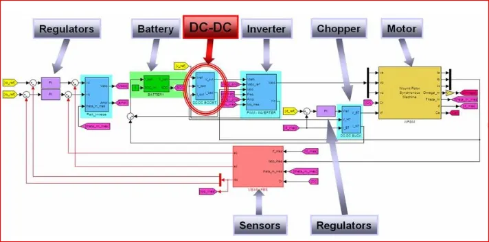
- An Electric vehicle’s Powertrain with 72V Battery pack in shown in the Diagram below. The duty ration for acceleration operation is “d1” and for the Braking operation the duty ration is “d2”.
The other Parameter of Electric Vehicle is given below:
Motor and Controller Parameter
Rated Armature Voltage = 72V
Rated Armature Current = 400A
Ra = 0.5 = 0.7 Volt second
Chopper Switching Frequency = 400Hz
3.Develop a mathematical model of a DC Motor for the below equation using Simulink.
`ω = V/K - R_a/K^2 × T_m`
4. Refer to the blog on below topic:
https://www.tesla.com/blog/induction-versus-dc-brushless-motors
Explain in brief about author’s perspective.
INTRODUCTION :
Which type of power converter circuit is employed in Electrical and Hybrid vehicle?
Power converters are electrical and electronic circuits that are used to either connect DC to AC and vice versa or to convert one level of DC voltage into another one (steps up or step down).
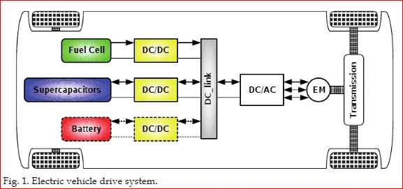
There are 4 different types of power converters but 3 power converters are employed in EV which are discussed below-
Power electronic converters are used everywhere in normal daily routines at home, commercial workplace or in an industrial environment.
Due to high power handling capacity with higher efficiencies, these converters have become integral part of industrial electrical drives, high electric power supplies, Electric traction systems and automobile control equipment.
There is different type of power electronic converters used to perform different function (for example- inversion, rectification etc.) which are rated from few mill watts to a few thousand watts.
- To find out which type of power converter circuits are employed in electric and hybrid electric vehicle.
EV / HEV Powertrain Basics-
The powertrain provides power to vehicle. It is refers to a set of component that generate required amount of power to move the vehicle.
The powertrain EV is way Simpler in construction than those vehicle associated with IC Engine.
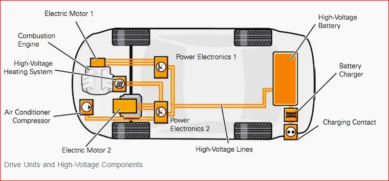
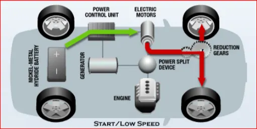
An IC Engine Vehicle has a greater number of moving and rotating of which Engine, Transmission , and Driveshaft are important. Power is generated by engine and transmitted to driveshaft and this consist major electrical components along with differentials, axles, emission controls, engine cooling system, exhaust and other parts.
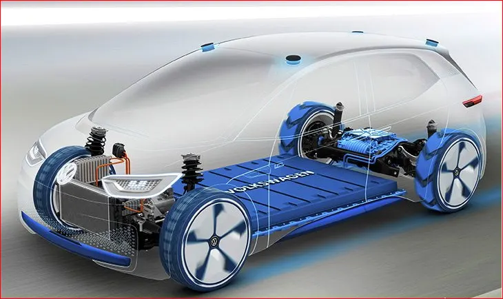
But EV power Drivetrain consist of less parts than ICE vehicle-
- Battery Pack –
This is made up of multiple lithium ion cells and stores the energy required to run the vehicle and provide direct current DC as output.
- DC –to- DC Converter –
A Battery pack delivers fixed voltage; but the requirement of the different auxiliaries in the EV would vary. The DC – DC converter helps to step down and distribute power to different systems.
- Battery Management System –
BMS continuously monitor the state of the Battery and is responsible for call balancing to deliver maximum efficiency from the battery.
- ON – Board Charger –
It converts AC supply received from the port to DC supply to charge back the battery pack.
- DC –to- AC Converter –
The DC supplied by the Battery pack is converted to AC to energize Electric motor. This power transfer is managed effectively by a motor.
- Controller –
It controls the frequency of the voltage with the help of power electronic modules which in turn controls the magnitude of the voltage in order to manage the speed of the motor as per the Acceleration of the Vehicle.
- Electric Motor –
This is the Prime of an EV unit which converts Electrical energy to Mechanical energy and Delivers to the Wheels via direct transmission or signal ratio transmission. This motor can act in regeneration modes.
- CAN Module –
This carries Communication between the control unit and the vehicle and motor.
POWER ELECTRONIC CONVERTER :
- The task of a power converter is to process and control the flow of electric energy by supplying voltage and current in a form that is optimally suited for the user loads. Energy was initially converted in electromechanical converters (mostly rotating machine). Today, with the development and the mass production of power semiconductors, static power converters find applications in numerous domains and especially in particle accelerators. They are smaller and lighter and their static and dynamic performance is better.
- Power electronic is the application of solid state electronic to the control and conversion of electric power.
- In modern systems, the conversion is performed with semiconductor switching device such as the power MOSFET & IGBT. In contrast the electronic system concerned with transmission and processing of Signal and Data, in power Electronic substantial amount of electrical energy is processed. The power range is typically from 10 watts to several 100 watts. In Industry the common application is Variable Speed Drive that is used to control the Induction motor. The power range of VSDs Starts from hundred watts and end at 10’s of Megawatts.
- Switching technique is adopted from power Electronic to control voltage and current for electric motor. This avoids high volume of losses by replacing resistor with power switch and these motor modules are operated with high frequency where the rated battery voltage ( ) can be reduced to desired voltage by ON –OFF of modules.
- Switching frequency will be in such a way that it utilizes and high and low switches to maintain average desired voltage.
- The principal behind Power modules isn’t controlling the magnitude of the Voltage but the duration of high and low value of a voltage resulting the desired voltage level.
- This ON –OFF frequency is termed as Dusty – ratio.
- Duty Ratio (D) =
- By changing the Duty Ratio of the Power Module, we can vary the voltage from one level to another level.
- According to the respective function performed, power electronic converters are categorized in the following types-
- AC to DC – Rectifier, it converts AC to Unipolar (DC) current.
- DC to AC - Inverter, it converts DC to AC of desired frequency and voltage.
- DC to DC – Chopper, it converts constant to variable DC or variable DC to Constant DC.
- AC to AC - Cycloconverter, Matrix converter-it converts AC of desired frequency or desired voltage magnitude from AC supply.
- These power Electronic converter may be found in wide variety of application such as Switch mode power supplies (SMPS), Electric machine control, Energy storage system, Lightning Drive, Power generation & distribution, Active power filters, Renewable energy conversion, flexible energy transmission let us go in detail about each converter.
AC to DC converter/ (Rectifiers)-
This power electronic converter Converts AC supply from main line to DC supply or the Load. The Block diagram of this converter is shown below-
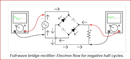
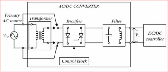
The Essential components of the rectifier includes Transformer, Control block, Filter, Switching Unit.
Transformer adjusts the primary AC source supply to the input of Rectifier stage. Usually it is step down transformer that reduced the supply voltage to a circuit operating range.
The rectifier converts the Low voltage AC supply into DC supply. It consist of Diode / Thyristors based on type of rectifier, the output of the rectifier is of pulsed DC and hence it is filtered using filter circuit, which is usually made with a capacitor or a choke.
The control block controls the firing angle of Thyristors in case of phased controlled rectifiers. Since Diode is not controllable device, control block is not needed in case of Diode rectifiers.
Rectifier are divided into 2 types –
- Uncontrolled Diode Rectifiers.
- Controlled Rectifiers.
DC to AC Converter (Inverter) –
These converters are connected between DC source of fixed input and variable AC load. Most commonly these DC to AC converters are called Inverters.
An inverter is a static device that converts fixed DC supply voltage to variable AC supply voltage.
Fixed DC voltage is obtained from Batteries or by DC link in most power electronic converters. The output of the inverter can be variable or Fixed AC voltage with variable or fixed frequency.
This conversion from DC to AC along with the variable supply is produced varying the triggering angle of Thyristors. Most of the Thyristors are used in inverters are employed with forced communication technique.
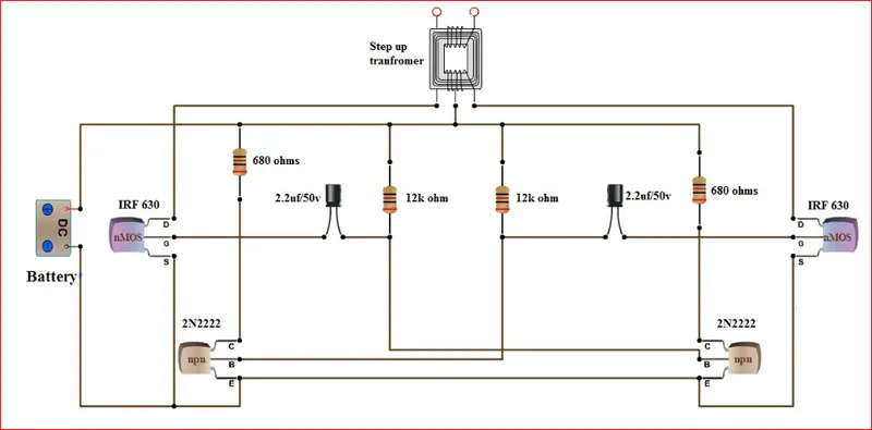
This can be single phase or three phase inverter depending upon the supply voltage. These converters are mainly divided into 2 groups.
- PWM based inverters.
- Multilevel inverters.
Further these are classified voltage source inverters and current source inverter. Each type is subdivided into different type of PWM, SVPWM etc.
Multilevel inverters are most popular in industrial applications.
Refer lec Link:https://skill-lync.com/workshop/power-electronics-introduction-to-dc-ac-power-inverters
DC to DC Converter –
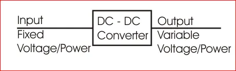
Many DC operated application need different levels of DC voltage from a fixed DC source.
Some of these applications include subway cars, DC traction systems, control of large DC motors, Battery operated vehicle, large buses etc. which require variable DC to produce variable speed, so a power conversion device is needed.
A DC chopper is a static device that converts a fixed input DC voltage to variable DC output of different magnitude (which can be lower or higher) than input value.
The chopper circuit is connected between DC input source and DC load. The chopper consist of power Electronic switching device such as pulse with modulation (PWM) control.
DC choppers are mainly used in DC drive i.e. EVs and HEVs.
DC chopper are classified into three basic types based on input and output voltage level and are discussed below-
STEP UP CHOPPER OR BOOST UP CONVERTER –
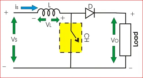
In this chopper the output voltage is always greater than input voltage and a switch is also used connected in parallel with the load and the switch is thyristor or a SCR.
A Diode is placed in series with the load that allows load current to flow when the thyristor is turned OFF.
When Thyristor is turned ON, the diode is reversing biased and hence it isolates the load circuit from the source. So the inductor charges to the maximum input voltage source.
When Thyristor is turned OFF, the load gets the voltage from the inputs as well as from inductor. So the voltage appearing across the converter output will be more that the input.
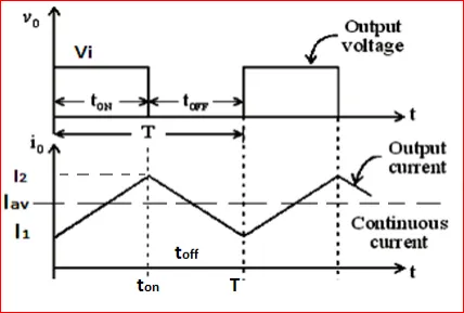
STEP DOWN CHOPPER OR BUCK CONVERTER –

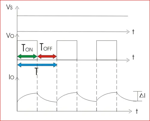
A step down chopper produces an average output voltage lower than input DC voltage. Here the Switching component is a thyristor that switches the input voltage to the load when it is triggers at particular instant.
A diode acts as a freewheeling diode that allows the load current flow through it when thyristor is turned OFF. If diode is absent, a high induced EMF in inductance may cause damage to the switching device.
The average output voltage of the converter is varied by controlling turn ON /OFF periods of Thyristor. When thyristor is turned ON, the output voltage is same as input voltage and if Turn OFF, the output voltage is zero. And the output voltage is equal to (TON / T) Vin. So by controlling Duty ratio K = (TON / T), the output voltage will be increased.
FLYBACK CONVERTER –
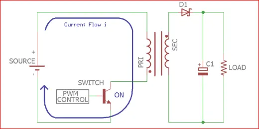
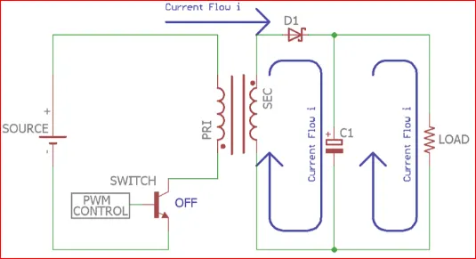
The flyback converter is used in both AC to DC and DC to DC conversion with galvanic isolation between the input and output. The flyback converter is a buck-boost converter with the inductor split to form a transformer, so that the voltage ratio are multiplied with an additional advantage of isolation for example a driving lamp or a voltage multiplier the rectifying diode of the boost converter is left out and the device is called a flyback transformer.
AC TO AC CONVERTER -
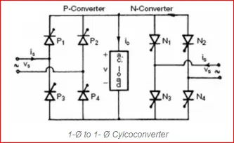
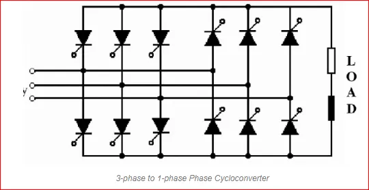
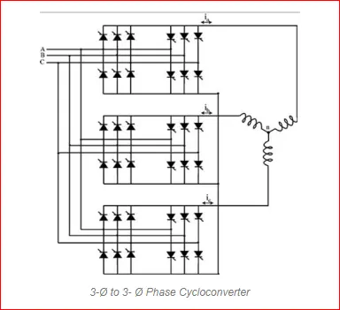
Thes types of power eletronic converters are used to convert alternating current waveforms of specific magnitude and specific frequency into alternating current waveform with different magnitude and different frequency, as the signal remain AC and hence this is termed as Ac to Ac converter.
to operate few device and machine we required some specific voltage with specific frequency that can be obtained wit AC -AC converter and by regulating AC power using AC - AC converter we can regulate the speed of induction motors.
2.An Electric vehicle’s Powertrain with 72V Battery pack in shown in the Diagram below. The duty ration for acceleration operation is “d1” and for the Braking operation the duty ration is “d2”.
The other Parameter of Electric Vehicle is given below:
To FIND STEADY-STATE SPEED IF DUTY CYCLE IS 70%
Motor and Controller Parameter
Rated Armature Voltage = 72V
Rated Armature Current = 400A
Ra = 0.5 `Ω`
`K∅` = 0.7 Volt second
Chopper Switching Frequency = 400Hz
The vehicle characteristics are given by the equation
`T_v =24.7-0.0051 ω^2`
What is EV steady state speed if the duty cycle is 70 % ?
As given ,
Battery pack in EV Drivetrain = 72 v(armature voltage)
Armature current = 400 A
Armature Resistance Ra = 0.5 Ω
Motor constant = 0.7 V-s
Chopper Switching frequency = 400 Hz
For the value of “V” i.e Average Voltage we need multiply the Armature Voltage with Duty Cycle,
Speed-Torque Equation of Motor,
`ω = V/K - R_a/K^2 × T_m`
Where,
`T_m`= Torque
V = Voltage
N (ω) = Motor Speed
Ra = Armature Resistance
K = Motor Constant (Armature control motor)
The Derived formula for motor speed characteristics is,
`T_m = V/R_a .K- K^2/R_a ×ω` …………………..(1)
After substituting the input value in eq (1)we get
`T_m = (50.4 ×0.7 )/0.5 – 〖0.7〗^2/0.5 ×ω`
`T_m =70.56-0.98 ω^2` …………………….(2)
We have been given that vehicle speed torque characteristics as,
`T_v =24.7-0.0051 ω^2` …………………..(3)
At Steady state ,
`T_v= T_m` …………………..(4)
Substituting Eq no. 2 and Eq no. 3 in Eq no. 4 we get,
`T_v= T_m`
`24.7-0.0051 ω^2 = 70.56-0.98 ω^2`
`0.0051 ω^2+ 0.98ω-45.85 =0`
We now use the QUADRATIC EQUATION FORMULA to solve the above Equation,
`0.0051 ω^2+ 0.98ω-45.85 =0` comparing it with `〖ax〗^2+bx+c=0`
Where ,
a = 0.0051 b = 0.98 c = 45.85
For solving the QUADRATIC EQUATION , we have to use below formula,
`x=ω`
`x= (- b ± √(b^2- 4ac))/2a`
`x= (- 0.98 ± √(〖(0.98)〗^2- 4(0.0051)(-45.85)))/(2.(0.0051))`
ω = 38.92 rad/sec
- Develop a mathematical model of a DC Motor for the below equation using Simulink.
INPUT_Script MATLAB: https://drive.google.com/file/d/1V4DZXvyqUxbBb18ctoDEDgOjtLFKyHMF/view?usp=sharing
clear all
close all
clc

% Torque Speed Characteristics of DC Machine.
% Array of motor speed in rad/sec
Speed  = linspace(0,500,50);

% Input of Speed constant of a motor  (rpm/v)
N_s   =  input('Enter the value of Speed Constant of Motor = ');

% Input the Battery voltage supply value.(volts)
V   =  input('Enter the value of Voltage Supply = ');

%Input the Armature Resistance. (ohms)
R_a  =  input('Enter the value of Armature Resistance = ');

% Back E.M.F developed
EMF  =  1 ;  % back emf is directly proportional to speed constant given in the dat is per unit voltage

%Calculating the constant of proportionality in emf and speed relation
k_phi  =  (EMF*60)/(N_s*2*3.14);

% the DC motor Speed torque charateristics
% T = ((V*k_phi/R_a) - ((k_phi)^2/R_a)*omega)
% Calculation of Torque
 T  =  ((V*k_phi/R_a) - (((k_phi)^2/R_a).*Speed));


 % To calculate Total Current in Ampere
 TC  =  (V - EMF)/R_a;

 % To Calculate the maximum Torque
 T_max  = k_phi*TC ;


  %Convert Speed value in rpm from rad/sec
 Speed  =  Speed*60/(2*3.14);

 % Plotting the D.C.Machine charateristics w.r.t Speed Vs Torque
 plot(Speed,T,'color','r','linewidth',3);
 xlabel('Speed (RPM)');
 ylabel('Torque (Nm)');
 title('D.C.Machine Charateristics wrt Speed Vs Torque');
SIMULINK MODEL: https://drive.google.com/file/d/1njjOgaDypshZBI4uydUKiGgzFV592qEJ/view?usp=sharing
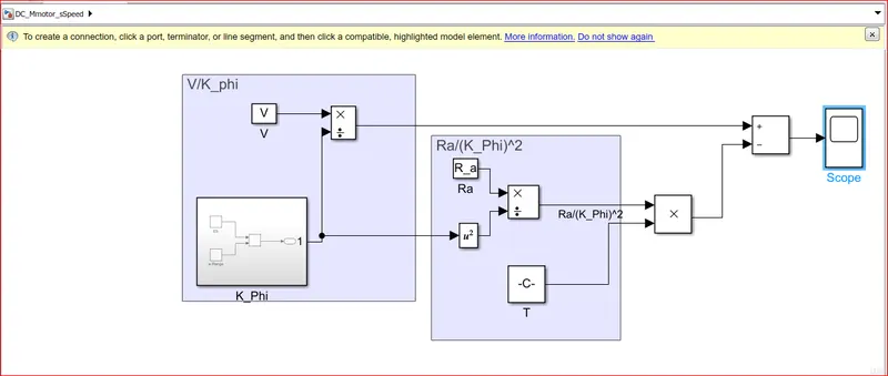
SUBSYSTEM:
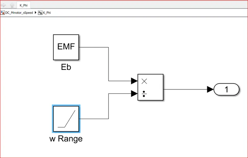
RESULTS:
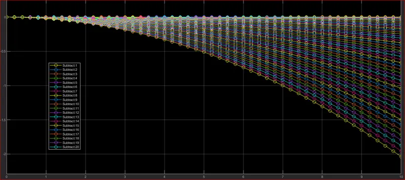
EXPLANATION:
- The speed is determined with a help of mathematical model in simulink, By preparing the model which governs the above Speed formula.
- New model in Simulink is opened and saved with name DC_Mmotor_sSpeed,then in that model we take constant block it’s input is “V“ from the workspace.
- “K” is Eb/speed so we take “Eb” in constant block and it’s input as ”EMF” from the workspace.
- Further we take divide block and connect multiplication port to EB as it is directly proportional and divide port to Speed from workspace, and create a Subset of it with asking for output port block.
- In Similar way Subset is created for Ra/K^2*T as shown in Model diagram.
4. Refer to the blog on below topic:
https://www.tesla.com/blog/induction-versus-dc-brushless-motors
Explain in brief about author’s perspective.
According to the blog “Induction versus DC Brushless motor by Wally Rippel, Tesla”, the author wants to highlight topics related to EV technology, especially related to DC brushes and motors.
According to him, DC is replaced by DC Brushless motors or Induction motors. Also, Lead-acid Battery is replaced by lithium ion batteries for EV’s. he said that there will be the future of both the components induction and brushless DC motor depends upon their demands and uses.
DC Brushless Motor:
The technology behind the DC Brushless motor is that it has more than 2 permanent magnet which generates a DC magnetic field. For better Torque generation in rotor and stator, a current flow in winding and this happen due to magnetic field near the stator. According to him, the brushless motor needs a proper flow of current into rotor and stator if it will be not in proper way then the current will not generate and there will be decrease in torque. To maintain electrical to mechanical conversion there should be smooth flow of current otherwise the brushless motor is not useful. A brushless motor does not create any starting torque.
The advantage of DC Brushless motor is that there is low heat generation in the rotor, its cooling capacity is better as compared to induction motor drive; Also Peak Power efficiency is high. Another difference is that DC Brushless drive can also operate at unity power factor, whereas the best induction drives is about 85%, this means that the peak point energy efficiency for a DC Brushless drive will typically be a Few % points higher than for an Induction drive.
INDUCTION MOTOR:
The technology behind the induction motor is that it basically uses a 3-phase Induction motor which was Discover by “Nikola Tesla” in 1889. In Induction motor there is the use of steel laminated device instead of Magnets. Currents flowing in the stator windings produce a rotating magnetic field that enters the rotor. In an Induction motor current interacts with the Magnetic field generated by stator to produce a force which is required for rotor torque. The induction motor is compatible with a power source. An induction motor cannot operate from DC voltage it always require AC voltage.
The induction motor does not have any magnets and in this the B field is adjustable. In an induction motor B field is proportionate to V/f (Voltage to frequency). This technology is used to reduce the magnetic losses and conduction losses, due to which efficiency will maintain at maximum peak. This all lead to increase the performance, induction motor is very useful and efficient for high performance. In an induction motor, the peak efficiency is less but it works smoothly better. The controlling of induction motor or mechanism is more complex. Also the Torque generated is low and the motor temperature increases when it works at high speed.
Inference:
Now, the question is that which one is the best brushless DC motor or Induction motor, then during 1990s General Motor EV-1 and Tesla Roadster work by using induction motors and rest all HEV were using DC Brushless motors. Both the drives means DC and Induction motor using 3-phase modulating inverters. The only difference is in rotor and inverter controller of the motors.
According to Sensors, the DC Brushless motor requires absolute position sensor whereas induction motor only needs speed sensors.
Another factor is related to cost of permanent magnets it is costly in Kg. Also, the permanent magnet rotor needs more careful maintenance and it’s difficult to handle. So the cost of induction motor is less.
The conclusion according to the author is that the induction motor drives is only best for Pure High Performance EV whereas, DC Brushless drive are beneficial for all hybrid as well as Plug-In Hybrid Vehicle.
CONCLUSION:
- We have discussed about the different types of power converter circuit employed in electric and hybrid electric vehicles.
- The EV steady state Speed of an EV Drivetrain was determined with the given inputs conditions.
- We have studied a Blog on the Topic “Induction motor Vs DC Brushless motor by
Wally Rippel” , “Nikola Tesla” and explained about the author’s perspective.-
UPLOADED SOURCE LINK:
https://drive.google.com/drive/folders/1nGO6iZKbmotC3HJclgMBDoUA4GNIcDvd?usp=sharing
NOTES:
https://drive.google.com/file/d/1ot5-h4O2sV7d8dYb4glVXE9c0pmYQda9/view?usp=sharing
REFERENCE:
1. http://tijarohonline.blogspot.com/2011/02/basic-rectifier-circuit.html
2.https://www.electronicshub.org/12v-dc-220v-ac-converter-circuit/
3.https://www.electrical4u.com/chopper-dc-to-dc-converter/
4.https://www.elprocus.com/what-is-a-flyback-converter-design-its-working/
5.https://circuitdigest.com/electronic-circuits/flyback-converter-circuit-diagram
8.https://matlabhelper.com/blog/simulink/electric-vehicle-simulation-in-simulink/
9. https://www.elprocus.com/ac-to-ac-converter-working-and-supplies/