Power Electronics in EV Drivetrain
Aim- Power Electronics in EV Drivetrain
Objectives-
- To understand about the power converter circuits in electric and hybrid electric vehicle.
- To calculate the speed of the vehicle by making use of the duty ratio.
- To understand about Induction and DC brushless motors.
Power Converter Circuits-
The conversion of power from one form to another and the change from one voltage level to another level by using power converter circuits is generally termed as power electronics.
Power converters are made of solid-state devices which act as switches, such as bipolar junction transistor (BJT), metal oxide semiconductor field effect transistor (MOSFET), insulated gate bipolar transistor (IGBT), thyristors.
We have the following types of converters used in EV/HEVs-
- DC to DC
- AC to DC
- DC to AC
DC to DC converter (Chopper)-
It is power electronic device that converts fixed DC into variable DC directly. A chopper is a high speed switch which connects and disconnects the load from source at a high rate to get a variable voltage at output.
Choppers are further classified into three types-
- Step-down Chopper or Buck converter- A step-down chopper produces an average output voltage lower than the input DC voltage.
- Step-up Chopper or Boost converter- produces the output voltage is greater than input voltage.
- Buck/Boost converter-it can be used both in step-down and step-up modes by continuously adjusting its duty cycle.
Application in EV/HEV- It is mostly used for powering auxiliary loads like headlights, speakers, infotainment system, sensors, safety equipment, regenerative braking etc.
DC to AC converter (Inverter)-
An inverter is a power electronic device that converts DC power to AC power for powering an electric vehicle motor. It can change the power or torque of the motor by adjusting the amplitude and can also change the torque/power by altering the frequency.
AC to DC converter (Rectifier)-
A rectifier is a power electronic circuit that convert input AC voltage to DC. It is generally used for charging purposes in an EV/HEV.
EV Drivetrain Calculations-
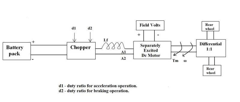
Specifications-
Motor and Controller Parameters:
- Rated Armature voltage = 72 V
- Rated armature current = 400 A
- Ra= 0.5Ω
- KΦ= 0.7 Volt second
- Chopper Switching frequency= 400 Hz
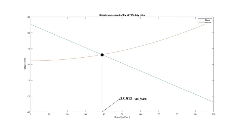
Vehicle’s speed-torque characteristics is-

`"Duty cycle"=70%=0.7`
thus,
`"Actual voltage"=0.7" x ""rated armature voltage "`
`"Actual voltage"=0.7" x "72 =50.4 " V"`
Speed-torque characteristics for a DC motor is given as-
`T=(Vkphi)/R_a-((kphi)^2/R_a)w`
`T=(50.4"x"0.7)/0.5-((0.7)^2/0.5)w`
`T=70.56-0.98w`
therefore,
`24.7+(0.0051)w^2=70.56-0.98w`
`(0.0051)w^2+0.98w-45.86=0`
`w^2+192.156w-8992.156=0`
`w= 38.915 or-231.07158 " rad/s"`
neglecting the neagtive solution
`"Speed of EV"(w)=38.915 " rad/s"`
MATLAB SCRIPT-
clear all                               % Clears command history
close all                               % Closes  all windows
clc                                     % Clears command window

%% motor and controller parameters
vol_arm=72;                             %rated armature voltage
curr_arm=72;                            %rated armature current
Ra=0.5;                                 %armature resistance
k_phi=0.7;                              %motor constant
d=0.7;                                  %duty cycle
vol_ac=vol_arm*d;                       %actual voltage
w=0:0.01:100;                           %angular velocity
% vehicle's speed torque characteristics
Tv=24.7+0.0051.*w.^2;
% motor's speed torque characteristics
Tm=(vol_ac.*k_phi)/Ra-((k_phi).^2/Ra).*w;

%% plotting
plot(w,Tm)
hold on
plot(w,Tv)
xlabel("Speed(rad/sec)")
ylabel("Torque(Nm)")
title('Steady state speed of EV at 70% duty ratio')
legend('Motor','Vehicle')
Induction vs DC brushless motors-
The blog by Wally Rippel mainly focuses on the induction and DC brushless motors. The author lists out various comparisons between these two types of motors based on performance, control strategy, torque generation, rotor cooling and production costs.
According to Wally Rippel the following comparisons can be made-
|
DC brushless motor |
Induction motor |
|
|
Rotor construction |
Permanent magnets |
Steel laminations |
|
Stator construction |
Distributed winding inside stator core |
Distributed winding inside stator core |
|
Supply voltage type |
DC |
AC 3 phase |
|
Control strategy |
Inverter needed to vary currents |
Can run on 3 phase AC directly |
|
Speed |
Can be varied by inverter |
Can run at constant speed |
|
Cooling |
Heating is lower and can be cooled easily |
Heating is more due to formation of eddy currents |
|
Efficiency |
High |
Low |
|
Magnetic losses |
Increases with size of motor |
Doesn’t increase with size |
|
Cost |
Expensive |
Cheaper |
The author concludes that there is no such motor to prefer over another. It all depends on the requirements. He states that DC brushless motors are better for hybrid electric vehicles and Induction motors are better suitable for high performance pure EVs. He wishes to see both drives work together in the future.
References-
- “4-Different Power Converters.” Electronics Hub, 25 Dec. 2017, www.electronicshub.org/4-different-power-electronic-converters/.
- “How Electric Vehicles Work.” Sustainable Energy Authority Of Ireland, www.seai.ie/technologies/electric-vehicles/what-is-an-electric-vehicle/how-electric-vehicles-work/#:~:text=An%20inverter%20is%20a%20device,frequency%20of%20the%20alternating%20current