Study on Electric Vehicle Drivetrain
Week 6 Challenge: EV Drivetrain
AIM:
(1) Explain the types of power converter circuits used in electric and hybrid electric vehicles.
(2) Calculate the steady-state speed of an Electric Vehicle's powertrain with a 72V battery pack when the duty cycle is 70%.
(3) Comment on the author’s perspective on the topic of Induction Motor vs DC Brushless motor.
SOLUTIONS:
(1) Explain the types of power converter circuits used in electric and hybrid electric vehicles.
Answer:-
The task of a power converter is to process and control the flow of electric energy by supplying voltages and currents in a form that is optimally suited for the user loads. It is used for power conditioning in traditional rectifier circuits for high power requirements, but also today virtually all types of electronic devices use power electronics in some fashion.
Power electronic converters perform various basic power conversion functions. This converter is a single power conversion stage that can perform any of the functions in AC and DC power conversion systems.
Depending on the type of function performed, power electronic converters are categorized into the following types.
- AC to DC = Rectifier: It converts AC to unipolar (DC) current
- DC to AC = Inverter: It converts DC to AC of desired frequency and voltage
- DC to DC = Chopper: It converts constant to variable DC or variable DC to constant DC
- AC to AC = Cycloconverter, Matrix converter: It converts AC of the desired frequency and/or desired voltage magnitude from a line AC supply.
(I) AC-DC converter:
An AC to DC converter is also called a rectifier, which converts AC supply from main lines to DC supply for the load. The rectifier converts the low voltage AC supply into DC supply.
It comprises a diode and/or thyristors based on the type of rectifier. The output of the rectifier is of pulsed DC and hence it is filtered using a filter circuit, which is usually made with a capacitor or a choke. The control block controls the firing angle of thyristors in case of phase-controlled rectifiers. Since the diode is not a controllable device, a control block is not needed in case of a diode rectifier. Chargers are the best example for AC-DC converters.
(II) DC-AC converter:
A DC-AC converter is a device that converts DC power from the battery to AC power used in an electric vehicle motor. This can change the speed at which the motor rotates by adjusting the frequency of the alternating current. They are called as inverters.
The use of this converters can increase or decrease the power or torque of the motor by adjusting the amplitude of the signal. It plays a significant role in capturing energy from regenerative braking and feeding it back to the battery.
The key component is that it has a direct impact on on-road performance, driving range and reliability of the vehicle also as a consequence of their weight and size. The output voltage waveform of an ideal inverters should be sinusoidal. However, the waveform of practical inverters are non-sinusoidal and contain certain harmonics.
(III) DC-DC converter:
In the configurations of EV power supply, at least one DC/DC converter is necessary to interface the Fuel Cell, the Battery or the Supercapacitors module to the DC-link. They are also known as a chopper.
In electric engineering, a DC to DC converter is a category of power converters and it is an electric circuit which converts a source of direct current (DC) from one voltage level to another, by storing the input energy temporarily and then releasing that energy to the output at a different voltage. The storage may be in either magnetic field storage components (inductors, transformers) or electric field storage components (capacitors).
DC/DC converters can be designed to transfer power in only one direction, from the input to the output. However, almost all DC/DC converter topologies can be made bi-directional. A bi-directional converter can move power in either direction, which is useful in applications requiring regenerative braking. In the case of interfacing the Fuel Cell, the DC/DC converter is used to boost the Fuel Cell voltage and to regulate the DC-link voltage. However, a reversible DC/DC converter is needed to interface the SCs module. However, some design considerations are essential for automotive applications:
-
Lightweight,
-
High efficiency,
-
Small volume,
-
Low electromagnetic interference,
-
Low current ripple drew from the Fuel Cell or the battery,
-
The step-up function of the converter,
-
Control of the DC/DC converter power flow subject to the wide voltage variation on the converter input.
(IV) AC-AC converter:
AC to AC converters connect an AC source to AC loads by controlling the amount of power supplied to the load. This converter converts the AC voltage at one level to the other by varying its magnitude as well as the frequency of the supply voltage.
These are used in different types of applications including uninterrupted power supplies, high power AC to AC transmission, adjustable speed drives, renewable energy conversion systems and aircraft converter systems.
-------------------------------------------------------------------------------------------------------------------------------------------------------------------------------------------------------------------------------------------------
(2) Calculate the steady-state speed of an EV if the duty cycle is 70% with the given conditions.
Given:-
An Electric Vehicle's powertrain with 72V battery pack in shown in the diagram below. The duty ratio for acceleration operation is 'd1' and for the braking operation the duty ratio is 'd2'.
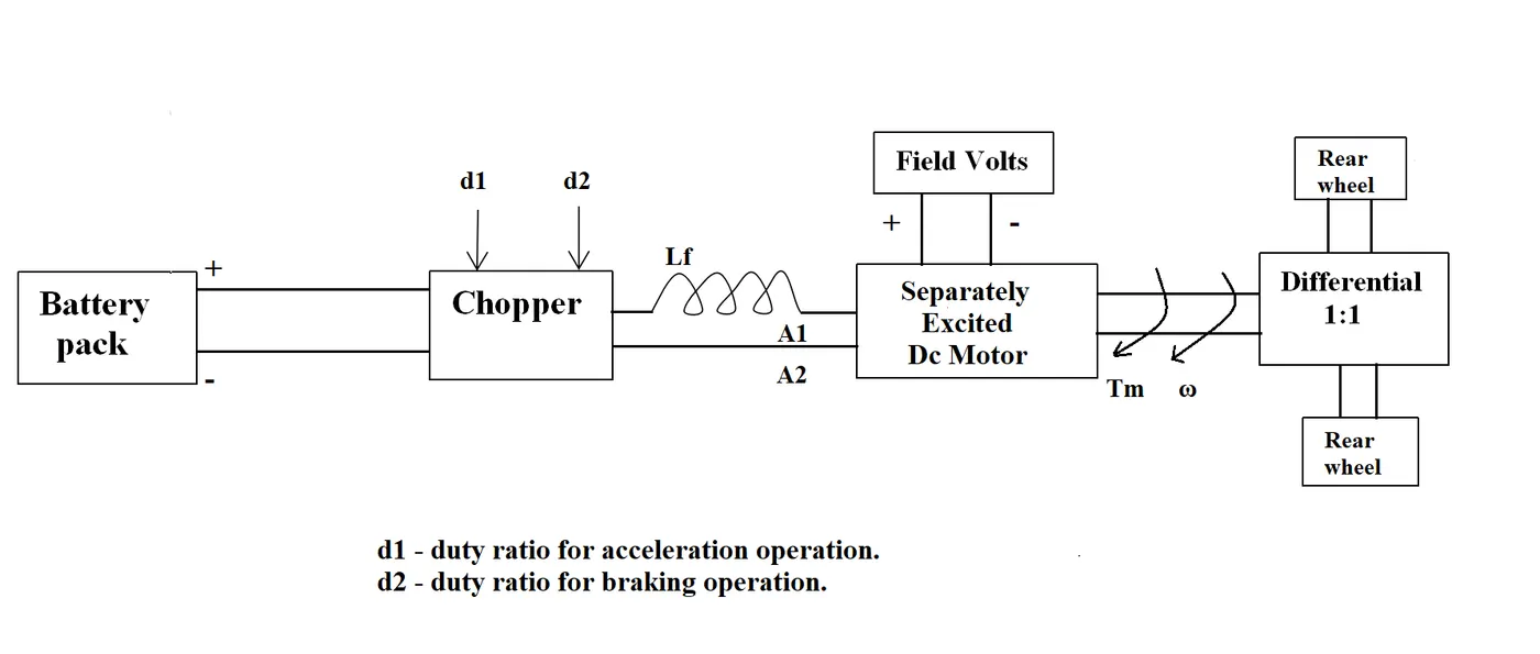
The other parameters of the electric vehicle are given below,
Motor and Controller Parameters:
- Rated Armature voltage= 72 V,
- Rated armature current= 400 A,
- Ra= 0.5Ω,
- KΦ= 0.7 Volt second and
- Chopper Switching frequency= 400 Hz
Answer:-
We have,
`V_a = 72V`
`I_a = 400A`
`R_a = 0.5 ohms`
`kphi = 0.7 V-sec`
`f = 400 Hz`
By ohm's law, we know that,
`V = T*R`
but `V = V_s - E_b`
`therefore I = (V_s-E_b)/R_a`
`I = V_s/R_a - E_b/R_a`
`=V_s/R_a - (Kphiomega)/R_a`
and we also know that `T prop KphiI`
`therefore T= (kphiV_s)/R_a - ((kphi)^2)/R_a*omega`
We have calculated for 70% duty cycle with the steady-state condition
`V_s = V_a`
`V_s = 72 * 0.7 = 50.4V`
So putting the values in the above equation;
`T = (0.7*50.4)/0.5 - (0.7)^2/0.5*omega`
`therefore T = 70.56 -0.98omega` -----eqn (i)
The vehicle speed-torque characteristics are given by the below equation
`T_v = 24.7+(0.0051)omega^2` -----eqn (ii)
Comparing equation (i) and (ii);
`70.56 - 0.98omega = 24.7 + 0.0051omega^2`
`0.0051omega^2 + 0.98omega - 45.86 = 0`
Solving the quadratic equation,
| `omega = 38.16 (rad)/sec` |
The steady state speed of an EV at 70% duty cycle is 38.16 rad/sec.
-------------------------------------------------------------------------------------------------------------------------------------------------------------------------------------------------------------------------------------------------
(3) Comment on the author’s perspective on the topic of Induction Motor vs DC Brushless motor.
Answer:-
This blog is written by Wallry Rippel and it is published on the TESLA's official website. He is a long-time proponent of electric vehicles. Prior to joining Tesla Motors, he was an engineer at AeroVironment, where he helped develop the EV1 for General Motors and was featured in the documentary movie, Who Killed the Electric Car? Wally has also worked for the Jet Propulsion Laboratory on electric vehicle battery research, among other projects. In 1968, as a Caltech undergraduate student, he built an electric car (a converted 1958 Volkswagen microbus) and won the Great Transcontinental Electric Car Race against MIT. The following are the observation from the blog.
- In the blog of induction and DC brushless motor, the author has mentioned about positives and negative side of both the induction and DC motor. and the basic construction of both the induction and DC brushless motor is explained.
- In the case of DC brushless motor, permanent magnets are used which produces a rotating magnetic field. This magnetic field when induces a current in the conductor. This current results in force generation in the rotor and this results in rotation of the rotor.
- Whereas in case of induction motor, the current is supplied to the stator which results in the generation of emf, when this emf comes in contact with the rotor which is generally a squirrel cage type, this results in current induced in the rotor. Unlike the DC motor, the rotor consists of conductors plates and placed in a cage-like structure. This also consists of bars around them in which currently get induced and the rotor starts rotating.
- One of the main differences is that much less rotor heat is generated with the DC brushless drive. Rotor cooling is easier and peak point efficiency is generally higher for this drive. It is mentioned that the DC brushless can drive at unit power factor, whereas the best power factor for the induction drive is about 85%.
- In the case of DC brushless motor, the strength of the magnetic field is adjustable. When at low speed the maximum torque is required magnetic field should be maximum, i.e. inverter and motor current maintained at their lowest optimize efficiency. Whereas there is no such adjustment in case of induction motor.
- As machine size grows, magnetic losses increase proportionally and part load efficiency drops. In case of induction motor, as machine size grows, losses do not necessarily grow.
- The construction of the DC brushless motor is costly compared with an induction motor, due to the use of permanent magnets.
- However thought the speed variation of an induction motor depends upon the frequency input, it is difficult to control.
------------------------------------------------------------------------------------------------------------------------------------------------------------------------------------------------------------------------------------------------
CONCLUSION:
- Studied the different types of power converter circuits employed in an electric and hybrid electric vehicle.
- The power electronic components play a very important role in the vehicle control and operation of the vehicle.
- BLDC and Induction motor drives will prevail in the market in the years to likely maintain dominance for the high-performance of the different types & combination of Electric vehicles.
REFERENCE:
- https://cds.cern.ch/record/987498/files/p13.pdf
- https://www.electronicshub.org/4-different-power-electronic-converters/
- https://www.intechopen.com/books/electric-vehicles-modelling-and-simulations/dc-dc-converters-for-electric-vehicles#:~:text=There%20are%20five%20main%20types,used%20for%20voltage%20step%2Dup.
- https://skill-lync.freshdesk.com/support/solutions/articles/43000574900-power-converters-in-ev-hev
- https://www.tesla.com/blog/induction-versus-dc-brushless-motors