To mesh the hood component according to quality criteria and assign thickness.
Objective:- To mesh the hood component according to quality criteria and assign thickness.
| S.N | Quality Criteria | Value |
| 1 | Aspect Ratio | 5 |
| 2 | Skewness | 45 |
| 3 | Warping | 15 |
| 4 | Taper | 0.5 |
| 5 | Min. Length | 2mm |
| 6 | Max. Length | 8mm |
| 7 | Min angle Quad | 45 |
| 8 | Max angle Quad | 135 |
| 9 | Min angle Tria | 20 |
| 10 | Max angle Tria | 120 |
| 10 | Tria % | 10 |
Procedure:-
- Open Hyperworks and import the component via "Import geometry" as it is a "STEP" file.
- Change the values of Quality check which is under Tools -> Quality Check by the values of quality criteria given.
- As there are 5 component, hide the later 4 component
- For the first component "inner extract body", delete the solid then extract the mid surface (offset+plane+sweep).
- Select the extracted mid surf component to "make current" and perform manual cleanup under Geom->Quick edit by toggling the geometric line, apply washer split, etc.
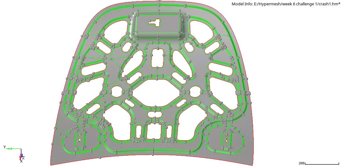
- To mesh the component, under 2D -> Automesh, change the element size to 5mm and mesh type to quad and select half the surface of the component as it is a symmetry component and mesh it
- To obtain a uniform mesh try to remesh the elements and use quality index cleanup tool options.
- Under Tool -> Check elements check for warpage, Jacobian, min/max element length, min/max tria and quad angle, taper, aspect ratio, and skewness if any error is found perform remesh or use cleanup tools to correct that.
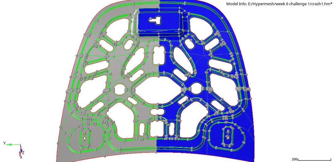
- As leaving the latch surface whole component is symmetric in nature, under Tool -> Reflect select all the elements leaving the latch region, duplicate the elements and choose to reflect along the y-axis with base, select the top point as the base and reflect.
- Under Tool -> Edges, perform the edge check for the reflected elements to delete the open edge.
- If any edge is still open and cannot be closed by Edge option, use Replace option under 2D to close the edge by replacing the nodes. Again perform edge check for open edges if any.
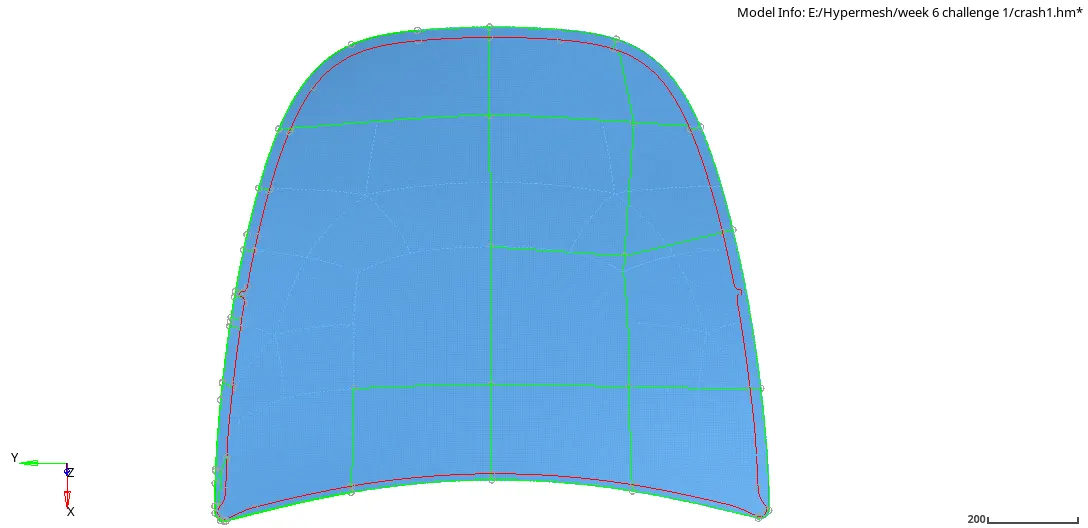
- Now in the component section, hide all and show only the outer body, delete the solid of the outer body, extract midsurface (offset+plane+sweep) of the component and make the extracted mid surface as current than perform manual geometric cleanup of the component.
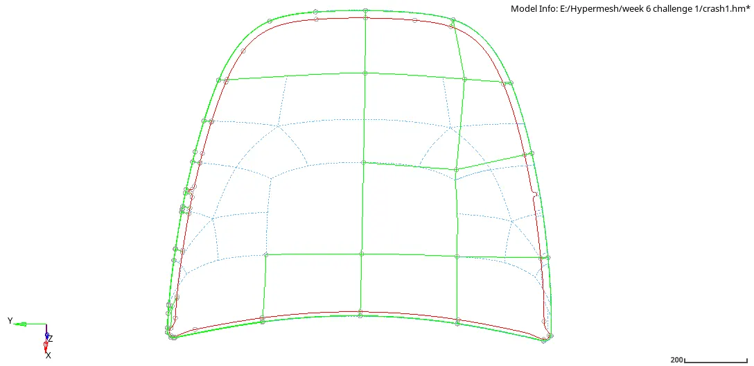
- Mesh the half side of the component Under 2D-> Automesh, if there is any rotating quad try to eliminate by remeshing the elements or using cleanup tools present in the quality index.
- Under Tool -> Check elements check for warpage, Jacobian, min/max element length, min/max tria and quad angle, taper, aspect ratio, and skewness if any error is found perform remesh or use cleanup tools to correct that.
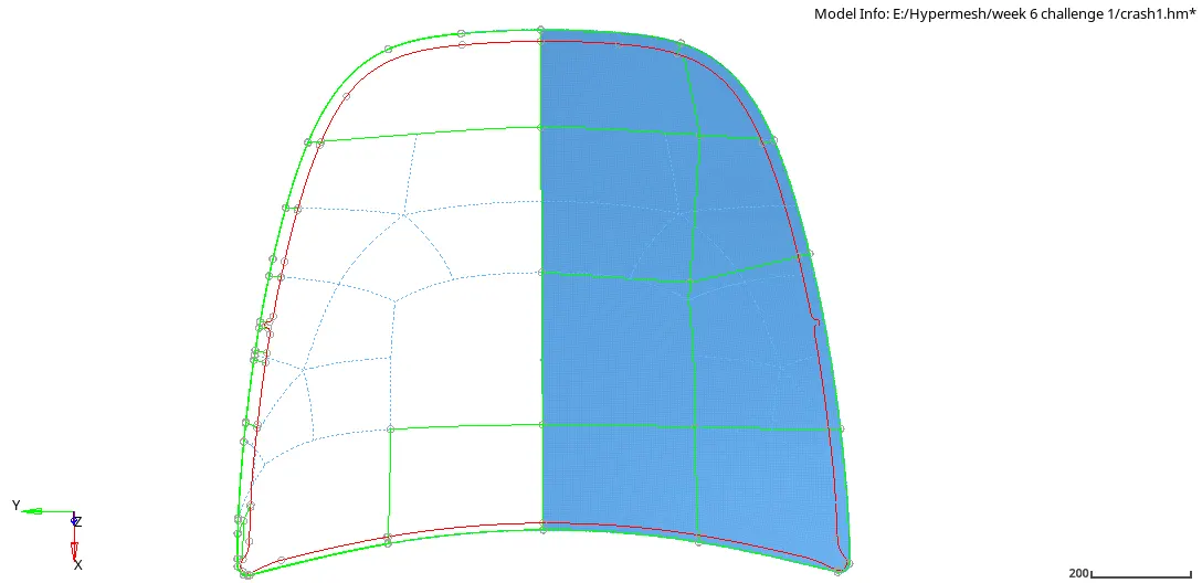
- As the whole component is symmetric in nature, under Tool -> Reflect select all the elements than duplicate the elements and choose to reflect along the y-axis with base, select the top point as the base and reflect.
- Under Tool -> Edges, perform the edge check for the reflected elements to delete the open edge.
- Now in the component section, again hide all and show only the latch reinforcement, delete the solid, extract midsurface of the component (offset+plane+sweep) and make the extracted mid surface as current than perform manual geometric cleanup of the component by toggling the geometric lines, applying washer split, etc.
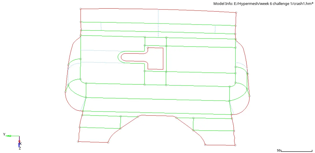
- Under 2D -> Automesh select the displayed surface and element size to 5mm, click on the mesh.
- To remove the rotating quad remesh the elements and use cleanup tools under quality index to get the uniform mesh.
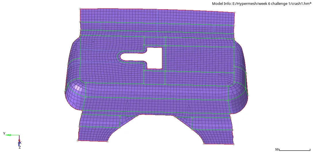
- Under Tool -> Check elements check for warpage, Jacobian, min/max element length, min/max tria and quad angle, taper, aspect ratio, and skewness if any error is found perform remesh or use cleanup tools to correct that.
- Now in the component section, again hide all and show only the hinge reinforcement 1, delete the solid, extract midsurface of the component (offset+plane+sweep) and make the extracted mid surface as current than perform manual geometric cleanup of the component by toggling the geometric lines, applying washer split, etc.
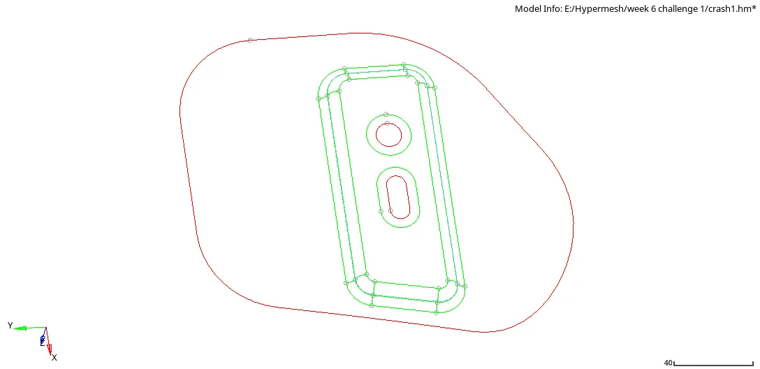
- Under 2D -> Automesh select the displayed surface and element size to 5mm, click on the mesh.
- To remove the rotating quad remesh the elements and use cleanup tools under quality index to get the uniform mesh.
- Under Tool -> Check elements check for warpage, Jacobian, min/max element length, min/max tria and quad angle, taper, aspect ratio, and skewness if any error is found perform remesh or use cleanup tools to correct that.
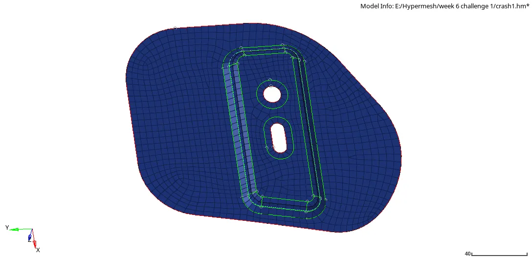
- Now in the component section, again hide all and show only the hinge reinforcement 2, delete the solid, extract midsurface of the component (offset+plane+sweep) and make the extracted mid surface as current than perform manual geometric cleanup of the component by toggling the geometric lines, applying washer split, etc.
- As the hinge reinforcement 2 is symmetric to the hinge reinforcement 1, reflect the elements of the hinge 1 to hinge 2 by using Tool-> Reflect option, select the elements of hinge 1 and duplicate it then chose to reflect along the y-axis with base, in the component section show the extracted mid surface outer body and chose its top point as the base and click on reflect.
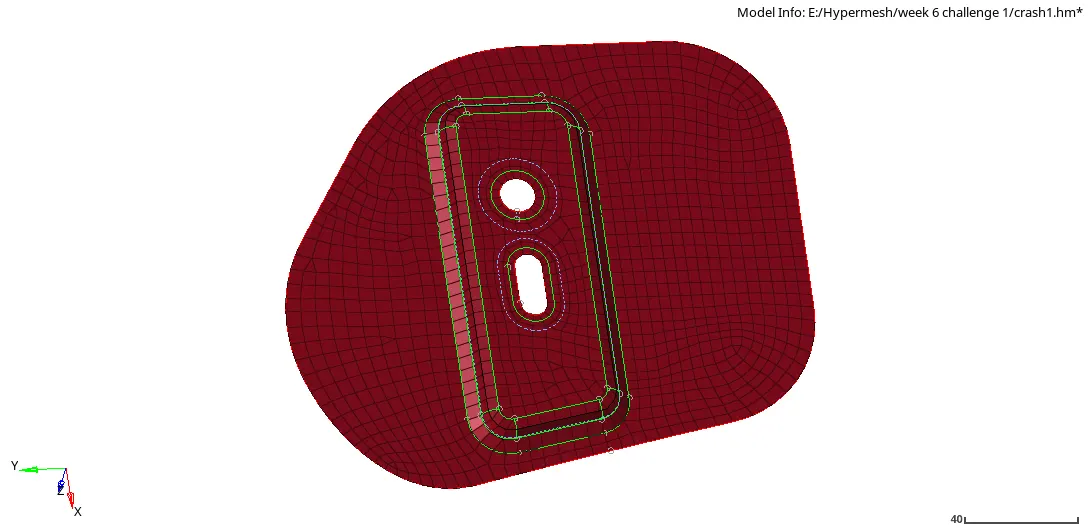
- For all the above component, to align the elements to the geometric line Tool -> project -> to line option is used to align the elements to the geometric lines.
- So after meshing all the components perform a model check like check for normal, dependency, penetration, edges, element to the surface edge, etc.
- In the model section create new material rename it as Steel by default there will be values of young's modulus, Poisson's ratio, density, etc, in the property assign the material as Steel and thickness to 2.5mm.
- Now first check for free edges by Tool -> Edges, select the elements displayed and click on "find edge", if any edge is found select the elements of that free edge and click on "equivalence" if still the edge is open try 2D -> Replace option and replace the nodes to close the edge.
- Element to surface edge check, Toolbar -> Mesh -> Check -> elements -> comparison -> Source entities "elements" -> Select all the elements displayed on the graphic screen -> Proceed -> Target entities "surface" -> select the surface displayed on the graphic screen -> Proceed -> tolerance value "0.2" -> Run. It will display the entire geometry capture, so yellow and pink is fine but there should not be any red colored elements, if there is any try to align with the geometric lines by Tool -> Project -> to surface -> select the element -> select the surface and nearby surface -> select the vectors -> project.
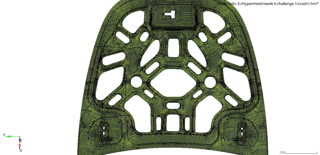
- Similarly geometry check can be performed, Toolbar -> Geometry -> Check -> Surface -> comparison -> Source entities "elements" -> Select all the elements displayed on the graphic screen -> Proceed -> Target entities "surface" -> select the surface displaye on the graphic screen -> Proceed -> tolerance value "0.2" -> Run, yellow and pink is fine but there should not be any red colored elements.
- Check Normal, Tool -> Normal -> elements -> display, if it is in color type one side should appear blue and other by red, if in vector type all the arrows of the element should point in the same direction, if any surface has an opposite color or arrow select the element to reverse the normal.
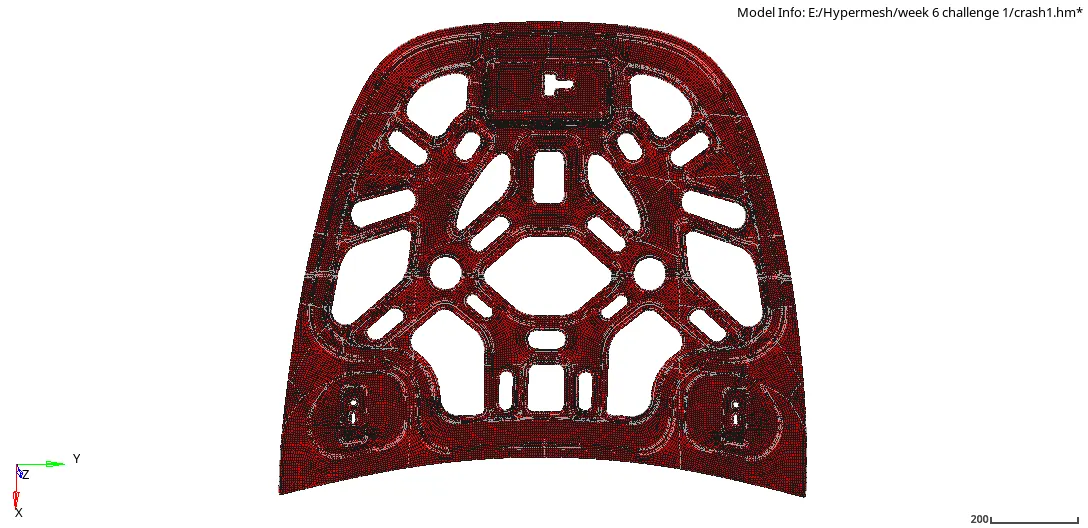
- Check Dependency, Tool -> Dependency -> elements -> select elements displayed -> click dependency, it should show "0 nodes found with multiple dependency".
- Check Penetration, assign the created property to the component then Tool -> Penetration -> elements -> displayed elements -> check, it should show "no intersection and penetration found", if property and thickness are not assigned then it will show an error "unspecified thickness".
- Repeat the check with all the components.
Result:-
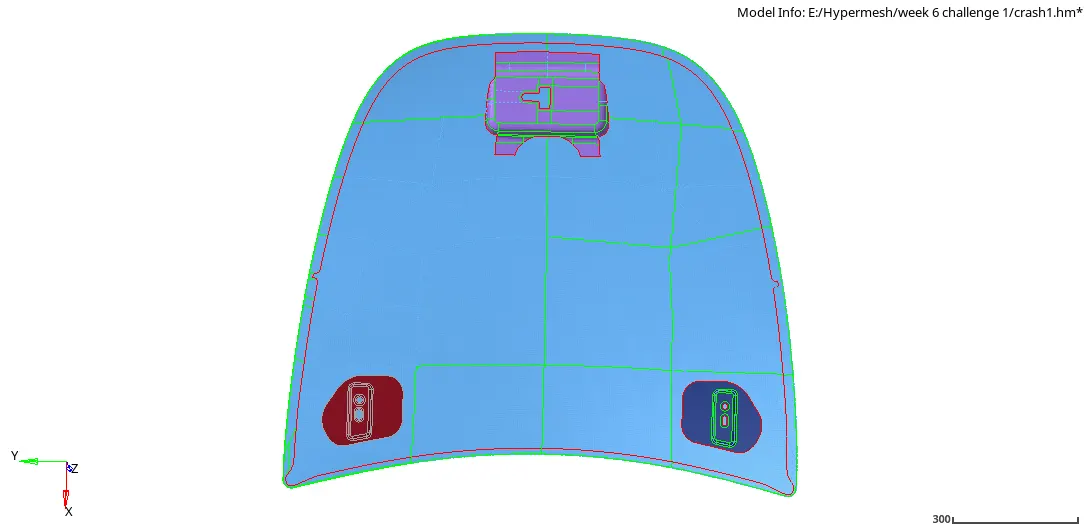
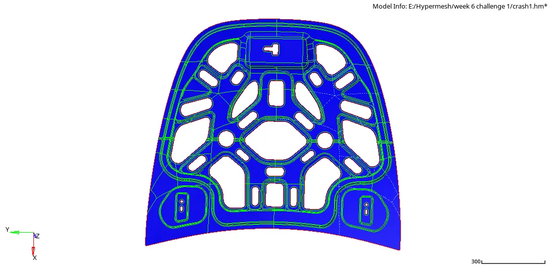
Conclusion:-
So by completing this challenge, I learned how to mesh components for given quality criteria by extracting the midsurface by auto midsurface then after meshing how to perform a quality check of the elements and finally how to perform the model check and assign thickness to the component.