To mesh the hood component according to given quality criteria and assign thickness in ANSA
Objective:- To mesh the given component according to the quality criteria given and also assign the thickness to the components.
|
S.No |
Quality Criteria |
Value |
|
1 |
Target/Average length |
5 |
|
2 |
Minimum Length |
2 |
|
3 |
Maximum Length |
7 |
|
4 |
Aspect |
3 |
|
5 |
Warpage |
15 |
|
6 |
Skewness |
45 |
|
7 |
Jacobian |
0.7 |
|
8 |
Minimum Quad Angle |
45 |
|
9 |
Maximum Quad Angle |
135 |
|
10 |
Minimum Tria Angle |
30 |
|
11 |
Maximum Tria Angle |
120 |
|
12 |
Tria Percentage |
15 |
Procedure:-
- Open ANSA and open the component file which is in ".stp" as provided.
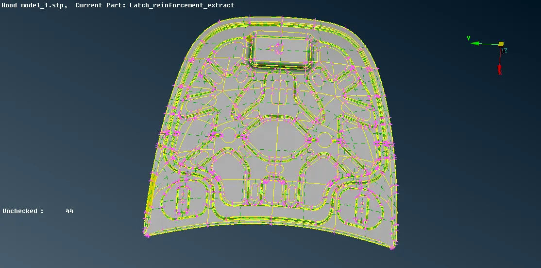
- As there are different entities, first isolate all the entities into different collectors one by one by using the option of "Focus" like or, and, not, !Not, invert, lock and neighbour etc.
- Select "or", choose any one surface then use the "Neighbour" by "All", now by using "store lock" from the "Lock" the entities can be stored separately from one another, repeat these steps for all the other entities to store in different store lock.
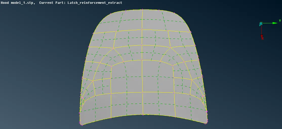
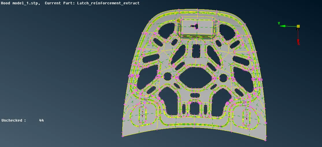
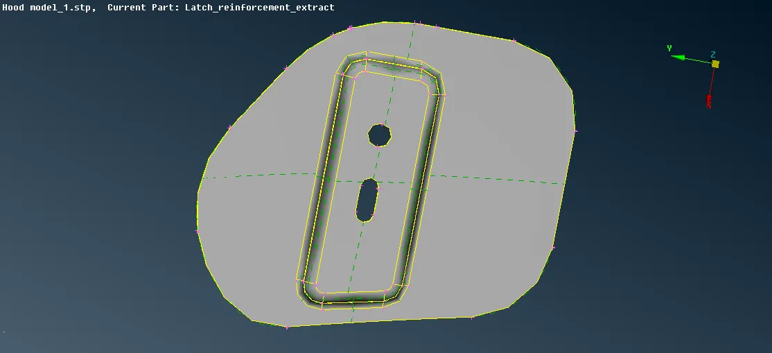
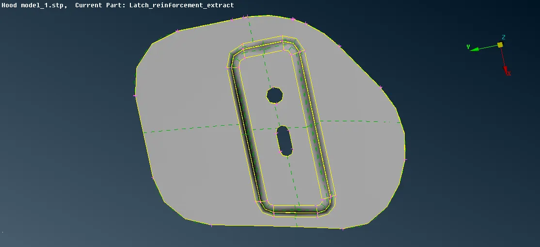
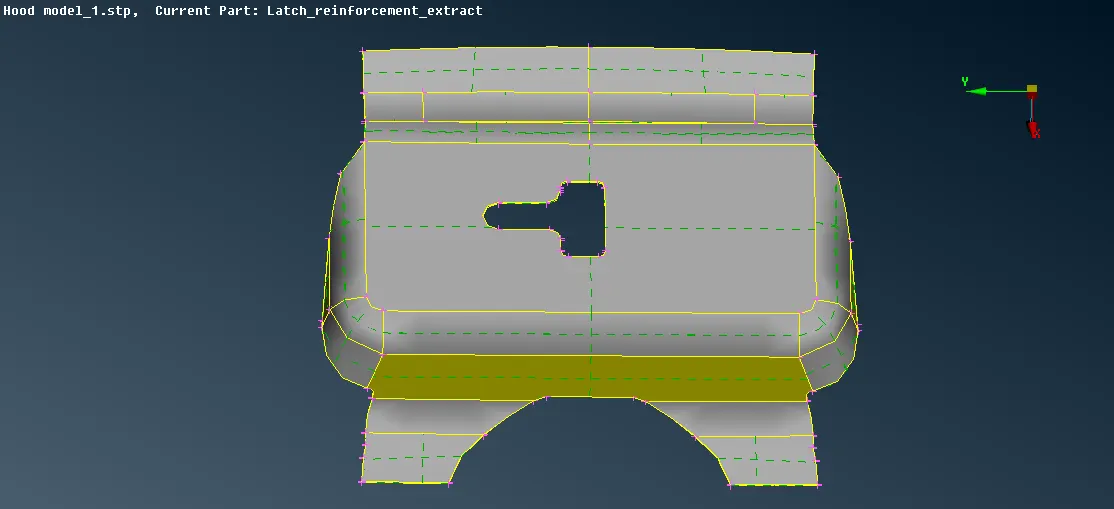
- From the "Utilities" menu, use the "measure" option to check the thickness of each component and assign the measured thickness to the respective component using the "Property" option from the "Lists" menu also even the orientation of all the component by using "Orient" option which is under Modules -> Topo -> Faces.
- Now one by one check the entities for any geometrical error by using the "Geometry" option from the Tools -> Check -> Geometry (from the options select single cons also). If any error found it can be fixed automatically by right click on the error and click on the fix or it can b solved manually by using different options of "Topo" present in modules.
- To extract midsurface of the entities, "Midsurface" by "Skin" option present under "Modules -> Faces -> Mid. Surface" can be used as the entities present are of uniform thickness by using midsurface by skin the midsurface can be extracted easily. After selecting midsurface by skin select the entities top and the bottom side will be represented by red and green colour and thickness by blue, middle-click on the mouse to confirm, now select any one side to extract the midsurface, a new window will popup showing estimate offset thickness and thickness of entities click on "offset", this will create the mid surface.
- Now isolate the mid surface by using the option from the "Focus" and create a separate store lock for the midsurface by using the "Lock".
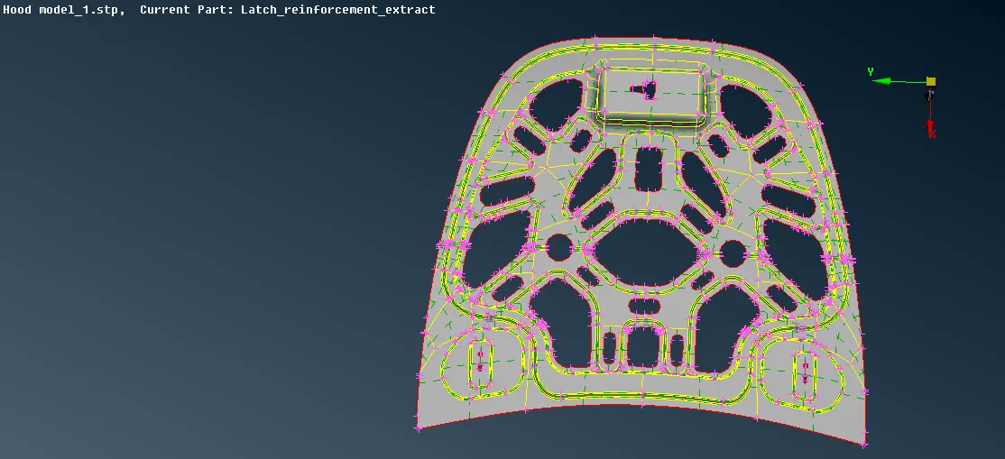
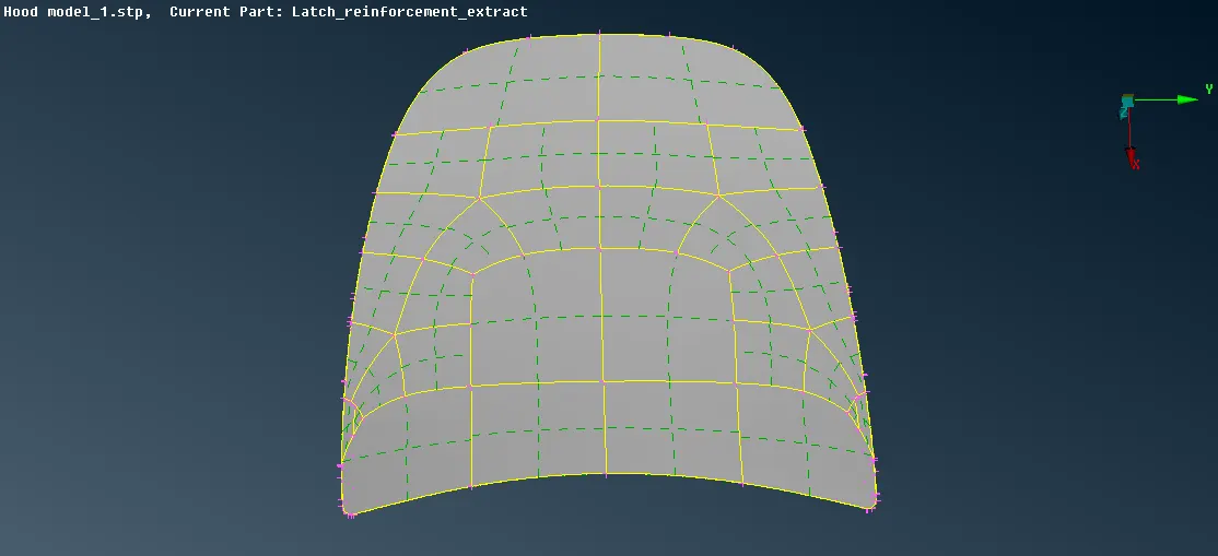
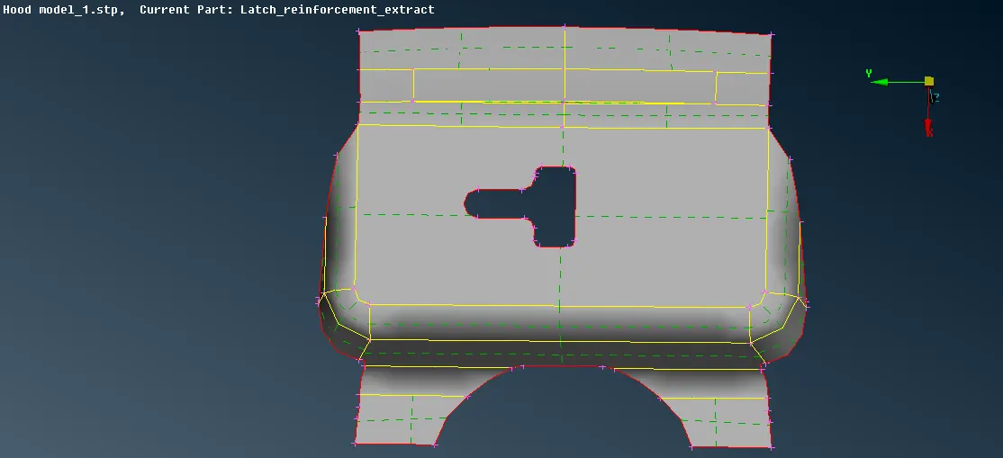
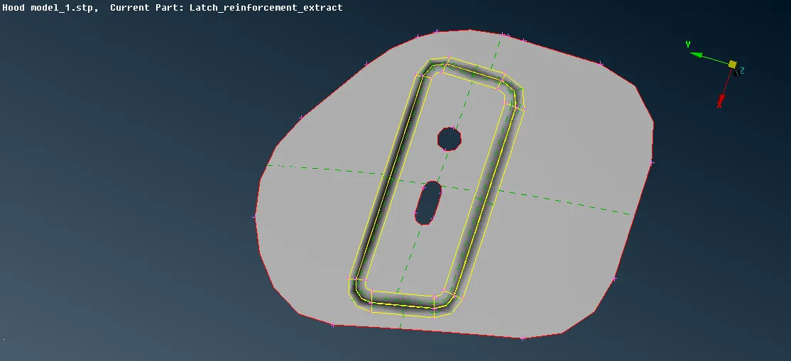
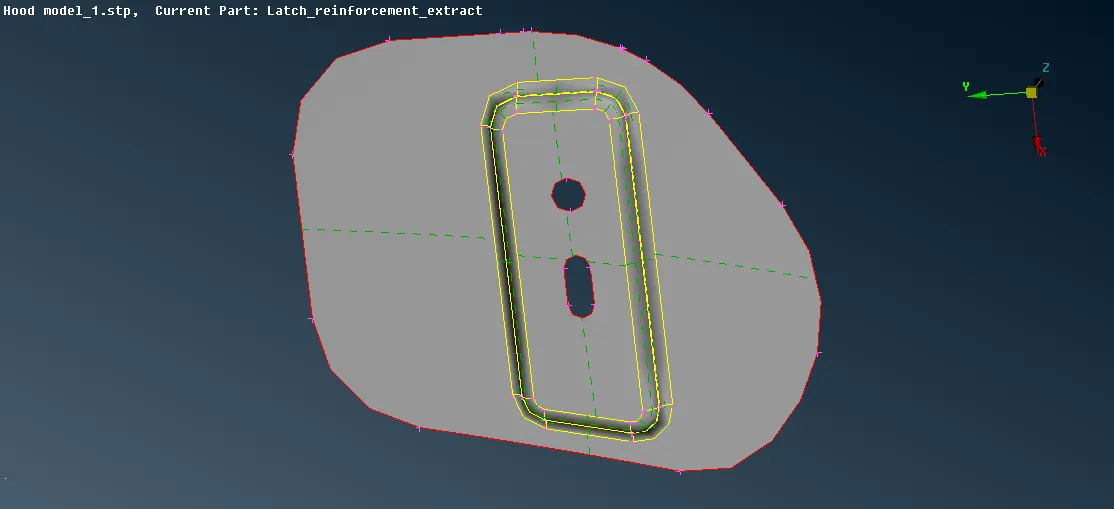
- There are 2 entities which have the symmetric surface, so one surface can be deleted, so to confirm whether the surface is symmetric or not use Modules -> Topo -> Faces -> Rm. Dbl -> Symmetry Plane -> the symmetric area will be highlighted by blue and green select any one colour to delete.
- As the mid surface of all the components have been extracted perform topology clean up of the entities as it will help to generate better mesh flow, topology clean up can be performed by using the options present in Modules -> Topo -> Hot points, Cons, Faces, Auxiliaries etc.
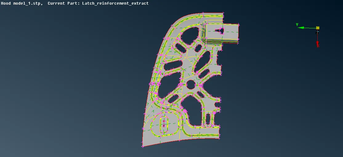
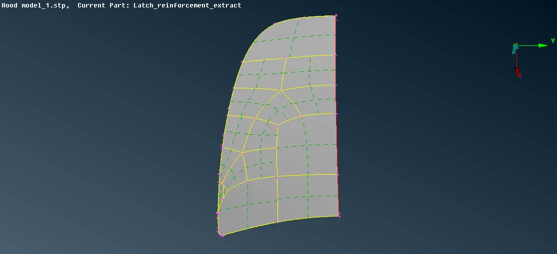
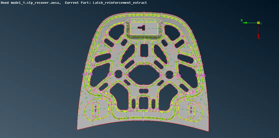
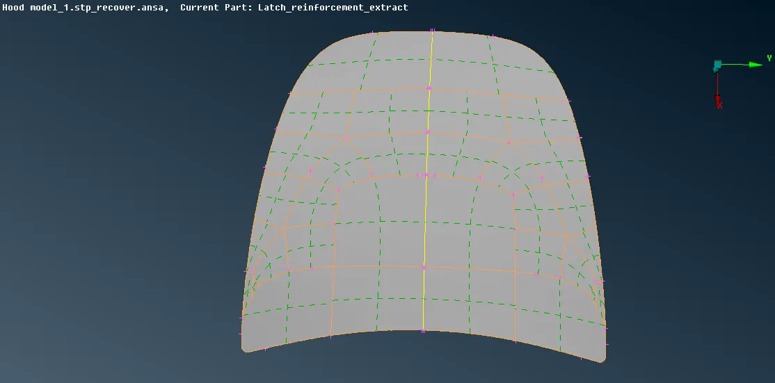
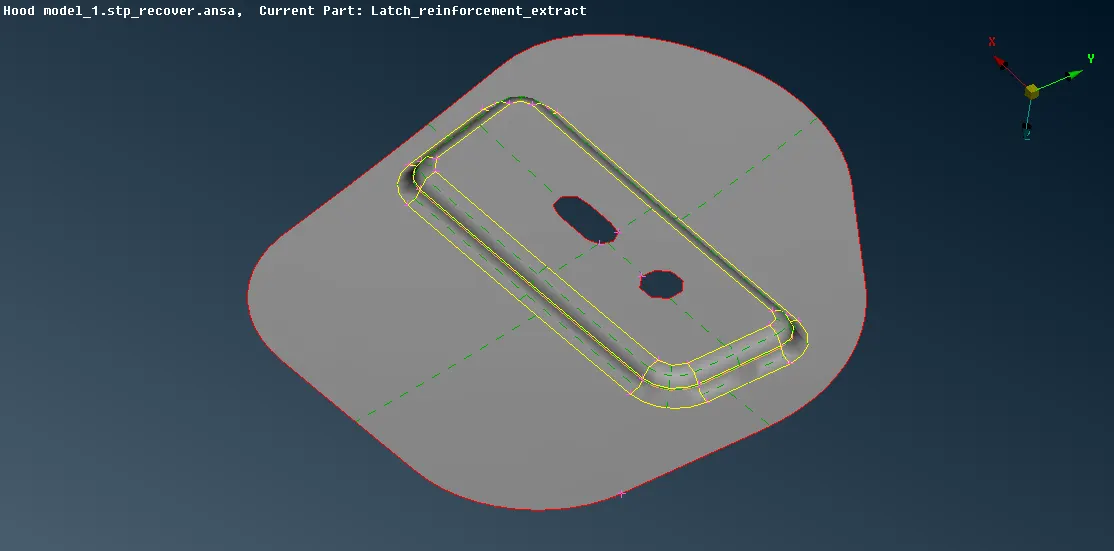
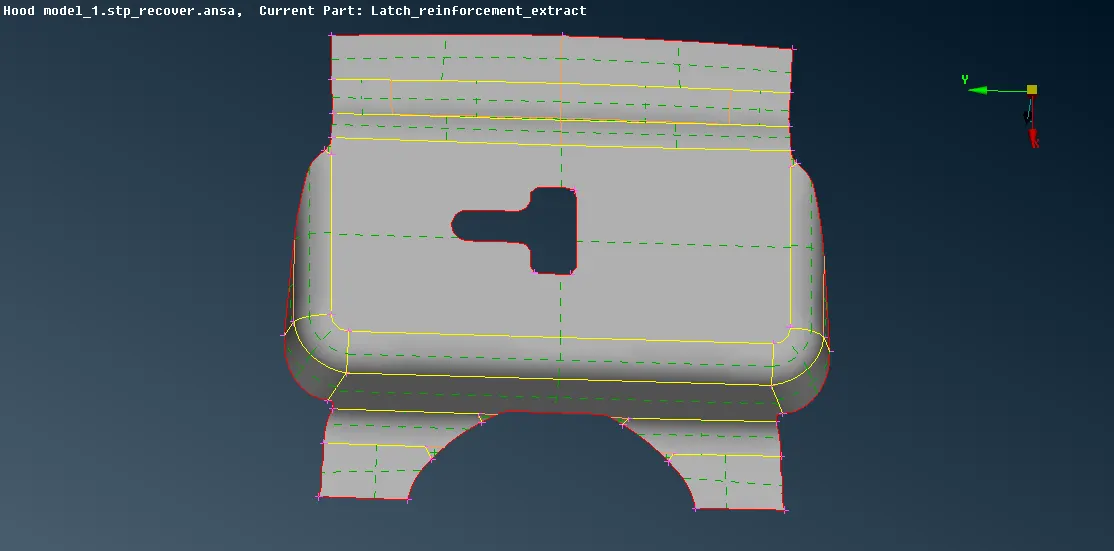
- Now before meshing set the quality criteria and the parameter by using "Quality Criteria" and "Mesh parameter" form the "Utilities". Also, set the length for the entities by Modules -> Mesh -> Perimeter -> Lenth -> for both Perimeter and Macro select the visible entities and provide the values.
- Mesh one by one the extracted midsurface by Modules -> Mesh -> Mesh generation -> Best -> Select the entities .
- The elements can be remeshed and rotating quads and off elements can be removed by using the option in Shell Mesh -> Reconstruction or using the option in Elements -> Split, Swap or combination of the mentioned process.
- To refine the meshed surface use "Smooth" option present under "Shell Mesh'.
- After meshing the one half of the symmetric component it can be mirrored by using Utilities -> transform -> Copy -> Entities -> Select the visible entities -> middle mouse click to confirm -> Symmetry -> Default Symmetry Plane -> Apply -> Finish.
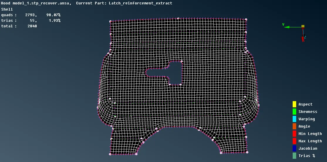
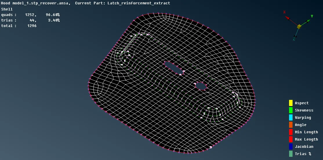
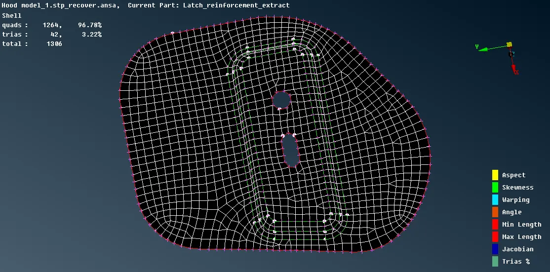
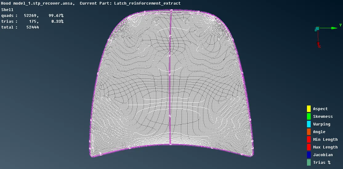
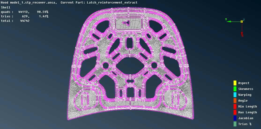
- Once the mesh is done and all rotating quads are removed and the mesh is refined release the elements from the midsurface by Modules -> Mesh -> Elements -> Release -> select the elements -> middle mouse click to confirm.
- Now to view the shell as solid elements, in Utilities -> Quality Criteria -> Presentation Parameters -> Elemets -> check Draw shell as solid -> Ok
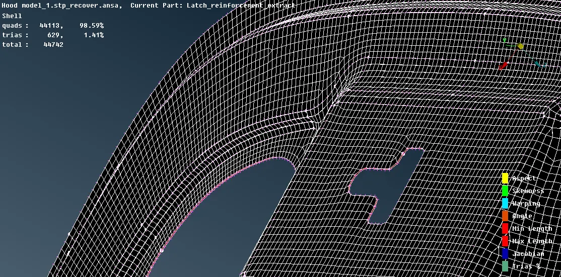
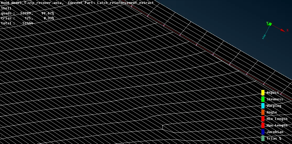
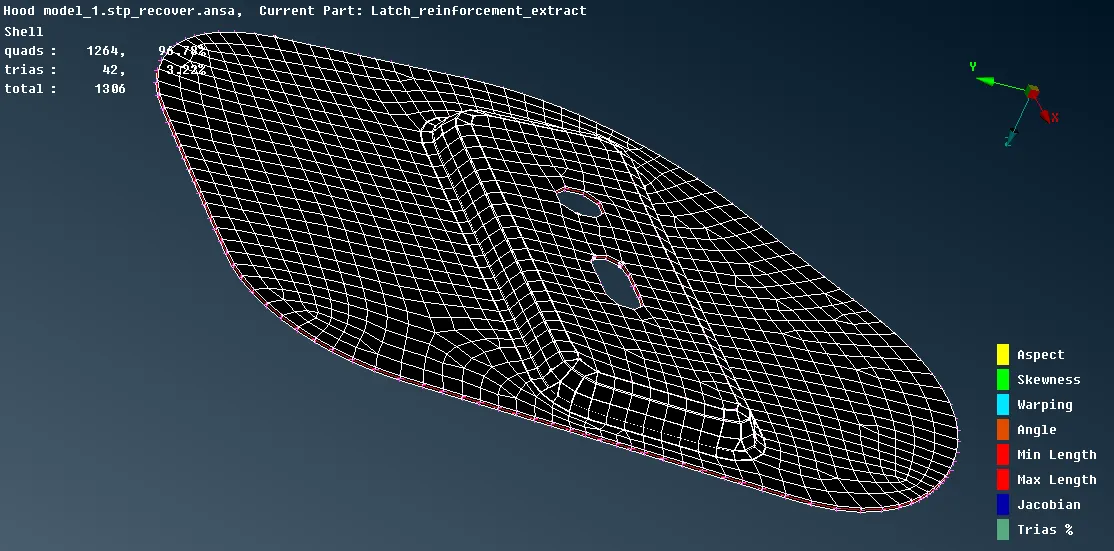
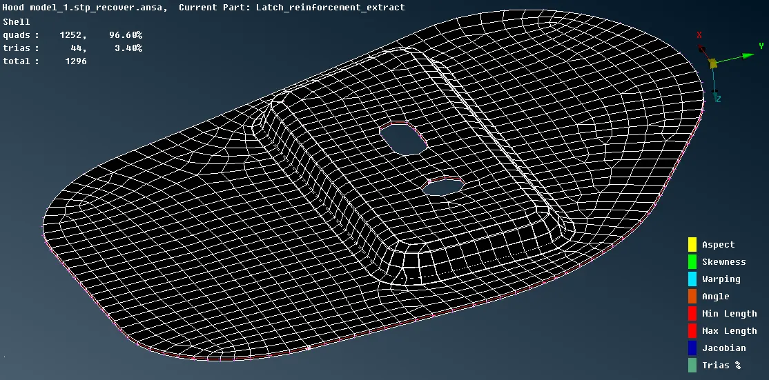
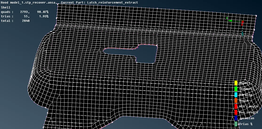
Result:-
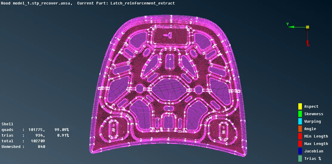
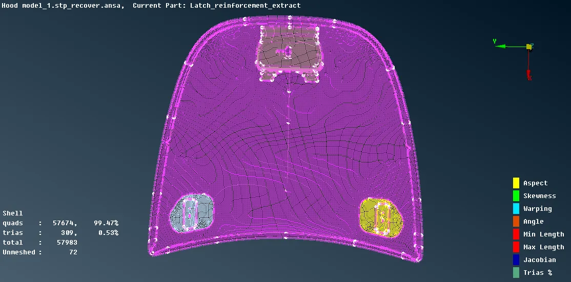
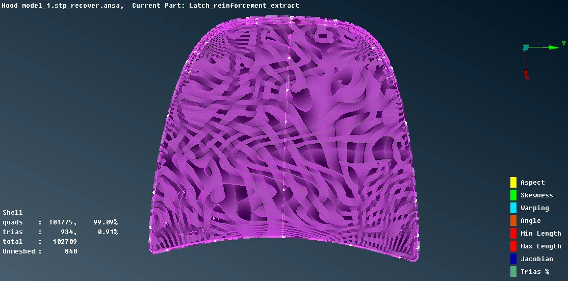
Conclusion:-
So by completing this challenge, I learned how to mesh hood component according to given quality criteria by extracting midsurface and then performing the mesh after that how to perform the quality check and resolve rotating quad and trias for better mesh flow and also finally how to assign thickness.