Implementing different types of connection on the rear door in ANSA
Objective:- To implement different types of connections on the rear door FE model.
Procedure:-
- Open Ansa and open the component file via input -> NASTRAN, as the file is in ".nas" type.
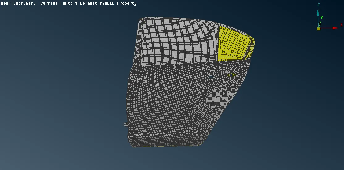
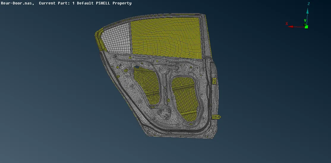
- To apply bolt connection manually on a region,
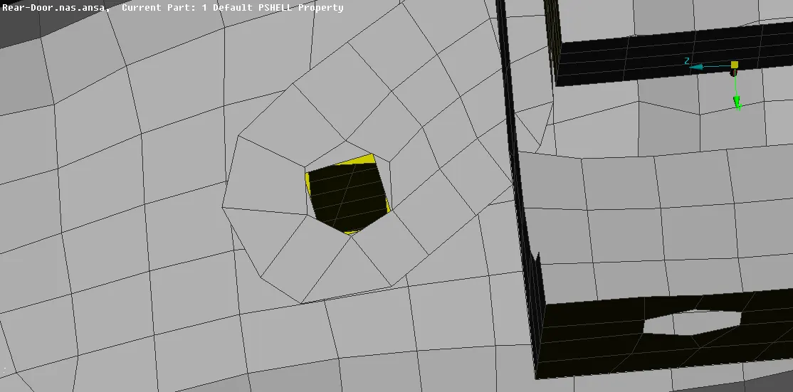
- In the modules -> NASTRAN -> Elements -> RBE2 -> Many nodes -> select the nodes of the hole which will be slave nodes (by loop) -> master node will assigned automatically, next -> CM is DoF= 123456, change Part = Ask always -> Finish -> In model browser assign a part by creating a new part -> ok.
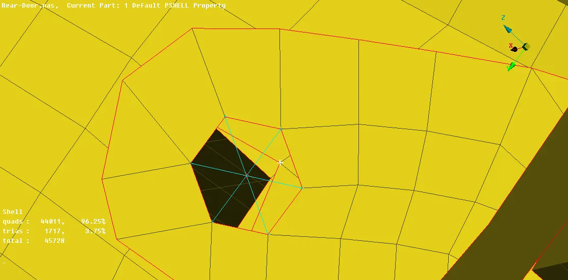
- Similarly, create a RBE2 Many node connection for the bottom hole
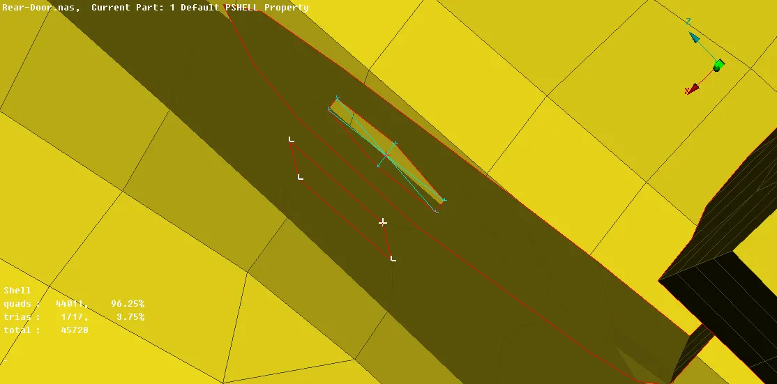
- After creating the RBE2 many node connection on both hole connect the master node of the 2 holes via RBE2 two nodes, by modules -> NASTRAN -> elements -> RBE2 (Two node) -> select the 2 master node -> ok
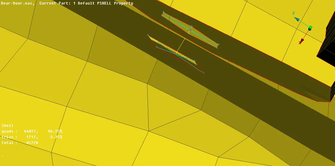
- Similarly in holes wherever bolt connection is required it can be applied by the above method.
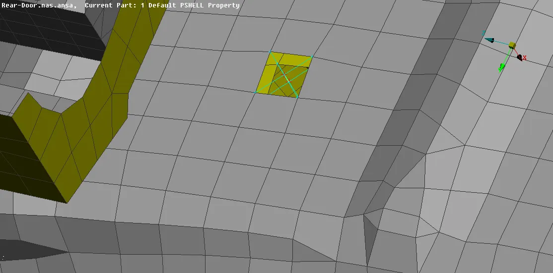
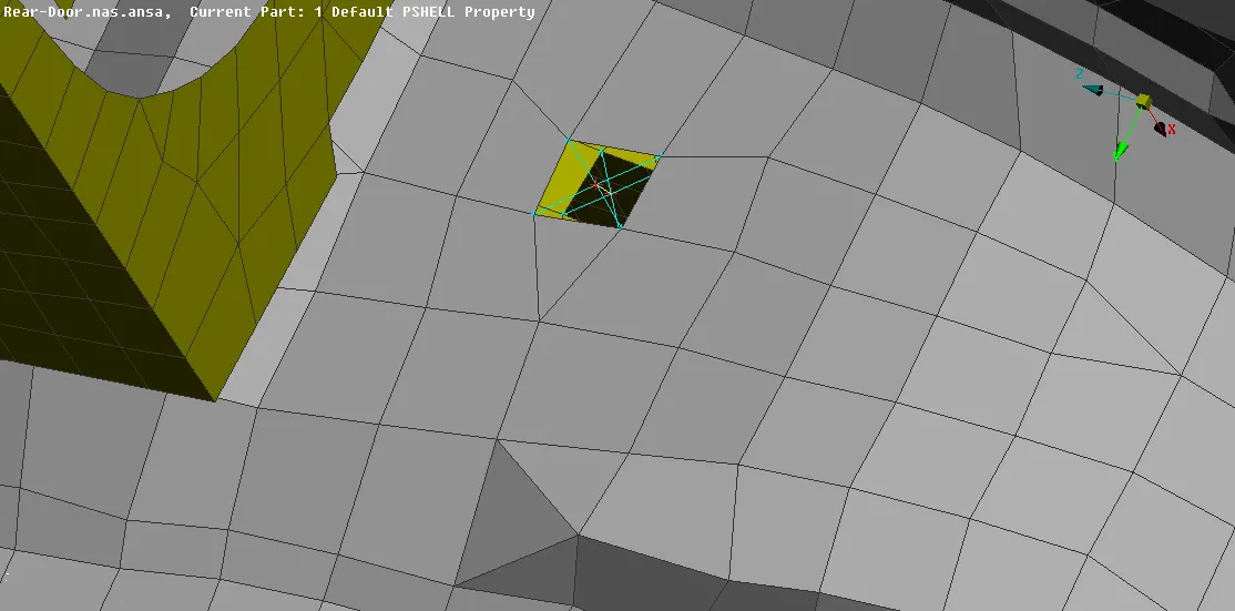
- To apply cluster RBE2 connection,
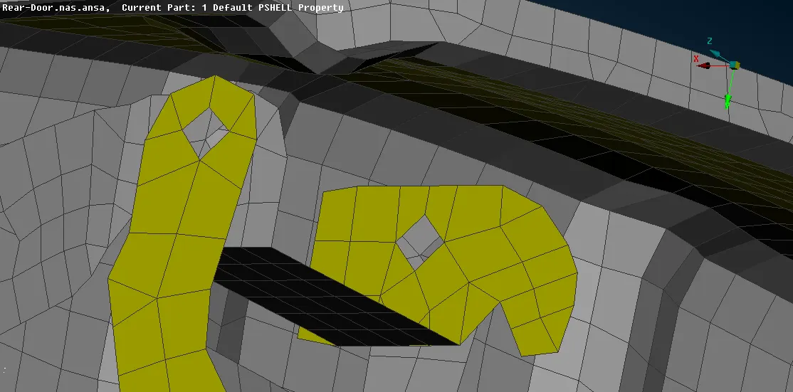
- In the modules -> NASTRAN -> Elements -> RBE2 -> Many nodes -> select the nodes of the both hole which will be slave nodes (by loop) -> master node will assigned automatically, next -> CM is DoF= 123456, change Part = Ask always -> Finish -> In model browser assign the already created part-> ok.
- Repeat the steps for the other hole of the hinge.
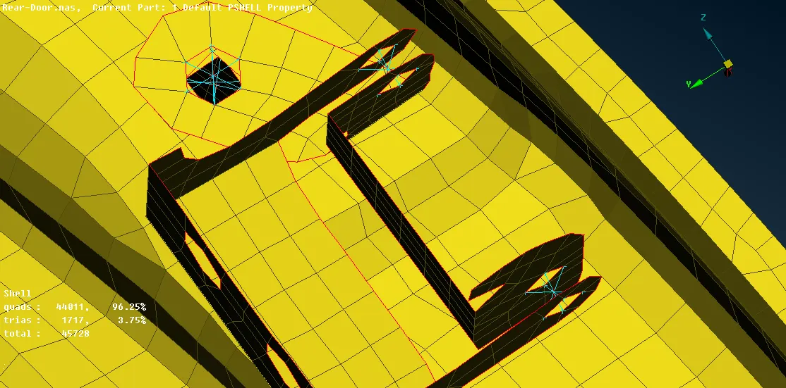
- To connect the 2 master node of the cluster RBE2, modules -> NASTRAN -> elements -> RBE2 (Two node) -> select the 2 master node -> ok
- As the door open and close action depends on this part and it happens on Z-axis rotation, so the door only be constraint on 3 translational and 2 rotational axis allowing the Z-axis rotation.
- The constraint of the element can be chaned by, modules -> NASTRAN -> Elements -> Info -> select the 2 node RBE2 -> in CM provide only 12345 (CM is DoF).
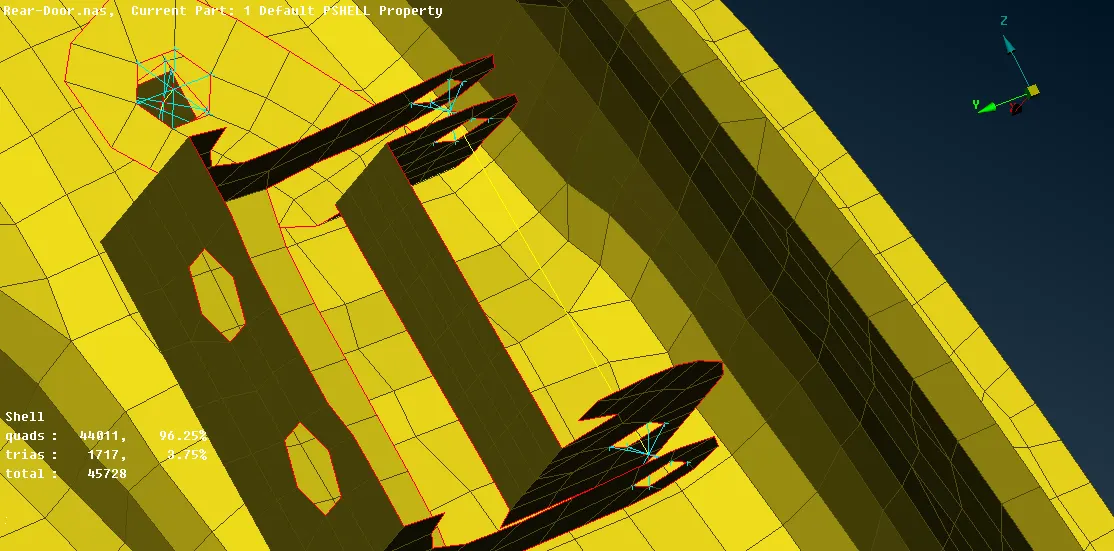
- Similarly, other hinges also can be assigned
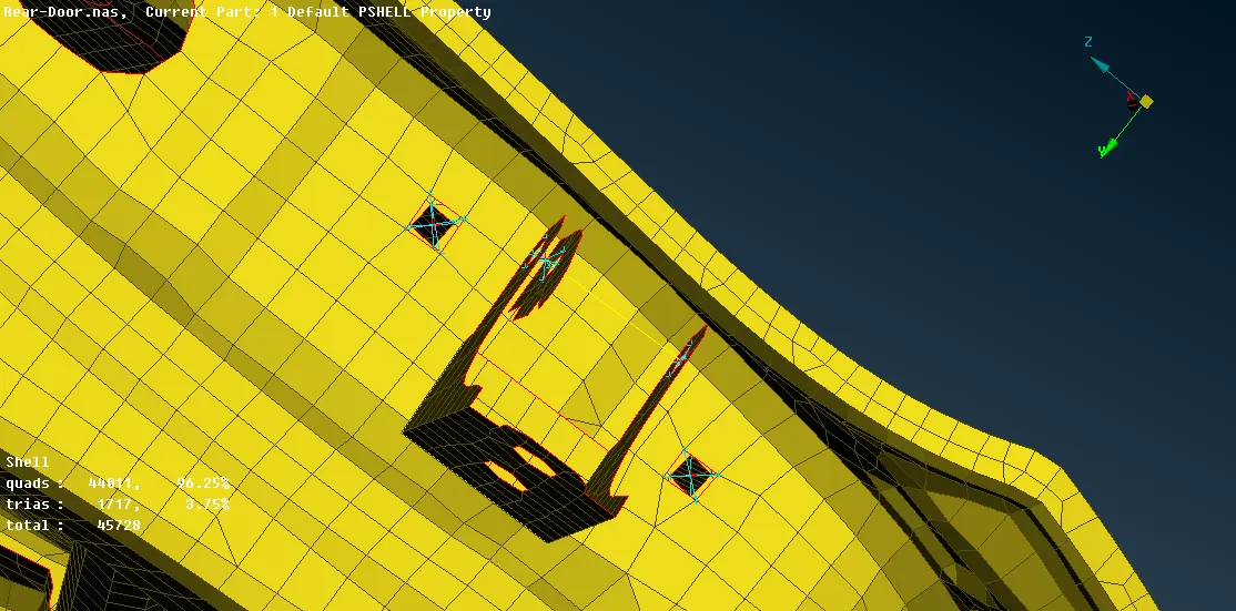
- The door lock can be represented as,
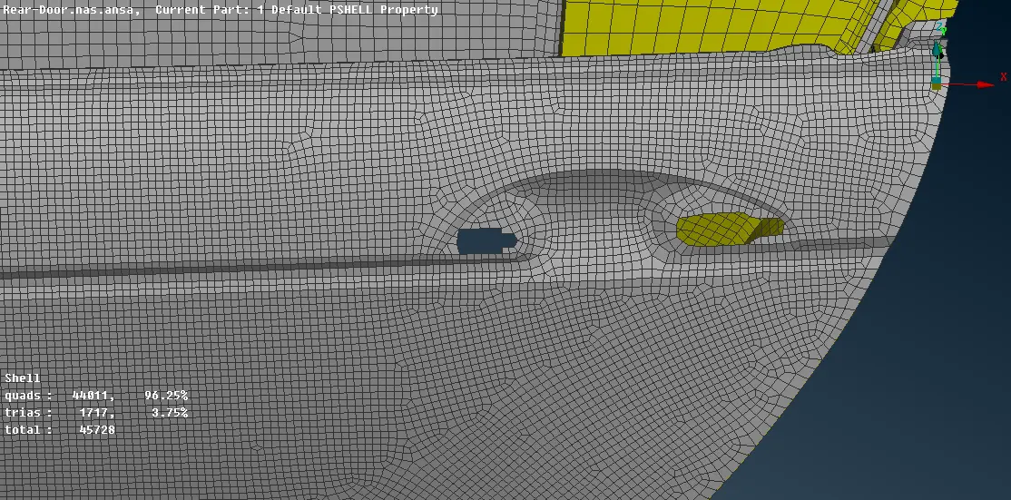
- The two holes should be individually assigned RBE2 many nodes, by modules -> NASTRAN -> Elements -> RBE2 -> Many nodes -> select the nodes of the hole which will be slave nodes (by loop) -> master node will assigned automatically, next -> CM is DoF= 123456, change Part = Ask always -> Finish -> In model browser assign the already created part-> ok.
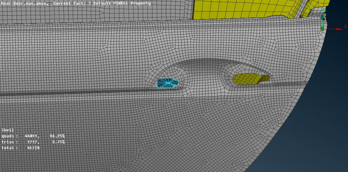
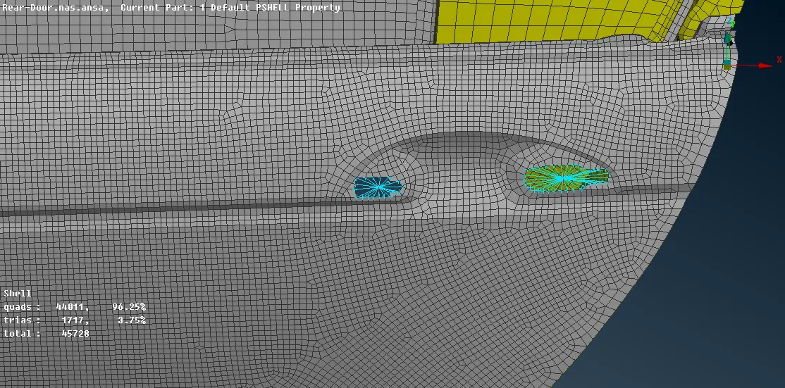
- After assigning the RBE2 to the holes, join the master node of both the holes via RBE2 many nodes to represent the door handle.
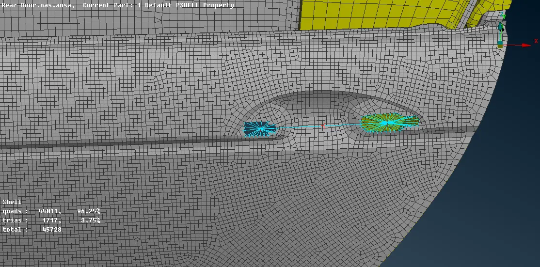
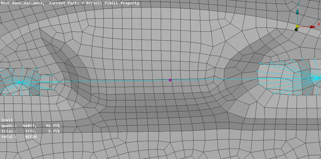
- The RBE2 element joining the 2 master nodes representing the door handle should be assigned mass, modules -> NASTRAN -> Elements -> CONMi -> CONM2 (nodes) -> select the nodes to assign -> middle mouse click -> in M provide the mass value in units on "tonnes" -> ok.
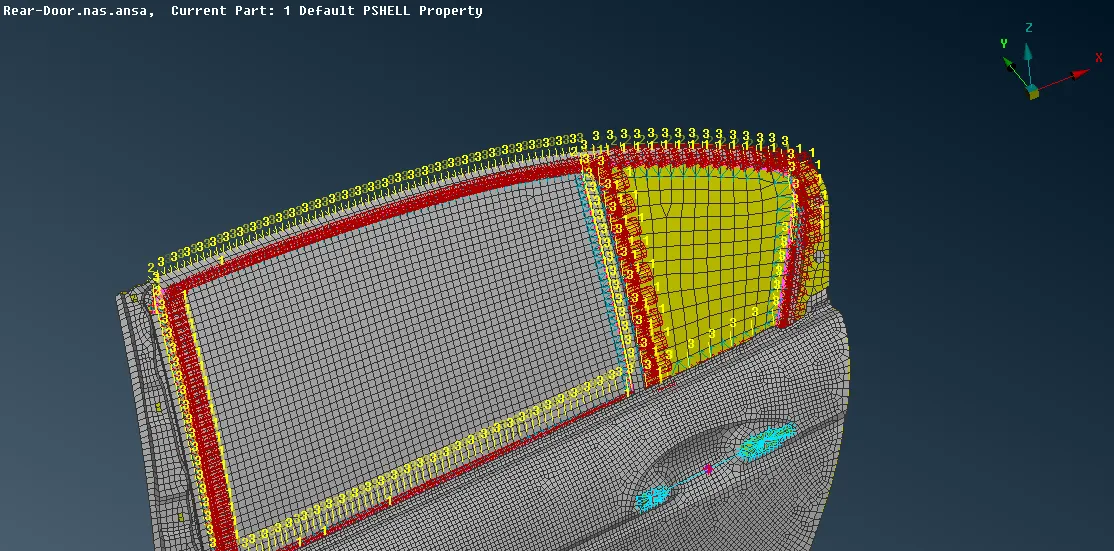
- The connection between the window glass with the door needs to be represented by RBE3-CBUSH-RBE3.
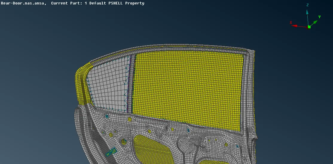
- To apply RBE3-CBUSH-RBE3 we need to first create curve, the curve can be generated from FE model by, modules -> mesh -> perimeters -> Feat2curve -> select the edges of FE (by loop) -> middle click to confirm.
- After generating the curve, convert the curve to spotline individually by, assembly -> convert -> curves -> select the curve -> spotline -> ok. Convert one curve line at a time.
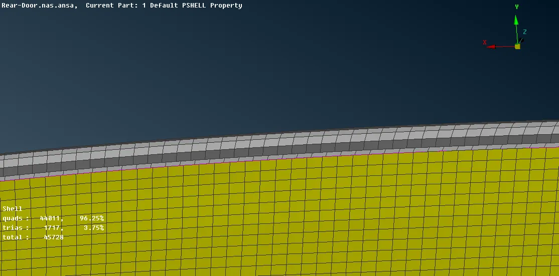
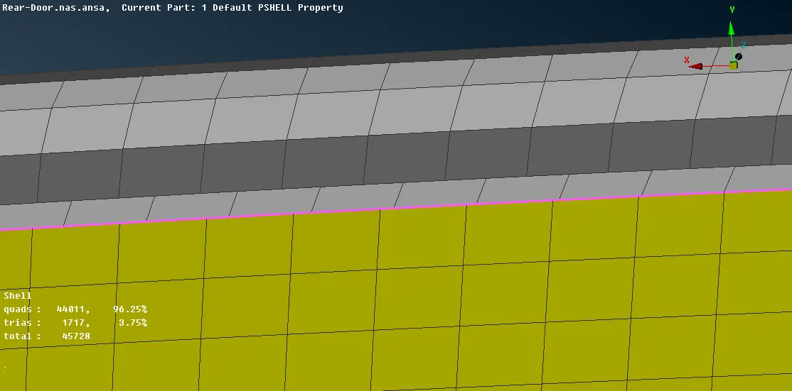
- To assign and realize the curve to RBE3-CBUSH-RBE3, assembly -> connection manager -> select one curve -> middle mouse click -> in the connection manager dialogue box, first assign P1 and P2 one by one -> right click on P1 -> click on modify -> press F1 -> select the part which be chosen as P1 -> middle mouse click -> hit enter -> assign P2 in similar way -> "S" represent the spacing between the CBUSH, assign value by right click on it -> FE Rep Setting, FE Rep Type = RBE3-CBUSH-RBE3, sereach distance = 20 , keep all branches = check, PBUSH ID (to assign shift + /) = create a new ID where assign values to K1 to K6, ok, double click to assign that ID -> Apply -> Realize. CBUSh will be assigned to the curve. Similarly assign CBUSH to other curves of glass window.
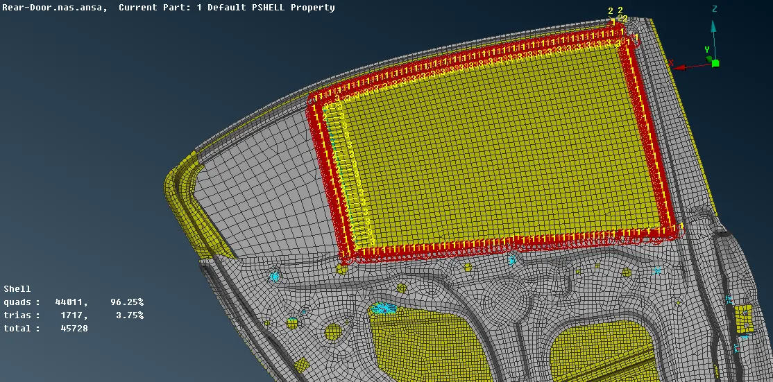
- Similarly RBE3-CBUSH-RBE3 can be assigned to the other glass window by first creating a curve out of FE model, than converting the curve to spotline and finally assigning and realizing RBE3-CBUSH- RBE3 by connection manager.
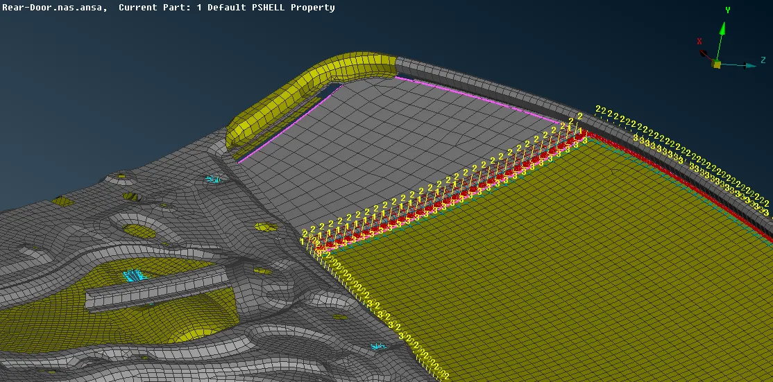
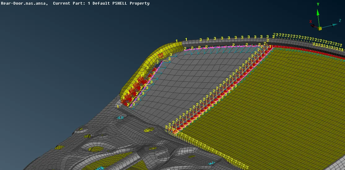
- As the RBE3-CBUSH-RBE3 have their own local coordinates and are oriented according to their attachment with P1 and P2, all the local coordinate should be oriented in one direction with respect to global coordinate to do that, DATABASE (F12) -> ELEMENTS -> CBUSH (double click) -> in the cbush panel, show/hide columns enable "orient" and "CID" -> as there are numerous CBUSh, select all, right click, modify -> in modify panel under Modify Rules = orient, with cord -> add another by clicking "+" -> select CID -> provide value 0 -> ok -> click on yes. All the CBUSH local coordinate will be oriented with respect to global coordinate.
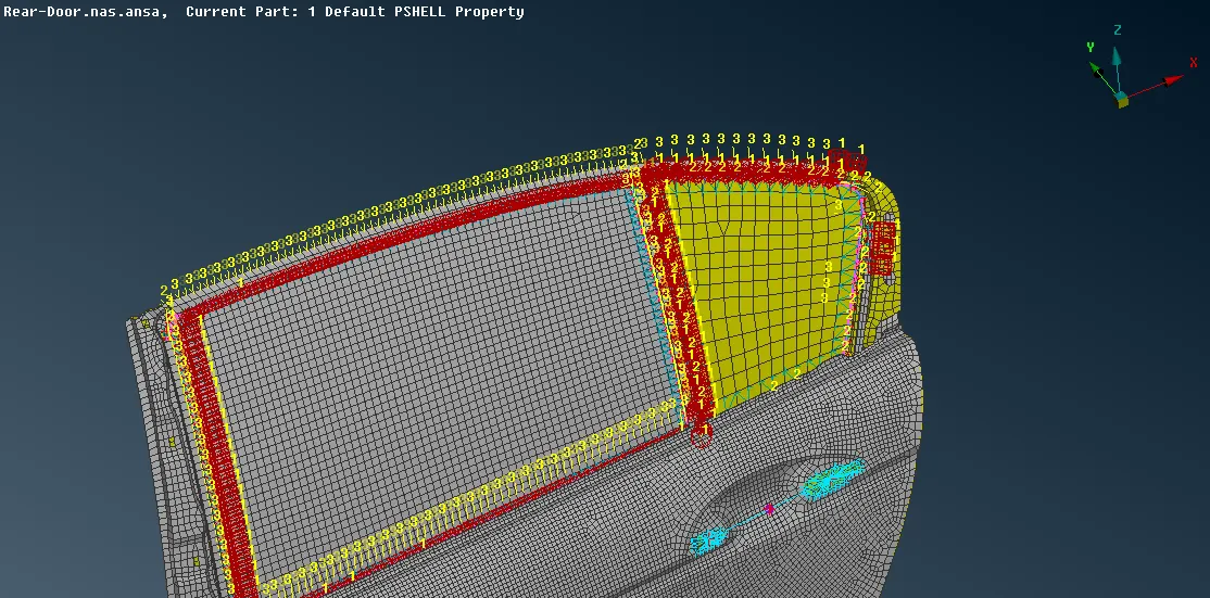
- Spotweld connection by RBE3-Hexa-RBE3
- Before applying and realizing spotweld, first, create 3Dpoints which can be done by modules -> topo -> points -> OnCog -> select the edge of elements -> middle mouse click to confirm.
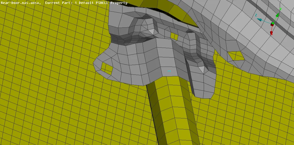
- After creating 3Dpoint convert it to spotweld point by, Assembly -> Convert -> 3D point -> select the 3D point -> spotweld point -> ok.
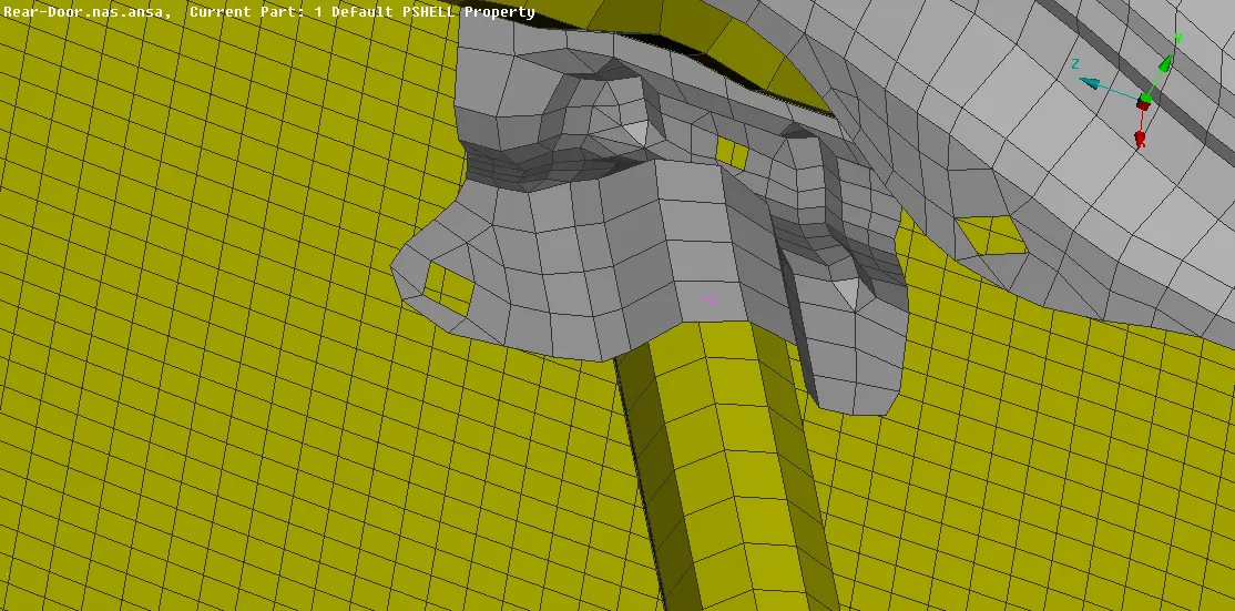
- Now to assign and realize the spotweld connection, Assembly -> connection manager -> select the "spot weld point" -> middle mouse click -> in connection manager window assign P1 and P2 one by one (right click -> modify -> F1 -> select the part -> middle mouse click -> press enter) -> FE Rep Setting -> FE Rep Type = RBE3-Hexa-RBE3, Search Distance= 30, RBE3 Pinflags= 123456, PSOLID ID (to assign shift + /)= create a new PSOLID ID, ok, double click to assign the ID ->Apply -> Realize. The spot weld will be assigned and realized.
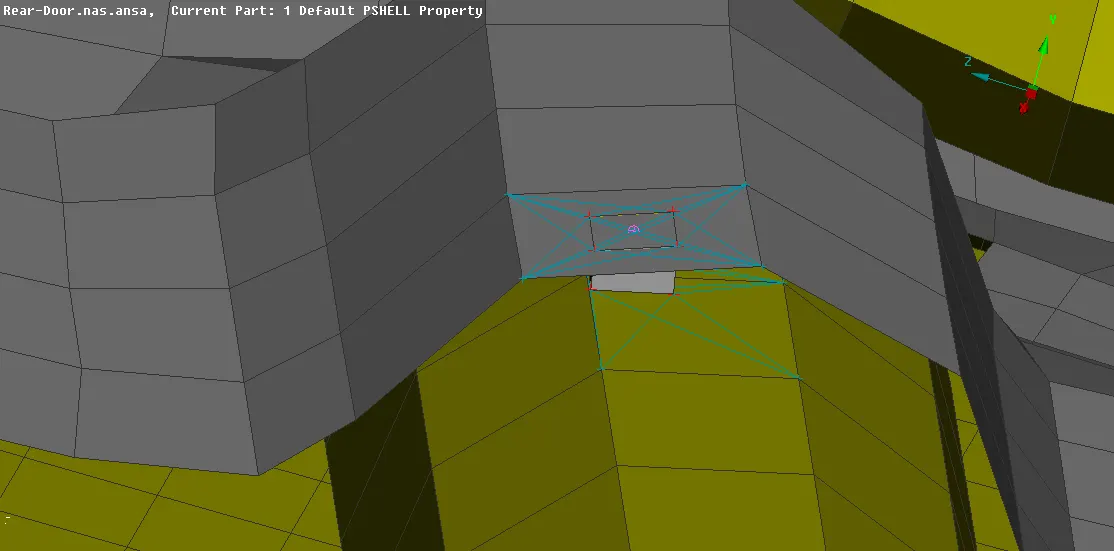
- Similarly at other places also spot weld can be applied.
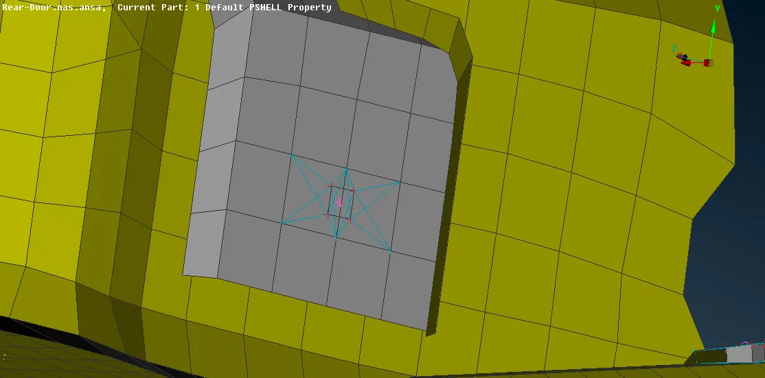
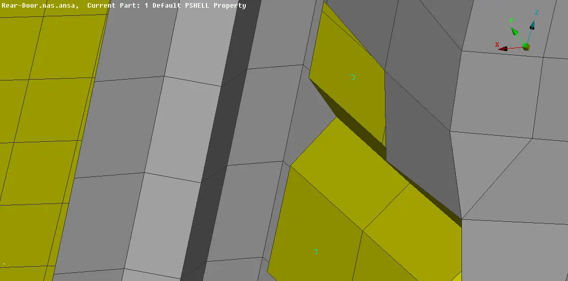
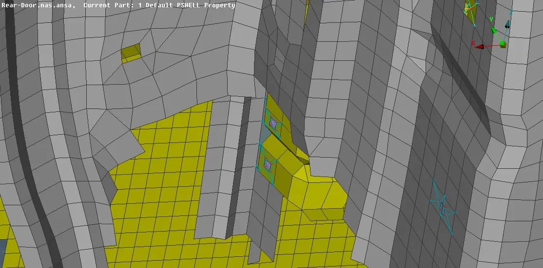
Result:-
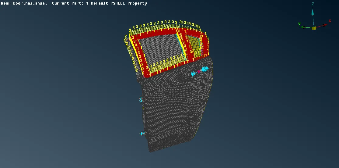
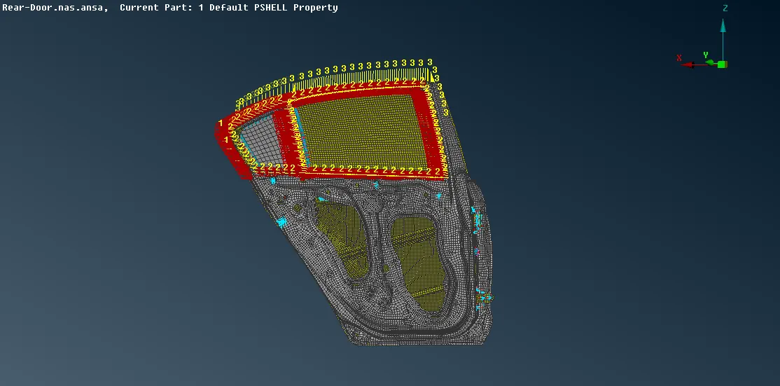
Conclusion:-
So by completing this challenge, I learnt how to assign and realize different types of connection to rear door like weld (spot and seam weld), bolt (RBE2 = many node and two node) connection both manual and automatic assigning process, spring elements like cbush also how to assign mass.