Week- 5 - Solid meshing
Aim:
For the given Rearview mirror component, check for the geometrical errors and mesh the Surfaces with the given 2D element Quality criteria given below.
Procedure:
- Open the Ansa software and import the given Rearview Mirror component.
- After importing the model, click on the Topo option in the Faces tools in the Topo deck to define the topological conditions for the given model.
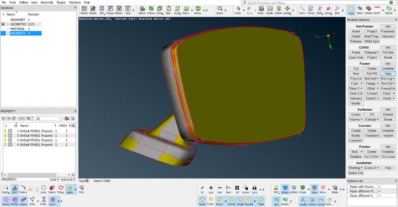
THE REARVIEW MIRROR MODEL WHEN IMPORTED INTO THE SOFTWARE
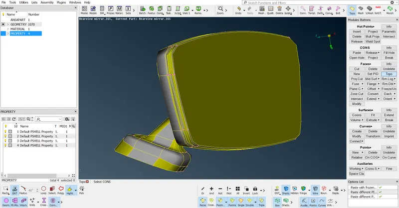
THE REARVIEW MIRROR MODEL AFTER THE APPLYING THE TOPO
- Click on the Topo option in the Faces tools and select the whole surface and Middle click to confirm the action.
- Apply the target element length on the selected perimeter segments or macro areas to apply the mesh as per the given element criteria & also for the better mesh flow on the model.
- To apply the target length, change to the Mesh mode from Topo mode, select the Length option in the Perimeters, select the whole surface & enter the given target element length value and click the middle-click on the mouse to confirm the task.
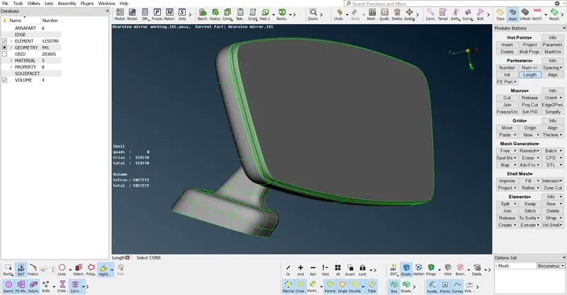
THE REARVIEW MIRROR MODEL AFTER APPLYING THE TARGET ELEMENT LENGTH
- There are 4 components present in the given Rearview Mirror model, click on the model browser on the left side of the graphic area at the top to select the component to be worked on and hide all the rest of the components. For example, select the Mirror component and hide all the rest of the components.
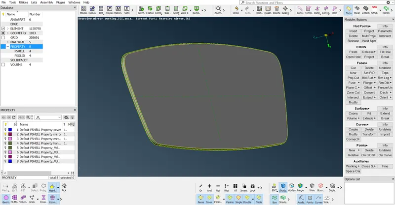
WORKING ON THE MIRROR COMPONENT & HIDING THE REST OF THE COMPONENT
- After selecting the required component, check the model if the model has any geometrical errors like needle faces, triple cons etc. If any errors like these present in the given model try to remove them with the help of the CHECKS tool present at the top of the graphic area.
- Click on the CHECKS tool from the dropdown list select the Geometry option. Upon entering into the Geometry window, check on the Active button and change the option for the Execute on option to Visible and click on the Execute button. The errors present in the model will be displayed.
- Click on the errors one by one and right-click and select the option Fix which means the error will be automatically fixed by Ansa if possible and if it is not possible it needs to be fixed manually.
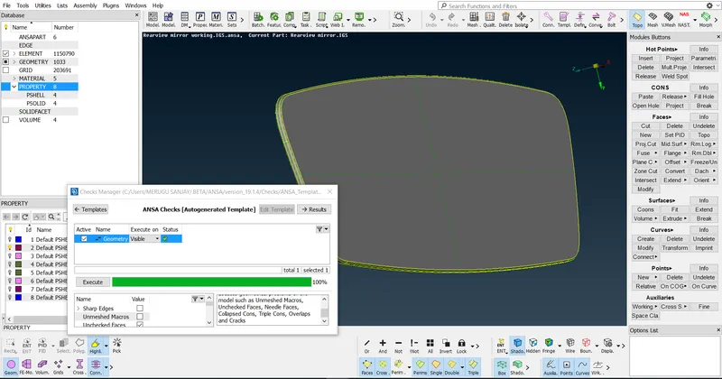
THE STATUS SHOWS THERE ARE NO GEOMETRICAL ERRORS IN THE CHECKS WINDOW FOR THE MIRROR COMPONENT
- After clearing all the errors, try to mesh the component using the Tria & Ortho Tria elements.
- Enter the values for the given component in the Mesh parameters window, change the type of the elements from Mixed to Ortho Tria & also in the Quality criteria or press the F11 function key to open the window enter the values for the likes of Minimum length, Maximum length and for the Tet collapse.
- After applying the target element length on the Mirror component try to mesh the component. Keep the Mesh mode as it is and click on the Best mesh in the Mesh Generation.
- Select a face on the component and middle-click to generate the mesh. The mesh generated on the selected face, if the mesh pattern was not good try to reconstruct the mesh by using the Reconstruct tool in the Shell Mesh tools.
- Wherever there are the curved regions try to apply the Ortho Tria elements mesh and apply the Tria elements mesh on the flat surfaces.
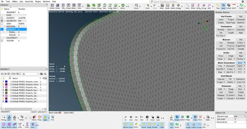
ORTHO TRIA ELEMENT MESH ON THE BENDING PORTION AND TRIA ELEMENTS MESH ON THE FLAT PORTION
- If there are any mesh elements failing for the given quality criteria, try to clear them by using the different tools.
- For example, if any less number of elements failing for the Minimum Elements Size try to clear them manually by using the Split option in the Elements tools by splitting the elements.
- In the Mesh mode and at the bottom there are the Elements tools present. In these Elements tools, there are options like Split, Join, Swap etc are present use these tools to clear the mesh quality manually.
- After splitting the elements, the mesh pattern will be disturbed and then use the Smooth tool in the Shell Mesh tools to smoothen the disturbed mesh pattern. If there are a huge number of elements that are failing for the quality try to use the Reconstruct tool present in the Shell Mesh tools.
- After applying the 2D Tria and Ortho Tria mesh, apply the 3D Tetra mesh on the component.
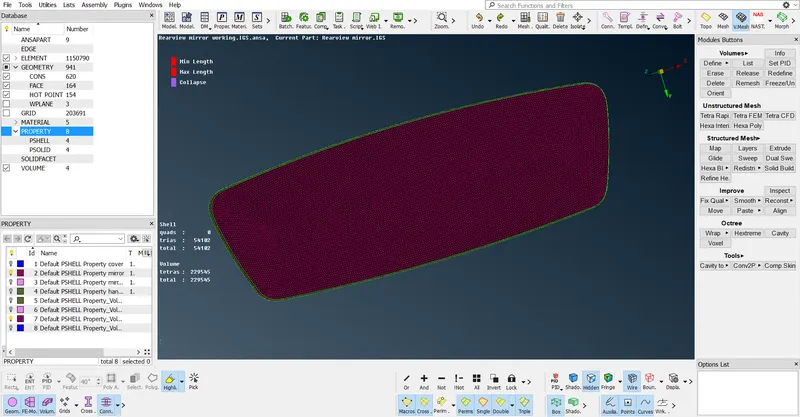
MIRROR COMPONENT WITH 2D MESH APPLIED ON IT
- Click on the Volume Mesh deck, select the Volumes and click on the Define option.
- In the popup window, in the work on option change the Whole DB to visible option & there is a property created in the popup window and it shows the mesh is undefined.
- Right-Click on the property created and select the Remesh option and select the Tetra Rapid algorithm from the list of algorithms available.
- Middle-click to apply the Tetra mesh with Tetra rapid algorithm.
- After applying the Tetra mesh, check for the number of OFF elements and also for Tet Collapse. Clear all the tet collapse failed elements.
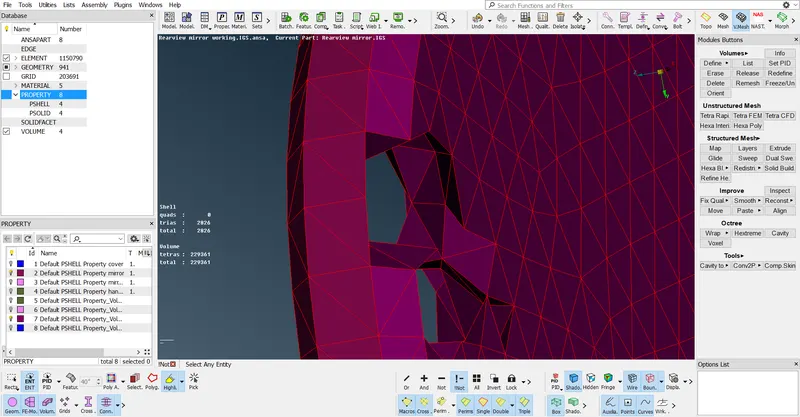
MIRROR COMPONENT WITH 3D TETRA MESH INSIDE THE SURFACE
- Repeat the same procedure for the rest of the components and apply the 3D tetra mesh in the same way.
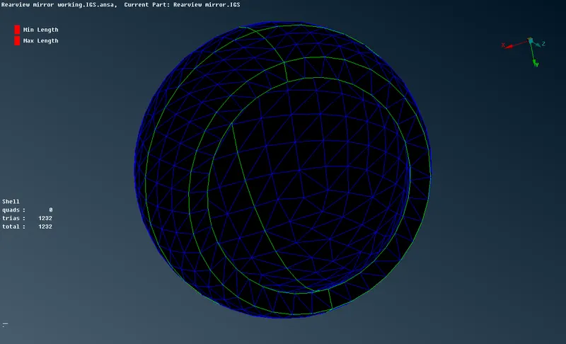
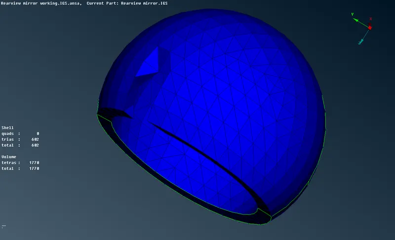
3D TETRA MESH OF THE HANDLE COVER
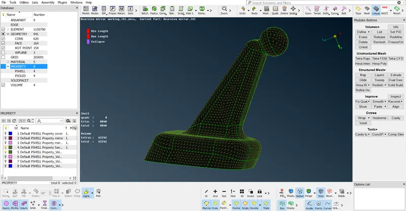
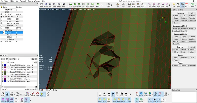
3D TETRA MESH OF THE MIRROR HANDLE
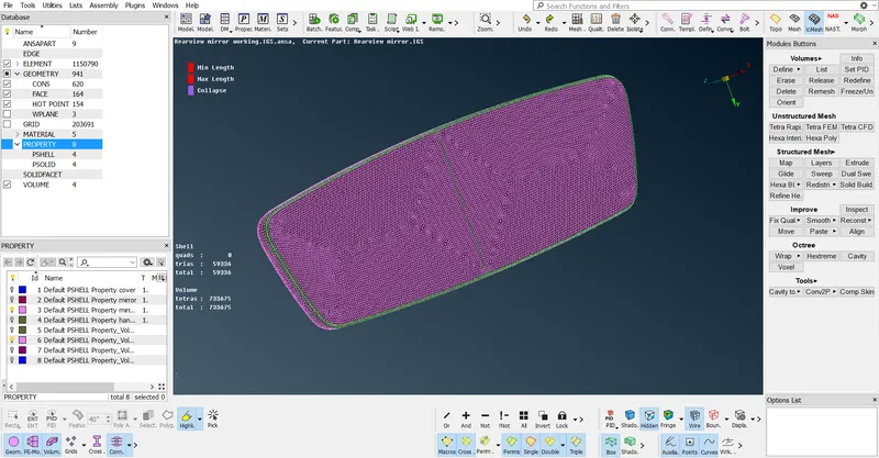
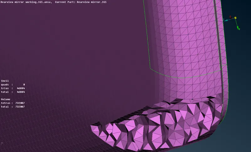
3D TETRA MESH ON THE MIRROR HOLDER COMPONENT
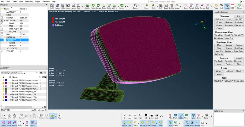
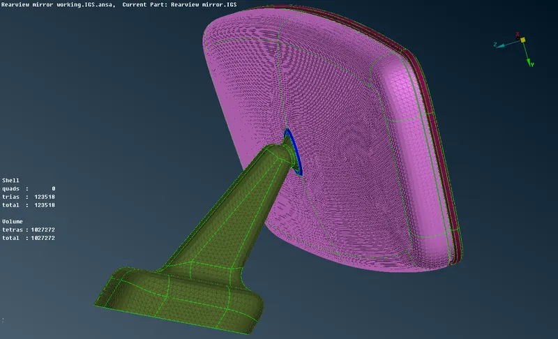
ALL THE COMPONENTS OF THE REARVIEW MIRROR MODEL WITH TETRA MESH
Conclusion:
For the given Rearview Mirror model, the geometric errors have been checked, the 3D Tetra mesh is applied on all the surfaces and the quality is checked according to the given quality criteria.