Week 5:- Rest Unit & Clamp Unit Design Challenge
CLAMP UNIT AND REST UNIT DESIGN
AIM:
To design 3 Different types of Power Clamp Unit with Different Riser, Blade, and Clamp Arm and design 2 Different types of Rest Unit for the given Car Panel.
INTRODUCTION
The principle of location is being discussed here with the help of a most popular example which is available in any of the book covering jigs and fixtures. It is important that one should understand the problem first.
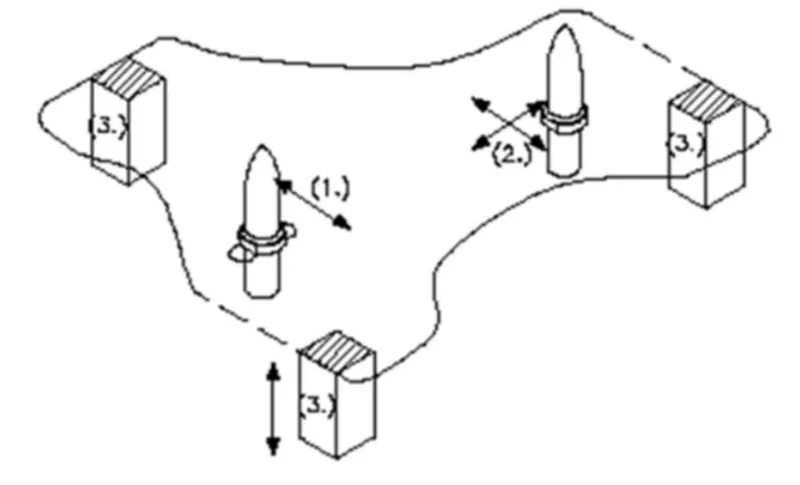
Any rectangular body many have three axis along x-axis, y-axis and z-axis. It can more along any of these axes or any of its movement can be released to these three axes. At the same time the body can also rotate about these axes too. So total degree of freedom of the body along which it can move is six. For processing the body it is required to restrain all the degree of freedom (DOF) by arranging suitable locating points and then clamping it in a fixed and required position. The basic principle used to locate the points is desirable below.
321 Principle:
The 3-2-1 principle states that the six locators are sufficient to restrict the required degree of freedom of any workpiece. In this, motion is restricted using clamps and locators. A three-pin base can restrict five motions and six pins restrict nine motions.
A workpiece will be completely confined when blanked against:
- 3 points in one plane: The “3” in 3-2-1 refers to 3 locators (passive fixture elements) on the primary locating/datum surface.
- 2 points in another plane: The “2” in 3-2-1 refers to 2 locators on the secondary locating/datum surface.
- 1 point in a third plane: The “1” in 3-2-1 refers to 1 locator on the tertiary locating/datum surface
1. Clamp Unit:
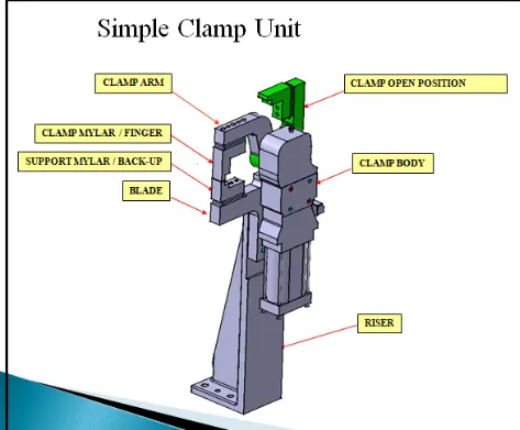
A clamp unit is a unit designed to clamp/hold the car panel with NC blocks/Mylars/rest by using a pneumatic cylinder. Clamp arm, finger, Rest/backup, Lblock, shims, riser, pneumatic cylinders are the typical parts of clamp unit.
Clamping force should be considered while designing a clamp unit. Usually clamp open position is 90. Fingers are attached to clamp Mylar.
In the Clamp unit shim to one side is more enough because it will restrict translation motion in an upward direction and downward direction only.
There is another type of clamp unit known as the swivel type. There is a pivot pin around which the clamp arm rotates.
2. Rest Unit:
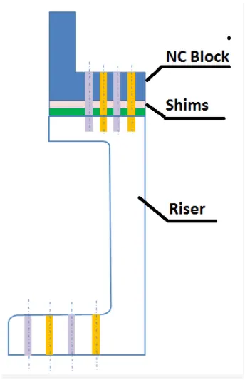
A rest unit is used to support the car panel, Also is resists clamping force of the finger with the help of rest mylars & thus clamp the car panel. Rest unit consists of rest mylars, shim packs, riser. Holding force should be considered while designing a rest unit. Mostly to avoid excess part, to reduce the weight & reduce the cost of the fixture the rest unit is combined with the clamp unit.
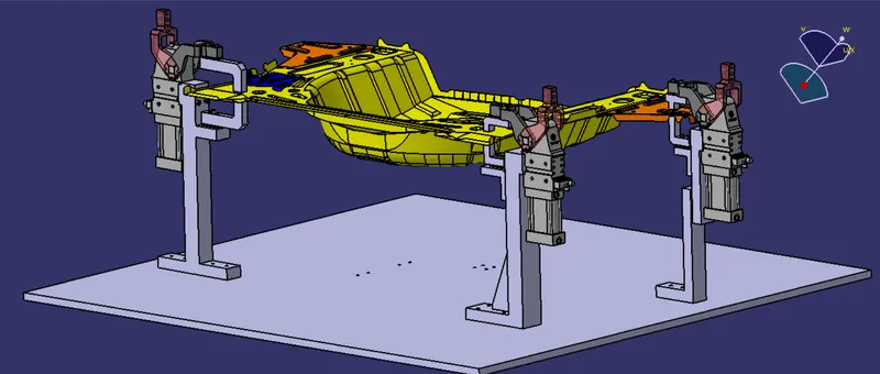
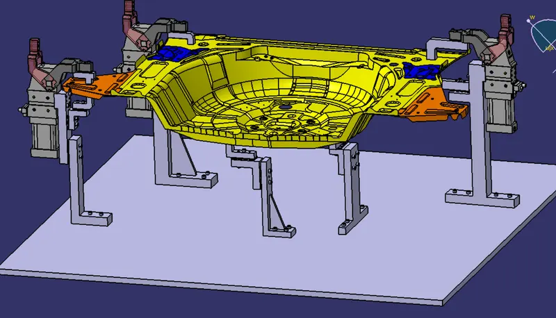
Below figure shows the combination of the clamps & rest unit which have been designed in this project by considering the basic principles of clamp & rest unit design.
Purpose of Rest Unit &Clamp Unit:
- The purpose of clamping tools is to securely hold the workpiece in position without obstructing the production process.
- It prevents distortion during the welding process and other processes.
- High clamping forces combined with compact dimensions are therefore the most important requirements for a clamping
tool. For this reason, clamps are also equipped with mechanical transmission gear units.
FORCE ACTING IN CLAMP & REST UNIT:
TO design a clamp unit we have considered some force that acts in the clamp for clamping purpose the force that act in clamp units are,
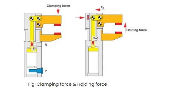
- Clamping force
- Holding force
Clamping force is not the same as holding force.
CLAMPING FORCE:
clamping force signifies the force applied to the workpiece by the drive mechanism via the clamp arm during the gripping or clamping operation.
Clamping force (Fs)= 48xS3 = force in newton HOLDING force
HOLDING FORCE:
holding force on the other hand denotes the maximum force, after locking the knee lever (over-center position) that can be applied by the workpiece on the workpiece on the gripper/ clamp arm without destroying the mechanism therefore particular attention the paid to the maximum holding force when for example during the production process (welding, bonding)there is a possibility of distortion of the component or if the clamp arm is used as a fixed stop.
If the holding force specified in the technical details is exceeded this will inevitably result in the destruction of the mechanism the clamp arm of the bearing position.
SELECTION OF PNEUMATIC CYLINDERS
- Single or Double acting
- Dimensional standards like ISO, VDMA, CETOP, AFNOR.
- Constructional details like – Piston rod, tie rod, square tube, Mickey mouse tube, rodless etc.
- Force to be exerted (Bore dia)
- Distance to be moved (stroke)
- Surrounding medium (special material of construction / type of seals)
- Air pressure available.
- Cushioned / Non cushioned.
- Ambient temperature for selection of seal material.
- Speed of actuation
- Position detection (Reed switch type)
- Mountings
- Stop tube length for long stroke cylinders.
SPECIFICATION OF PNEUMATIC CYLINDERS
- Cylinder thrust.
- Air consumption.
- Piston velocity.
- Type of mounting.
- Couplings
MATERIAL USED:
In general, the materials used for Mylars, Clamp arm, shims, shim block, blades & risers are:
- Mylars: UHMW, Nylon66, PP, Teflon (Polytetrafluroehylene (PTFE)). Materials of clamp block and rest block to be decided as per the A class panel or B class.
- Clamp Arm: SAE 4140 or SAE 1045.
- Shims / spacer: S.A.E. 1010 CRS FULL HARD, COLD ROLLED STRIP STEEL S.A.E. 1010 FULL HARD, S.A.E. 1020 HRS etc.
- shim block: STEEL ASTM A- 36, NM stainless, STEEL ASTM A-36, SS type 3030 or 304, etc.
- Blade: STEEL ASTM A-36, etc.
- Riser: STEEL ASTM A- 36, etc.
HARDNESS:
In general, the hardness of the materials for pins, pin retainers, shims, shim block, blades & risers are:
55 – 60 HRC to a depth of 0.5 -0.7mm after grinding.
SURFACE FINISH:
In general the hardness of material for Mylars, Clamp arm, shims, shims block, blades & risers are:
- Clamp arm: Munsell No.3.75YR6/14 safety orange
- shims/spacer: BLACK OXIDE FINISH (SURFACE TO BE FLATE PARALLEL TO WITHIN 0.015 T.I.R.
- Riser: SURFACES TO BE FLAT, PARRALLEL & PERPENDICULAR TO WITHIN 0.015 T.I.R.
UNIQUE PARTS OF A CLAMP & REST UNIT:
Finger: Finger is a NC block, which is mounted on the clamp arm of cylinder. And will press the car panel towards the rest, so it holds the car panel.
Design Methodology:
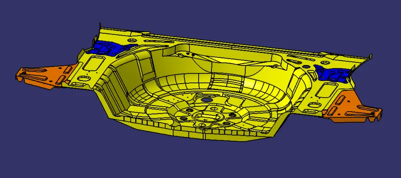
- First the neccesary file are downloaded such as car panel assembly.
- The standard pneumatic cylinders and Clamp arm which are the bought-out parts are downloaded from the Tunkers website and copied into the project.
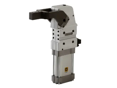
Standard clamp pnuematic Cylinder model : V_50_1_BR3_A40_T12_TUENKERS
- Clamp cylinders are bought out parts. Some of the manufactures are Tunkers, Zytran, Destaco, Festa, Steel smith
- Clamp cylinders are generally 40, 50, 63, & 80 bore capacity
- The Clamp mylars and rest mylars are designed and positioned in such a way that the movement of the car panel is restricted. The Clamp Mylars are attached to the clamp arm for the opening and closing movement.
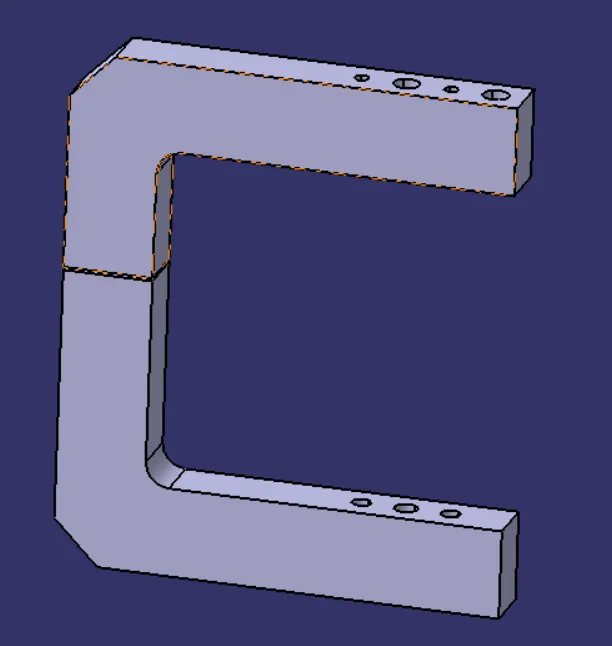
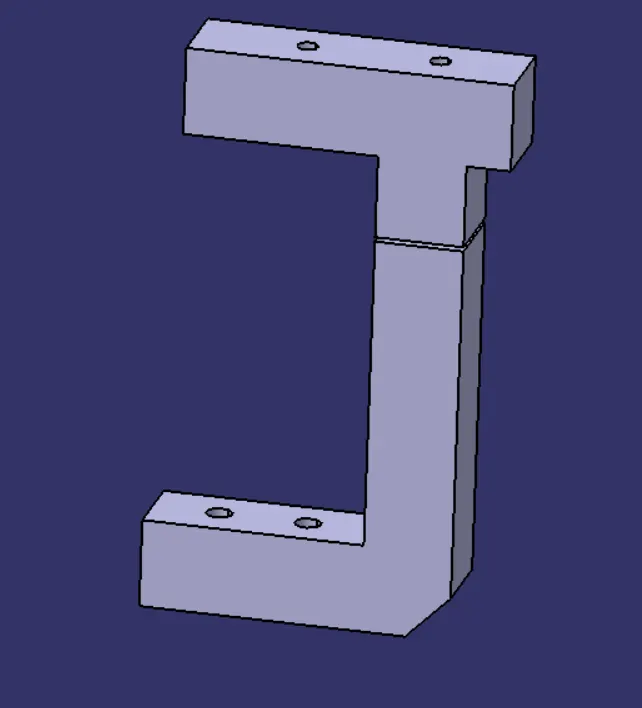
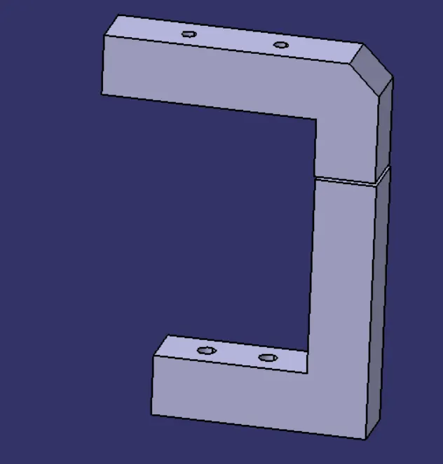
A gap between the rest and the clamp mylars si around 1mm considering the thickness of the car panel.
- Riser is a part on which all the parts are mounted and it is mounted on the base plate of the fixture. The risers are designed such that all the above parts are mounted on them. The risers are mounted to the base of the fixture
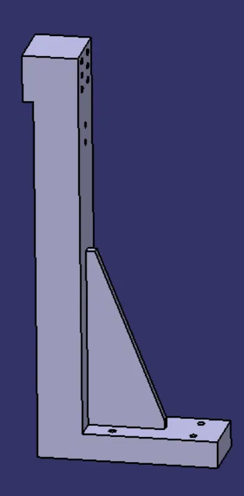
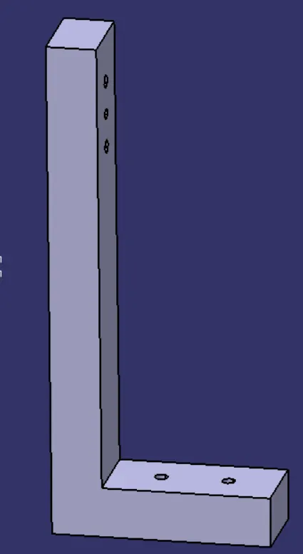
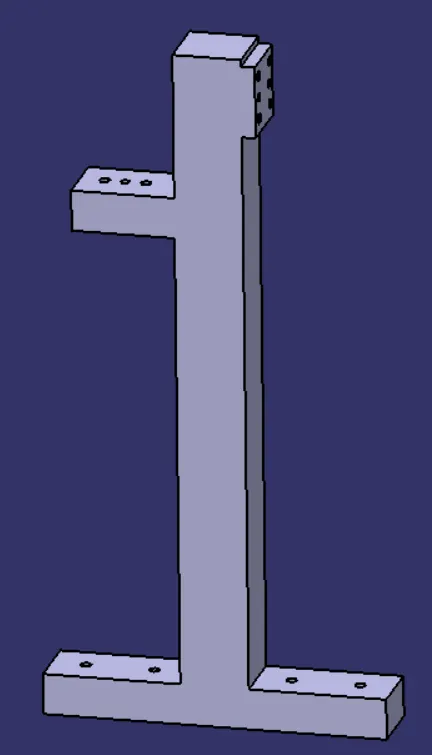
Now since there is change in the riser designs in all the above three, L blocks are attached to the riser in order to support the rest mylar.
Shims are designed as per the required dimension witn constant thickness of 5mm.

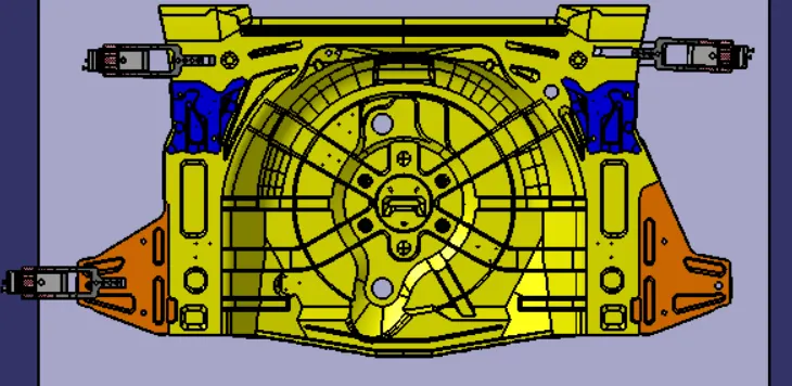
Now all the parts are assembly and the clamp units are positioned to hold the car panel as shown below. The coloured part of the arm represents the complete open position of the clamp arm.
- Next we have to design the Rest unit aasembly in the similar way the clamp unit is designed.
- The parts of the rest units are as follows
- Mylar
- Blade
- Risers
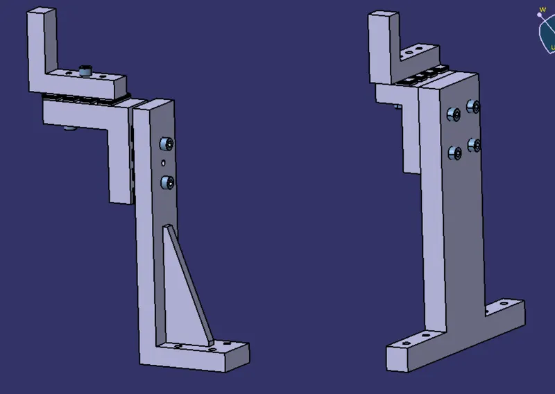
The rest mylars are positioned below the panel in order to support them. The blades are designed to support the rest mylar with the riser. 5mm Shims are added between the Rest mylar and the riser. The riser is designed in such a way that it supports the rest mylar.
The below images show 2 diffent types of Rest units with different blades and risers.
Finally the all the risers are attached to the base plate with the help of bolts of appropriate size and dimensions (~8mm dia - threaded).
CONCLUSION:
Hence as per objective, the 3 different types of clamp unit & 3 different types of rest unit by considering holding force has been designed. Also the materials, surface finish & heat treatment used in the parts of clamp unit, purpose of clamp unit, (3-2-14 principle) achieved by clamping, PLP points (Principle Locating Points) are explanied.