Week - 5 - Modelling Spotwelds
REPORT 5
AIM
To model spot welds using beam and solid elements separately in a systematic manner for the given assembly of parts and to run a crash test to required output data given below.
INPUT
- 3-7 spots welds should be used along the line specified in the assignment
- *MAT SPOTWELD should be used for both solid & beam elements
- Material card steel can be used for both solid and beam elements
OUTPUT
- The axial force & shear force between the beam and solid should be compared separately.
- The failure should occur at half of the termination time.
- Input. k file and output files (d3plot,glstat,sleout,rcforc)
- Animation of the final simulation
- The cross-sectional force generated in the middle of the crash box (along its length).
- Acceleration plot of a node in the middle of the crash box (along its length)
- Maximum directional stress and strain along the length of the crash box (X strain, Y strain, etc)
- Plot of all energies (total,internal,kinetic,hourglass,sliding)
- Compare the accelerations and stress/strain plots of the crash boxes.
THEORY OF SPOTWELD
Spot weld is known as the resistance welding process. Spot welds are made by applying pressure with a pair of copper electrodes where the copper conducts the electric current and it passes through the sheet metals. Initially, the sheet metal made up of steel resists the current flow, since steel is the poor conductor of electricity, and at some time, by giving a contact pressure the sheet metals allow the flow of electric current and as a result, the heat is generated and the metal fuses together.
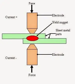
Fig , represents the working of spot weld
PROCEDURE
- Initially, open the Spotweld-assignment.k file in the LS -prepost.
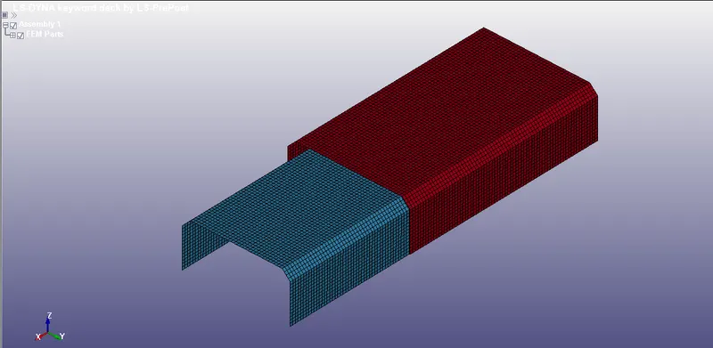
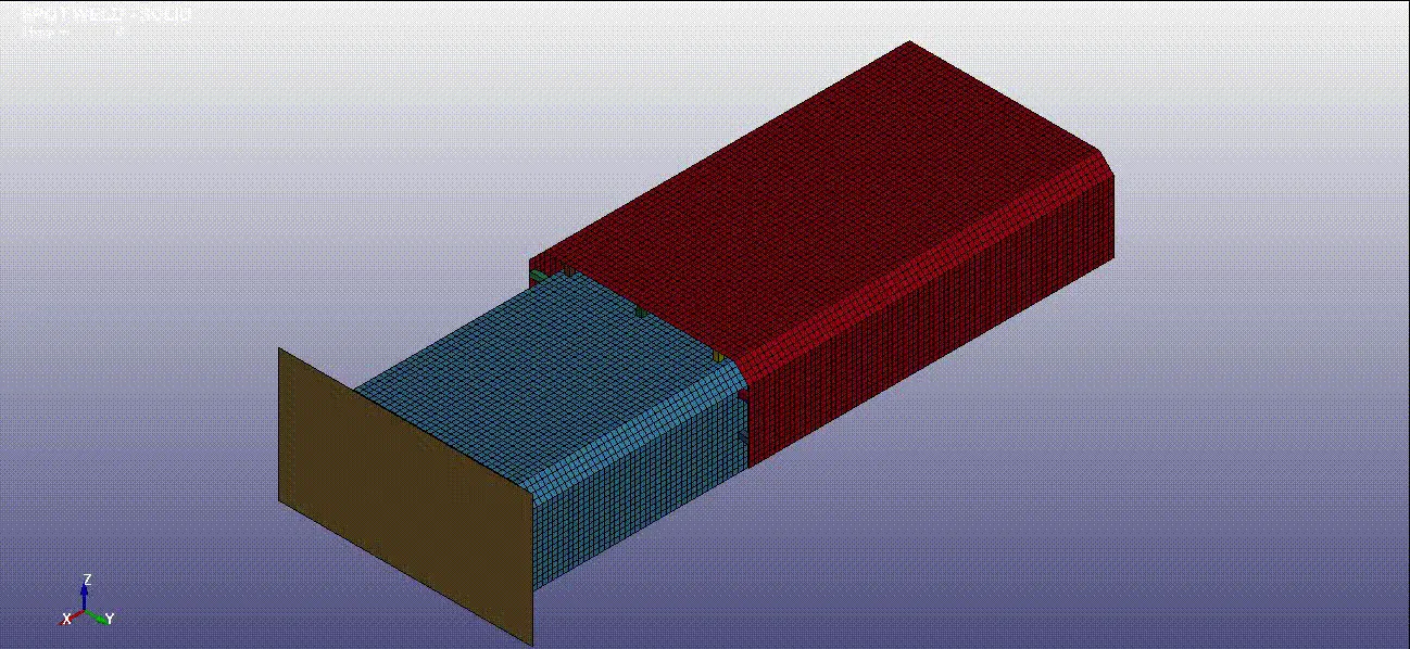
Fig, represents the sheet metal parts with shell elements.
- After, importing is done the geometry is orientated in a correct position in order to model the spot weld.
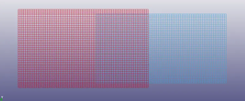
Fig, represents the top view of the sheet metal parts for spot welding
- In order to create a spot weld using beam elements, go to the element & mesh > element editing >create>element type> select beam>pick nodes N1 & N2 > give PID and then create a beam weld.
- once, the beam weld is created, create 3-7 spot welds along the line using the element editing option and provide different PID for each beam element.
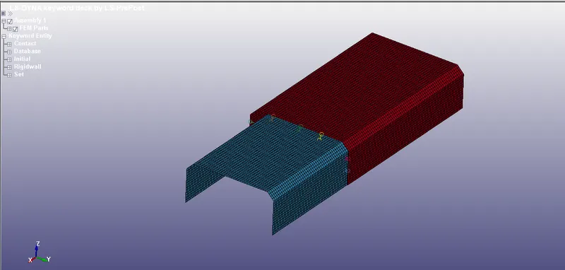
Fig, represents the creation of spot weld using beam elements along the line by keeping it in isometric view
- Then, we need to check PID for every beam element that has been created, for that go the Model & part >keyword manager > part.
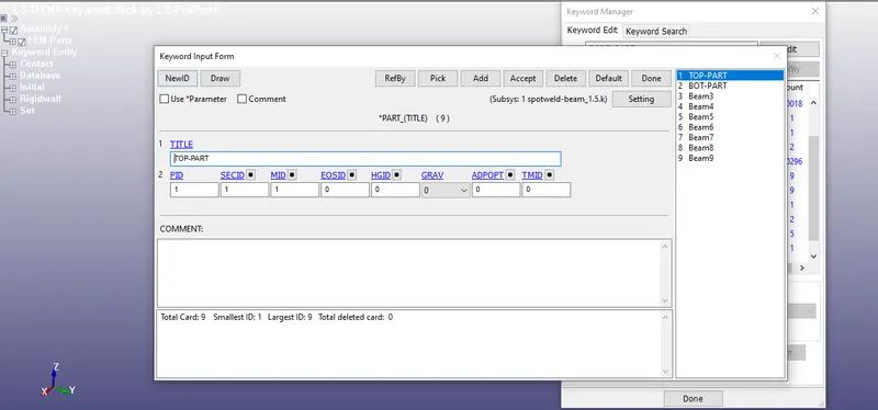
Fig, represents the PID defined for every beam element that has been created.
- In order to define a part, we need a section ID and material ID in order to define a part.
- Go to Model & part >keyword manager > section>beam and then create a beam section.
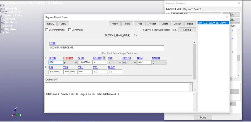
Fig, represents the beam section defined
- From, the figure it is observed that ELFORM 9 is used to define a beam element since we use *MAT spotweld as a material and the *MAT spot weld can take only the beam element with ELFORM9 and so the ELFORM for modelling a beam element is defined here.
- Once, the SECID , is defined now we can define a material Id and for that go to model&part>keyword manager >all>MAT>Spotweld.
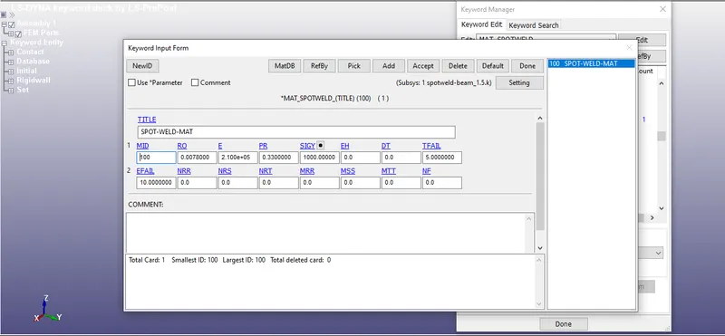
Fig , represents * MAT SPOT WELD with different Material properties defined
- The reason, why we use *MAT spot weld as a Material card, it gives you information about the failure criteria and we can validate the failure using MAT spot weld.
- In this case, TFAIL (a time-based failure ) is given to fail the beam weld at 5 ms and along with the material properties of steel such as density, Young's modulus, Poisson ratio, and yield stress has been assigned.
Density = 0.00783 gm / mm^3
poisson ratio = 0.33
Young's Modulus = 2.1*10^5 Mpa
Yeild strength =1000 Mpa
TFAIL = 5 ms
- Then we create a shell section for the sheet metal and the shell section can be created using model >keyword manager>section>select shell section.
- Now, thickness 1.5mm and Element formulation =16, and SECID is provided for the shell section.
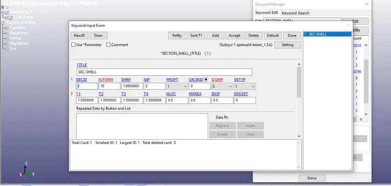
Fig, represents the section defined for the shell element with ELFORM16
- The reason, why the ELFORM 16 has been assigned is, the MAT spot weld card can only take the shell elements with ELFORM 16
- Once, the shell section has been defined, we can define the material for the shell element.
- Once, the SECID , is defined now we can define a material Id for the shell element, and for that go to model&part>keyword manager >all>MAT>Elastic
- Here, the elastic material card is used and the material properties of steel is assigned to it.
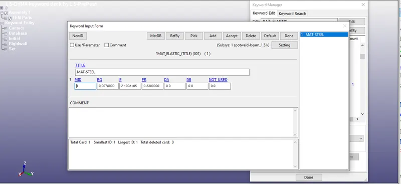
Fig, represents the assignment of material properties (steel) using *MAT Elastic
- Once, the section and material properties for the beam and shell element are created, now we go to the part and assign the section and material properties for the beam and shell element.
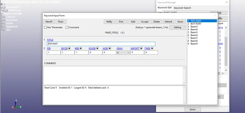
Fig, represents the assignment of Material and section properties for beam element and the shell part
- Here, we create one beam section and one *MAT-SPOTWELD and we assign to all the beam welds which are present in the part, and this way a part is been created for the beam spot welds.
- In a similar fashion, one shell section and one Elastic material and we assign to the shell parts which are present in the part, and this way a part is been created for the shell elements.
- Then, we create a rigid wall by using create entity option and with 1n +NL option.
- The rigid wall is created and translated at 15 mm away from the crash box.
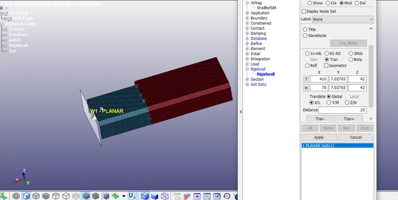
Fig, shows the creation of a rigid wall with a 1+NL option.
- The Normal should be in the opposite direction to the velocity of the sheet metal parts, such that it should offer a reaction force during the impact and avoid the penetration of the sheet metal part into the rigid wall.
- If the Normal and velocity of the sheet metal are in the same direction, penetration of the sheet metal onto the rigid wall would occur.
- Then, the next step is to create an initial velocity.
- Before doing that, in the create entity option > SET-NODE, selected the entire area of the nodes in the shell parts and create an NSET ( a node-set). The purpose of creating NSET is to define the initial velocity for the shell parts.
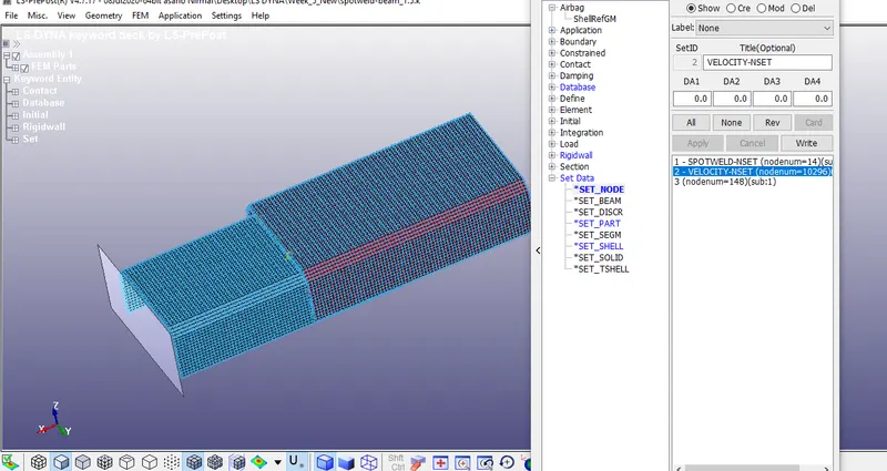
Fig, shows the creation of NODE SET for assigning the initial velocity for the shell parts.
- once, the node-set for the velocity is created, the velocity of 50kmph(13.889 mm/ms) is assigned by model & part >keyword manager>initial> velocity is defined.
- Now, the initial velocity is assigned in the initial velocity card.
- The velocity of 13.889 mm/ms is assigned in the x-direction.
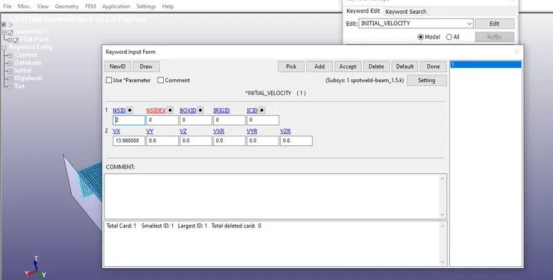
Fig, represents the velocity assigned in the x-direction
- The cross-section force can be obtained by using create entity option and in that the node-set and shell set is created by picking the areas of nodes using *SET_NODE and picking the area of shell element by *SET_SHELL respectively.
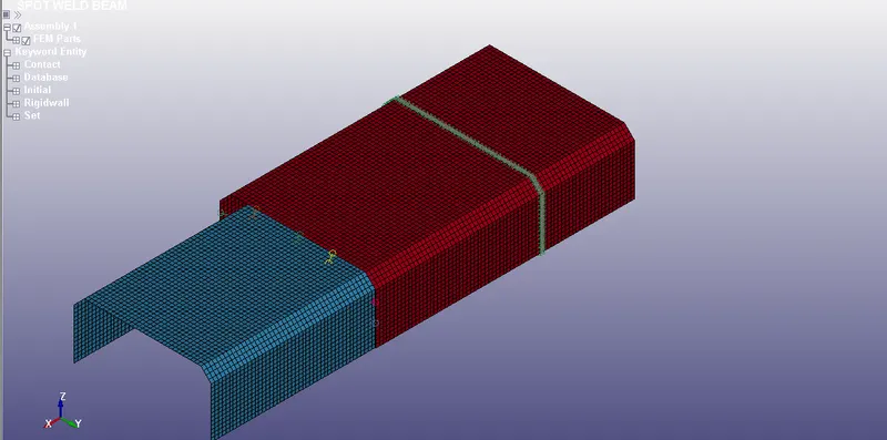
Fig, represents the cross-section defined by picking nodes and elements
- Then, we need to create a contact by using Model & part>keyword manager > contact > *CONTACT_TIED_SHELL_EDGE_TO_SURFACE.
- Before doing, that we need to define a slave and Master, here the slave is defined as beam and Master is defined as a shell part.
- In order to define them, go to create entity > *SET_NODE>pick all the nodes of the beam element and create an NSET containing all the spotwelds ( it means the spot welds have been created as a set).
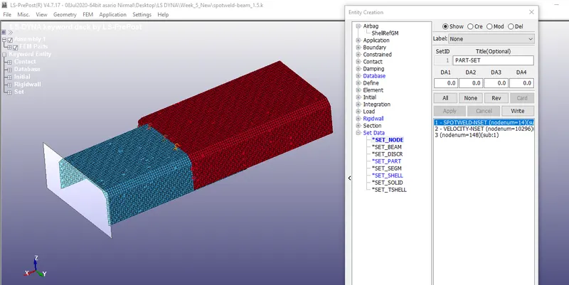
Fig, represents the creation of NODE SET for the spot welds
- Then, go to go to create entity > *SET_PART>select the two shell parts by using the part option and create a part set.
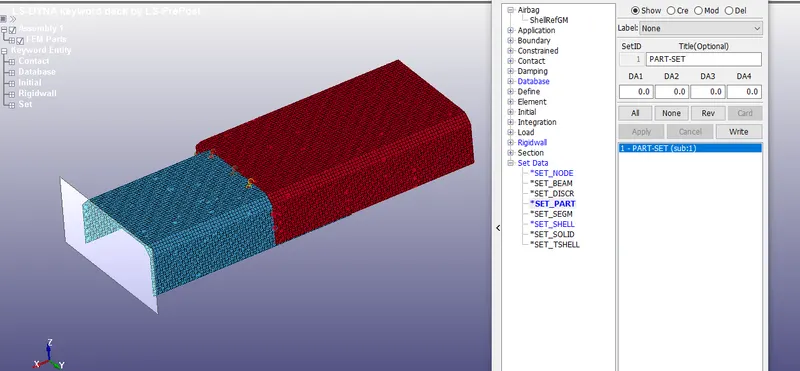
Fig, represents the creation PART SET for the SHELL PARTS
- Now, it's easier to define a slave and Master.
- In the *CONTACT_TIED_SHELL_EDGE_TO_SURFACE
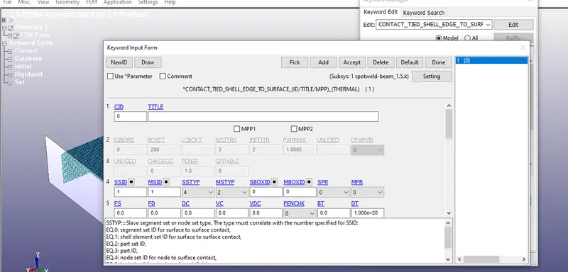
Fig, represents the assignment of MSID, SSID, SSTYP & to MSTYP to the *CONTACT_TIED_SHELL_EDGE_TO_SURFACE
- Here, the Part set ID of the shell part is assigned to MSID and the node-set ID of spotweld is assigned to SSID (slave set ID)
- Also, we need to assure that during impact both the shell parts do not come into contact and penetrate each other, and in order to avoid that the automatic single surface contact is used.
- In automatic single surface contact, the parts will act both master and slave and so we can either we can define one and contact algorithms in LS-DYNA will detect the master and slave automatically.
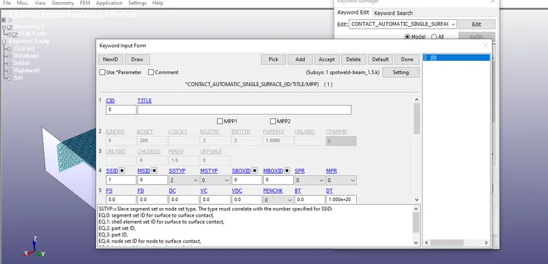
Fig, represents the assignment of SSTYP & SSID to the *contact_Automatic_SINGLE_SURFACE
- In the automatic single surface, penetration is avoided by considering the parts as a single surface.
MODELLING OF SOLID ELEMENTS
- The same technique which is used for modelling of beam elements is used for modelling of solid elements, only the section and the contact of the solid is been changed.
- Here the section we used to define is solid elements and the contact spot weld is used for defining the contacts and the procedure remains the same.
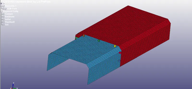
Fig, represents the creation of spot weld using Solid elements along the line by keeping it in isometric view
- Go to Model & part >keyword manager > section>solid and then create a solid section.
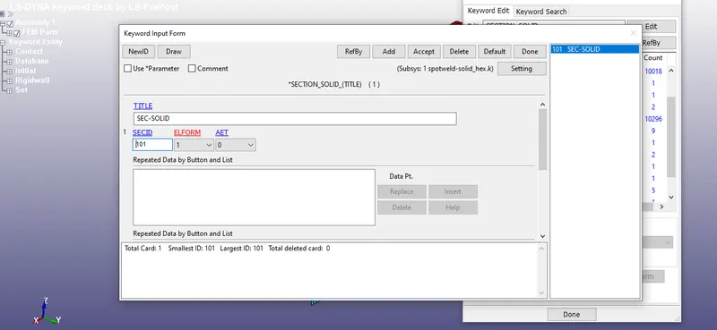
Fig, represents the defining the section for solid element with ELFORM 1
- From, the figure it is observed that ELFORM 1 is used to define a solid element since we use *MAT spotweld as a material and the *MAT spot weld can take only the solid element with ELFORM1 and so the ELFORM 1 used for modelling a solid element is defined.
- The material properties are same and *MAT_SPOTWELD is used for both the cases.
CONTACT SPOTWELD
- create a contact by using Model & part>keyword manager > contact > *CONTACT_SPOTWELD
- Here, we define a contact spot weld card for defining the contacts for solid elements and to the shell parts
- Here, the Part set ID of the shell part is assigned to MSID and the node-set ID of solid elements is assigned to SSID (slave set ID)
- Also, we need to assure that during impact both the shell parts do not come into contact and penetrate each other, and in order to avoid that the automatic single surface contact is used.
- In automatic single surface contact, the parts will act both master and slave and so we can either we can define one and contact algorithms in LS-DYNA will detect the master and slave automatically.
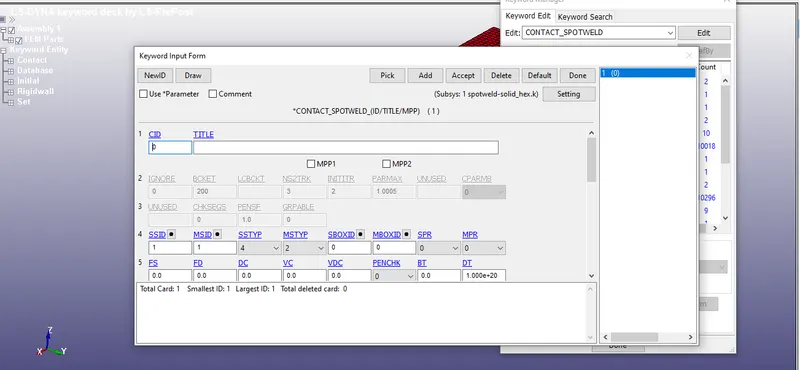
Fig, represents the assignment of SSTYP, MSTYP, MSID & SSID to the contact spot weld.
- Here we link, the MSID to the part set ID that we created and we link the SSID to the node-set ID that we created for the solid elements.
- Finally, in the control card, termination time has been provided and here the termination time will be twice the time of TFAIL time and the purpose why we have provided the extra terimination is, that the failure of the weld should happen at half of its time and to know about the bouncing back of the sheet metal parts after the impact, the extra time is been provided.
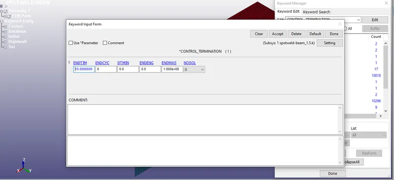
Fig, represents the end time defined for the sheet metal parts
Now, the following output files are obtained by *DATABASE card and a time step of 0.5 ms is assigned to each output card
DATABASE_BINARY_D3PLOT = used for the animation process
DATABASE_ASCII_NODOUT= used for finding nodal motions
DATABASE_ASCII_GLSTAT= used to find global statistics and energies
DATABASE_ASCII_RCFORC= used to find resultant contact interface forces
DATABASE_ASCII_MATSUM=used for find material energies
DATABASE_ASCII_SLEOUT = used to find contact interface energies
DATABASE _ASCII_SECFORC = Used to cross-section forces data .
Finally, the .k file for both solid and beam elements are saved and the file is opened in LS RUN and the file is solved using LS RUN.
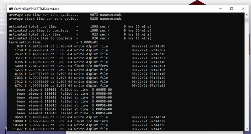
Fig, represents the Normal termination done by LS -RUN
OUTPUT RESULTS
ANIMATION OF THE FINAL SIMULATION
ANIMATION FOR THE BEAM ELEMENT
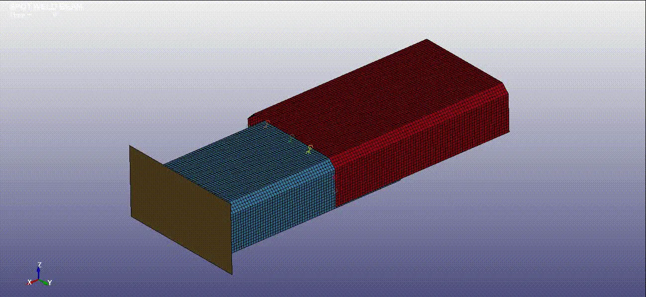
ANIMATION OF THE SOLID ELEMENT
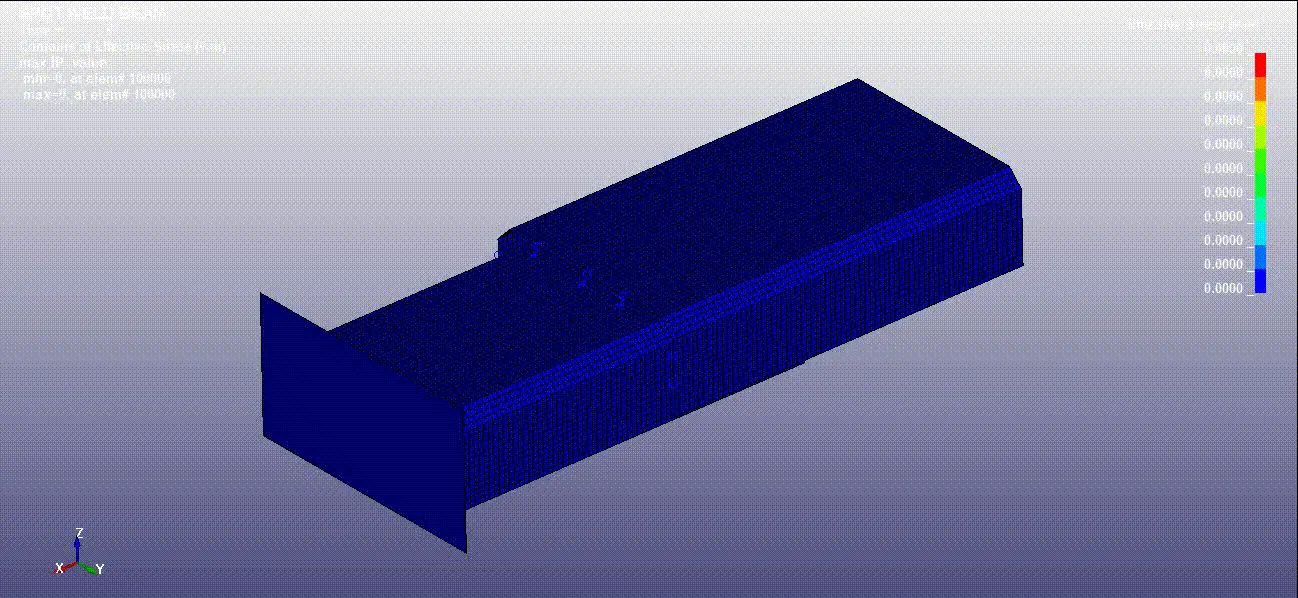
VON-MISES STRESS OF BEAM
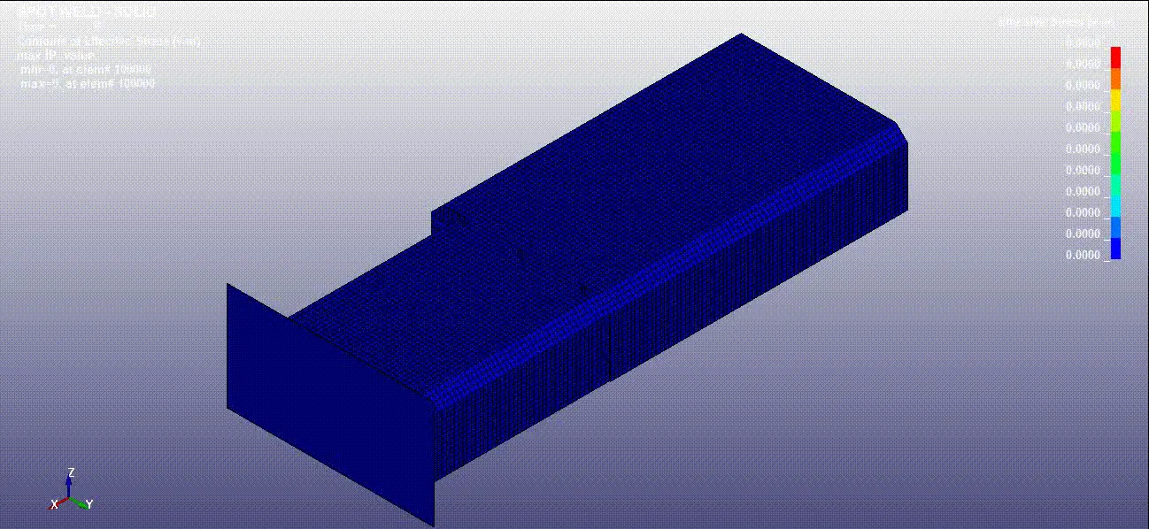
VON-MISES STRESS OF SOLID ELEMENT
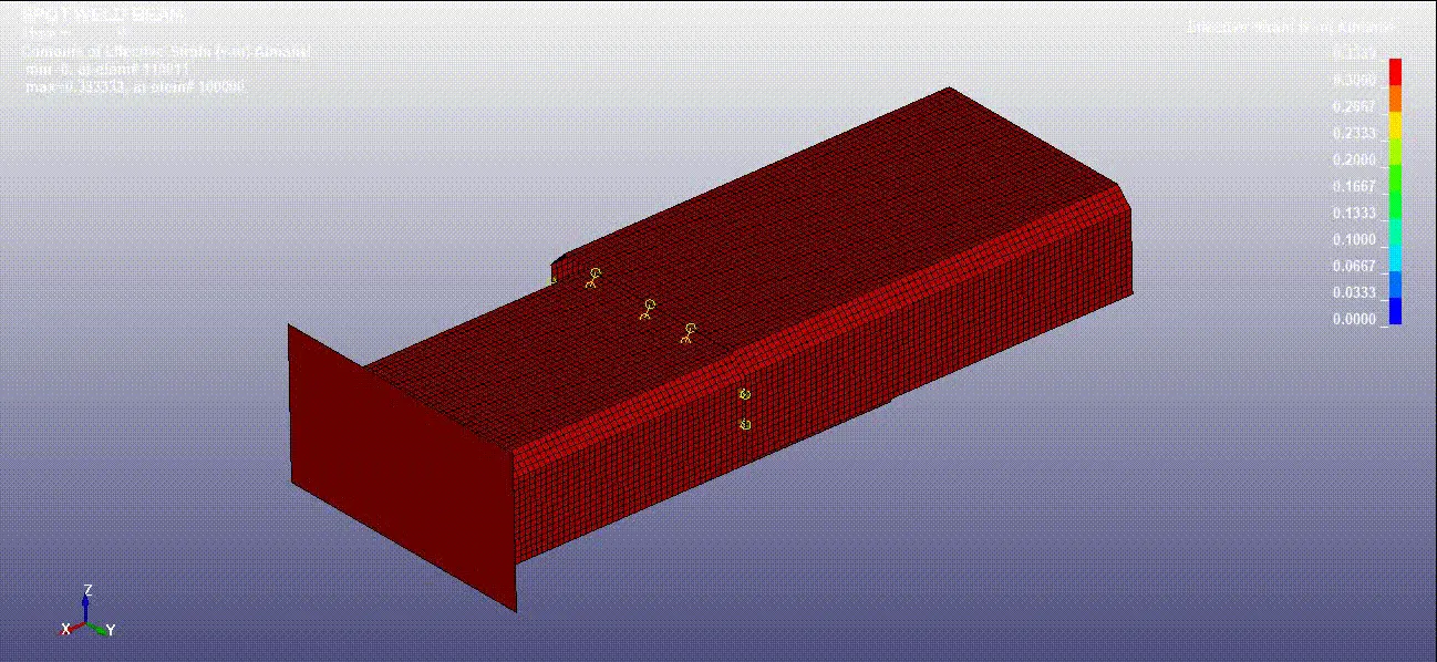
VON STRAIN OF BEAM
VON STRAIN OF SOLID ELEMENT
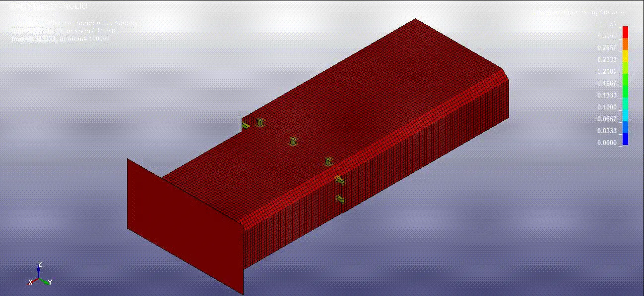
AXIAL FORCE FOR BEAM AND SOLID SPOT WELDS
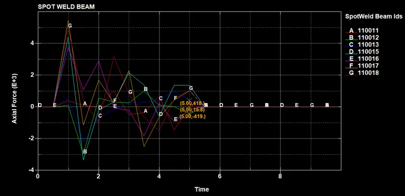
Fig(a), represents the spot weld beams failure due to axial force
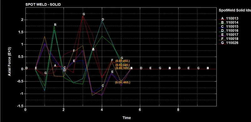
Fig(b), represents the spot weld solid element failure due to axial force
From, fig (a) & fig (b), it is observed that the beam spots weld takes comparatively larger axial force overall when compared to the solid spot welds. This is because the cross-section area of the beam spots welds are comparatively smaller than solid elements. Additionally, it is also observed that at the time of failure the spot welds take a lighter or smaller axial force to fail suddenly and on the other hand the solid spot welds take the larger axial force to fail and this due to the differences in cross-sectional area between the beam and spot welds. As we know the larger the cross-section ability to deform is very less and it takes even larger force for failing. This is the reason why the solid spot welds take larger axial force before failure. Additionally, it has been observed that the failure happens exactly at 5.5 ms since at the (TFAIL=5ms), the solver computes all the axial forces of the spot welds at TFAIL time and it shows the failure results at the next time step which is 5.5ms. In general, the spot welds failure is due to axial forces since the spot welds are weaker in axial forces and stronger in the shear.
SHEAR FORCE OF BEAM AND SOLID SPOT WELDS
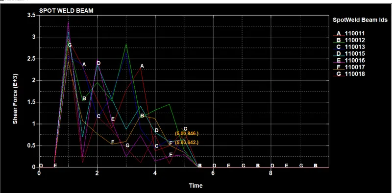
Fig(a), represents the shear force diagram for the Spot weld beam element
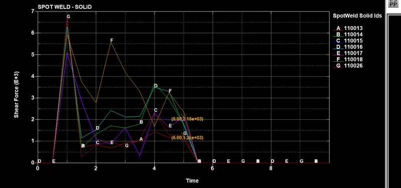
Fig(b), represents the shear force diagram for the Spot weld solid element
From, fig(a) & fig (b) it is evident that the shear force of the spot weld beam elements takes lesser shear force to fail and on the other hand, the spot weld of solid elements takes larger shear force to fail, this is mainly due to the cross-sectional area differences between the beam and solid elements.Also, it is evident that, the solver computed the TFAIL result at the end of 5.5ms since the shear forces failure are computed at 5 ms and its failure results are shown at the next time step.
CROSS-SECTIONAL FORCE IN THE MIDDLE OF THE SHEET METAL PARTS
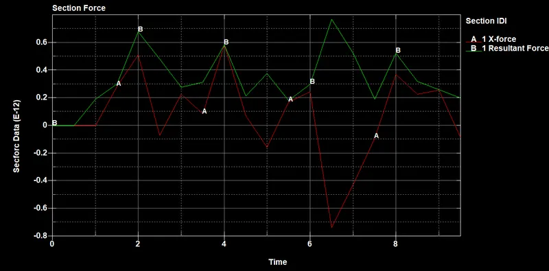
Fig(a), represents the cross-sectional force generated for the spot weld beam along with X and resultant force
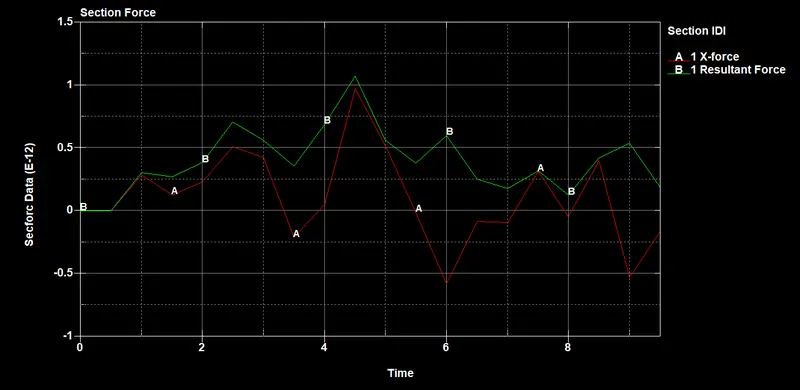
Fig(b), represents the cross-sectional force generated for the spot weld solid along with X and resultant force.
From, figure (a) and (b), it is observed that the cross-section forces of the spot weld with solid elements is comparatively larger since the solid elements have a higher mass and we know that increase of mass increases the force (F=ma) and so solid elements cross-sectional forces are higher when compared to the beam elements which has a lower mass.
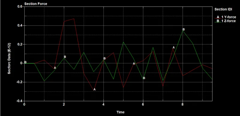
Fig(a), represents the cross-sectional force generated for the spot weld beam along with Y and Z force
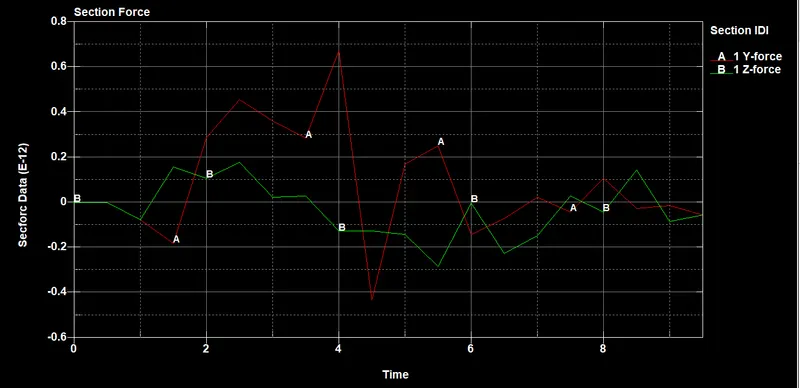
Fig(b), represents the cross-sectional force generated for the spot weld solid along with Y and Z force
From, the figure (a) & (b)it has been observed that the spot weld solid has higher cross-sectional forces in the Y & Z direction when compared with the spot weld beam. In both cases, the spot welds have lower cross-sectional forces in the Y & Z since the impact is done only in the x-direction.
ACCELERATION PLOT IN THE MIDDLE OF THE SHEET METAL PARTS
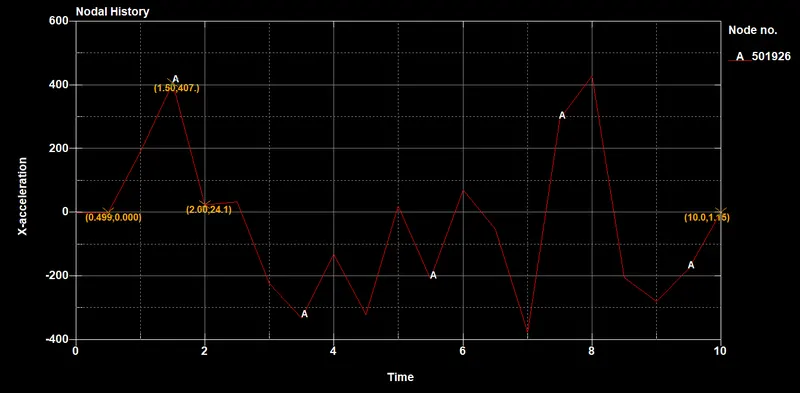
Fig(a), represents the x acceleration plot for the spot weld with beam elements
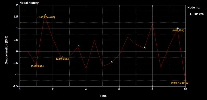
Fig(b), represents the x acceleration plot for the spot weld with solid elements
From, fig (a) & (b) it is observed that we can see the deacceleration occurs for the spot weld with solid elements during the impact at the time interval of 0.5 ms and it is due to the increase of momentum of sheet metal parts which has solid elements and we know that increases of mass increase the momentum (P=mv)rapidly and due to the sudden impact, the sheet metal parts with solid element acceleration has come down and during the rebounce the acceleration gains again and drops down until the end of the termination time. Also, it has been noted that the acceleration for the spot weld with beam element is not constant, it has undergone some acceleration and deceleration, until the end of the termination time.
MAXIMUM DIRECTIONAL STRESS
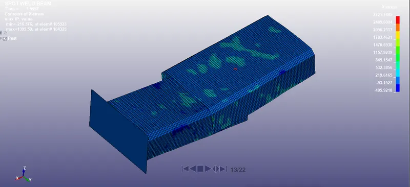
Fig(a) , represents the max-directional x stress for the spot weld beam element
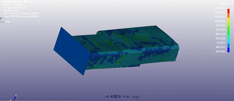
Fig(b), represents the max-directional x stress for the spot weld solid element
From, fig (a) & (b) it is observed that the maximum directional x stress in the spot weld beam increases due to its reduced cross-sectional area and whereas in the spot weld solid element the stress values are reduced due to the increased cross-sectional area. Change of cross-sectional area plays an important role in the increase or decrease of stress values.
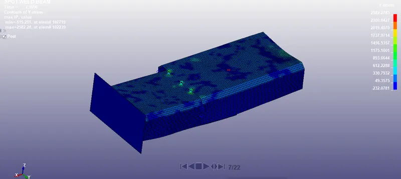
Fig(C), represents the max-directional Y stress for the spot weld beam element
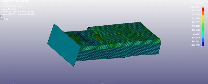
Fig(D), represents the max-directional Y stress for the spot weld solid element
From, fig (c) & (d) it is observed that the maximum directional Y stress in the spot weld beam increases due to its reduced cross-sectional area and whereas in the spot weld solid element the stress values are reduced due to the increased cross-sectional area. Change of cross-sectional area plays an important role in the increase or decrease of stress values.
MAX DIRECTIONAL STRAIN (X & Y)
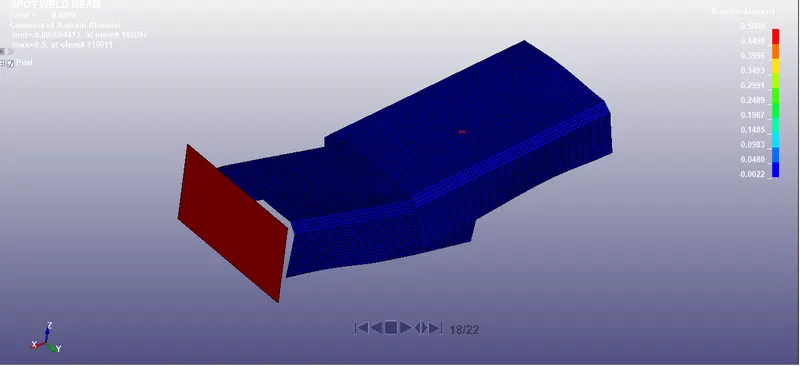
Fig(a), represents the Maximum direction directional x strain for spot weld beam
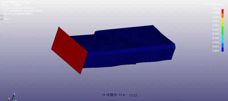
Fig(b), represents the Maximum direction directional x strain for spot weld solid
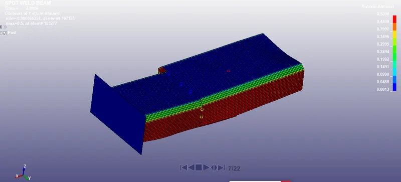
Fig(c), represents the Maximum direction directional Y strain for spot weld beam
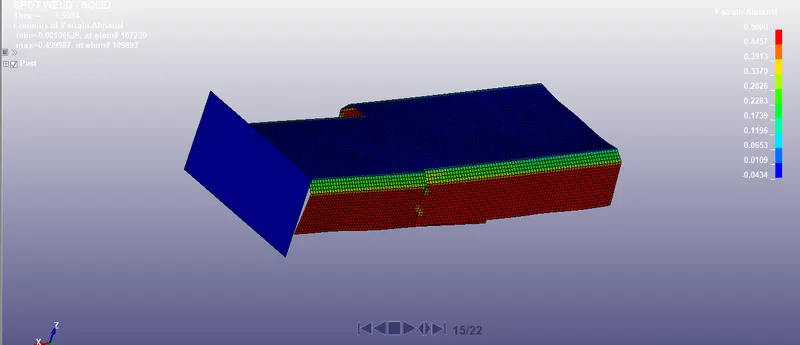
Fig(D), represents the Maximum direction directional Y strain for spot weld solid
From, figures (a) & (b), it is observed that the x strain is very high for the spot weld beam since it has less cross-sectional and then the tendency to strain is very high when we compare with the spot weld solid element. The increased cross-sectional area of the spot weld solid element helps the beam element to strain less when compared with beam elements.
similarly, from the figures (c) & (d), it is observed that the Y strain is very high for the spot weld beam since it has less cross-sectional and then the tendency to strain is very high when we compare with the spot weld solid element.
PLOT OF ALL ENERGIES
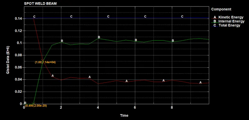
Fig(a), represents the GLSTAT DATA PLOT for the Beam spot weld
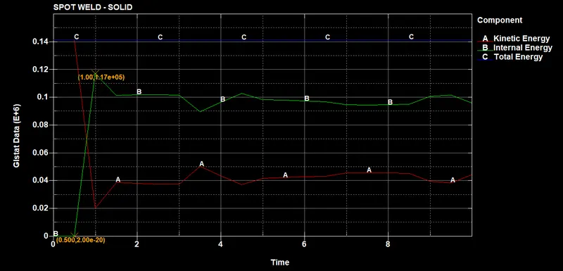
Fig(b), represents the GLSTAT DATA PLOT for the solid spot weld
From, fig (a) & (b), it is observed that as the sheet metal approaches the rigid wall with a velocity of 13.889 mm/ms, it makes an impact on the rigid wall and as we that the kinetic energy of the sheet metal parts drops down suddenly due to the impact and we can see the increase in kinetic energy and this is due to the law of conservation of energy. During the impact kinetic energy gets converted into internal energy and we can see that the total energy remains constant in the system. Additionally, it has been observed that the internal energies of sheet metal parts containing the solid spot welds are higher than internal energy since they have a larger mass when compared to the sheet metal containing beam spot welds.
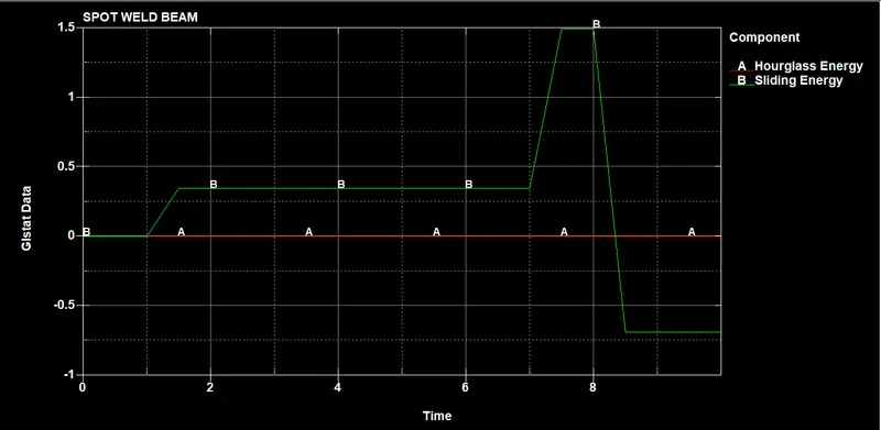
Fig(a), represents the GLSTAT DATA containing hourglass energy and sliding energy for the spot weld beam
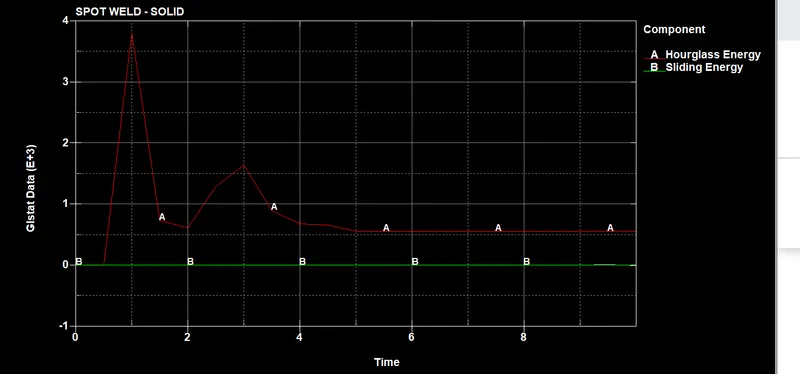
Fig(b), represents the GLSTAT DATA containing hourglass energy and sliding energy for the spot weld solid
From, figures (a) & (b), it is observed that the sliding energy is increased for the spot weld beam since the spot weld beams stiffness are comparatively lower and on the other hand the sliding energies are comparatively small in the case of spotweld solid elements. The hourglass energies are small in the case of spot weld beam elements and on the other hand the there is slight hourglass energy in the case of spot weld solid elements.
VON-MISES STRESS
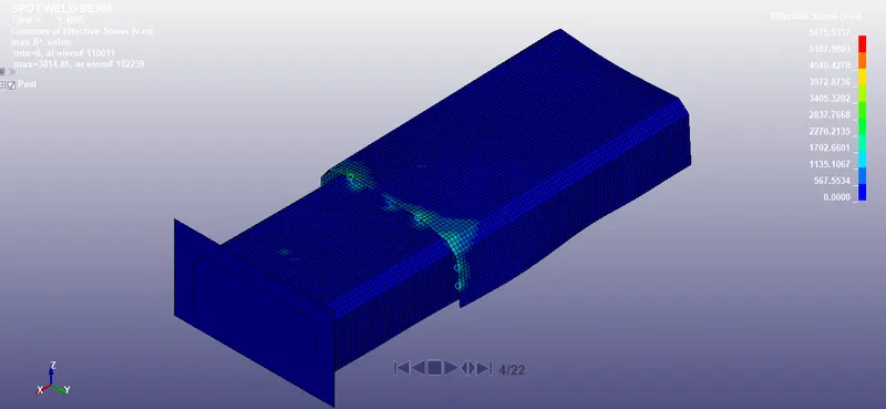
Fig (a), represents the Von-mises stress for spot weld beam
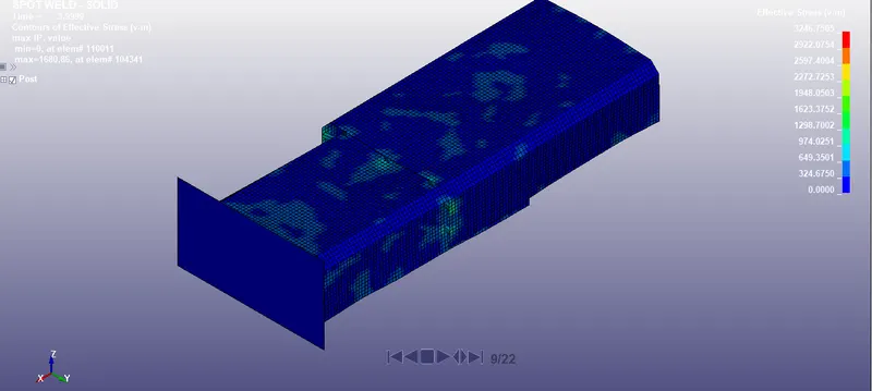
Fig (b), represents the Von-mises stress for spot weld solid
From Fig (a) & (b), it is observed that the von-mises stress for the spot weld beam element is been increased and it is due to the cross-sectional area is less and on the other hand, it has been observed that the spot weld solid has low stress since the solid spot weld has a large cross-sectional area and it can resist more stress or the impact forces so the solid spot welds have lower stress. The maximum stress found in the beam spot welds is found to be 5675 Mpa and for the solid spot weld is found to be 3246 Mpa.
324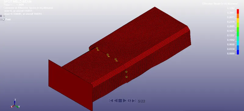
Fig (a), represents the effective strain (V-m ) for beam spot weld
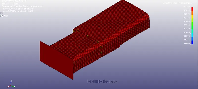
Fig (b), represents the effective strain (V-m ) for solid spot weld
From, Fig (a) & (b), it is observed that the effective strain of solid spot weld are slightly larger than the beam spot welds and in both cases strains we observe that there is only a slight strain difference for both the welds.
CONCLUSION
- The spots are modeled using beam and solid elements separately using the same component.
- All the inputs for modeling the beam and solid spot welds are defined systematically in the right manner to run the simulation.
- The beam and solid welds are made to fail exactly at half of the termination time.
- The axial and shear forces of the beam and solid spot welds are compared separately.
- The output data files are requested as given in the challenge.
- All the output plots and energy plots are compared to both solid & beam spots welds successfully
- The requires output data files are requested and compared successfully.