Week 5 Challenge : Surface wrap on Automotive Assembly
Objective:
- In the models that have been provided to us, we need to look for errors in the geometry and get rid of any surfaces that won't be used for surface wrapping.
- Following the completion of the geometry cleanup, we will combine all three models.
- After that, the surface wrap operation for the merged model is the last step that needs to be completed.
ANSA:
The automotive industry makes extensive use of the computer-aided engineering tool known as ANSA for finite element analysis and computational fluid dynamics (CFD) analysis. BETA CAE Systems is the company that created it. A number of BETA CAE Systems subsidiaries and business agents work together to disseminate the software all over the world.
ANSA ensures that the connection between the CAD geometry and the FE mesh remains intact. This indicates that the FE meshes are superior representations of the geometric parents to which they belong. Additionally, it is simple to maintain and update any changes in the geometry by merely rewriting the updated region rather than starting from scratch to recreate the FE. This makes it straightforward to do so.
It includes many unique algorithms for meshing that are appropriate for computational fluid dynamics (CFD) simulations as well as structural models. Automatic net generation for structural analysis was the original meaning of the acronym ANSA, but the software has rapidly expanded beyond that scope. TOPO MESH, VMESH, DECK-SOLVER, MORPH, and HBLOCK are the names of the many operations that can be accomplished with the help of ANSA's broadly six menus.
Surface Wraping:
The component is meshed using surface wrap as the technique. If the geometry is complex and it's difficult to smooth out the topography and create a single volume, we can use a technique called surface wrap to create a mesh that does just that. Depending on the data that is provided, it will either create an inside or an outside wrap. In our model, we begin by wrapping the object from the outside and do not concern ourselves with the inner surfaces. In order to obtain the precise surface wrap output, it is necessary for us to get rid of any unnecessary surfaces that we don't want and to close any open surfaces that are still visible. On this kind of model, we perform an outerflow analysis when air flows through grills and then over the engine. This allows us to determine how efficient the air flow is over the engine and the amount of convective heat transfer that occurs from the engine to the air. Because of this, we require mesh on the exterior, and the best kind of mesh for this job is surface wrap mesh. If you have a complicated model like this one, then you should use surface mesh for each individual component. If you are attempting to make a single volume and define volume and delete all those, then you should do surface wrap instead of going through such a lengthy and complicated process. This will allow us to get directly to a common volume for all three components after we have merged and done surface wrap.
ANSA contains a variety of modules of the following types:
TOPO is an abbreviation that stands for "Set of Tools for Optimizing and Polishing Geometry."
Tools that may create Surface Mesh or 2D Mesh are referred to as MESH.
VOLUME MESH is used to generate a solid or three-dimensional mesh.
SOLVER DECKS are tools that are constructed on the back of several solvers, such as ABAQUS, RADIOSS, and ANSYS, amongst others.
MORPH is an advanced tool that allows for more precise capturing of geometry during the meshing process.
Method of solving the problem:
In order to solve the problem, we will follow the procedure below,
- Import the model created in CAD.
- locating and correcting any topological or geometric flaws across all three models.
- Combining all three of the existing models.
- Get rid of the model's exposed edges.
- Adjusting the mesh's parameters and choosing the appropriate meshing method.
- To complete the surface wrap operation for the combined model.
A.) Importing CAD the model :
- In order to import the CAD model, please follow the instructions below.
Navigate to the file menu, select open, then browse to the location of the CAD model, select it, and then click open.
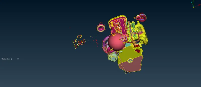
- Let's take a look at our model in its wireframe mode now to have a better idea of where the topological defects are.
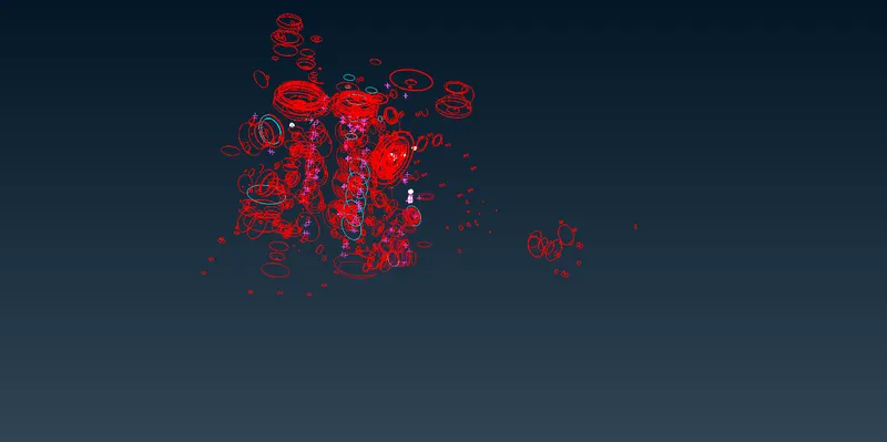
- In the wireframe mode of our model, we are able to spot flaws such as single cons, triplecons, and other such mistakes. Let's go through each topo error and fix it one at a time.
B.) Locating and rectifying errors in the topological and geometric structures:
- We noticed that the geometry we were given contained a number of topological mistakes before we performed any kind of topo clean up.
- In order to accomplish surface wrapping, we need to construct the components in such a way that there are no unwanted surfaces or components outside the geometry.
- To begin, we can see a large number of unchecked surfaces, which are to be directly selected by using the show only command and then deleted. These are the surfaces that have a length or width that is less than the minimum required for the mesh, and they are not supposed to have any significance and do not have any.
- We can see the surface that has not been checked off in the image that follows; in order to delete it, we need to drag and select all of it first.
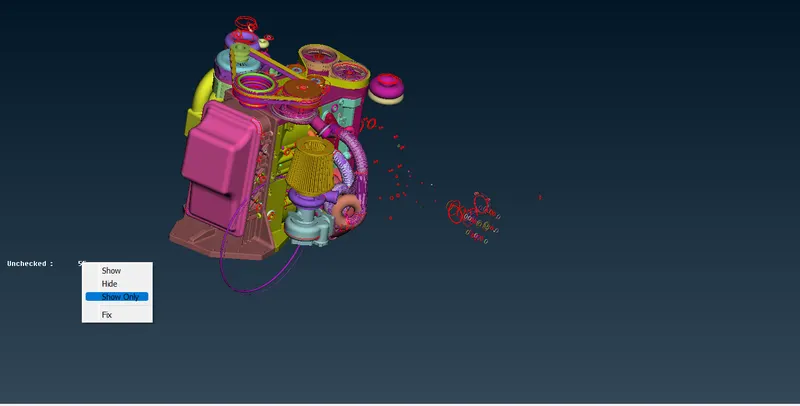
- At this point, we are considerably more worried with the outside aspects of the models as opposed to the inside amenities. We begin by removing the undesirable exterior surfaces, and then we repair the surface if there are any holes or open areas. This ensures that we do not introduce any errors into the wrapping process.
- We eliminate the undesired surfaces by using universal delete and selecting directly or by box selection, and then we delete them by adjusting the view to something more comfortable.
- We should mostly estimate the undesirable surfaces by seeing the circular rings or discs that have been generated to make certain slots or fillets in the design. Additionally, we should erase unwanted surfaces that are far away from the primary geometry and do not have any relation to it.
- If you are unsure about the decision, always zoom in and make sure that you are choosing the appropriate surface. In order to make an accurate selection, you need also switch to wireframe mode (Ctrl + Shift, or just turn off shadow mode).
- We need to get rid of the duplicate surfaces as well, and if you want to do so, you may conceal the top section and get rid of the undesired additional surface within.
- We will go through each surface and delete any that are deemed to be unnecessary one at a time. After we have finished removing some visible surfaces, it is best to hide any major PID or necessary required surfaces. Once we have done that, we will find a large number of surfaces that can be removed without causing any harm, and we will then delete all of them simultaneously.
- The majority of the needed surfaces in this case are those that do not have the form of a ring.
- As we go through the process of selecting the necessary surfaces, we may switch the selection type from PID to PID reg or entity, depending on the circumstances.
- Additionally, the selecting process is carried out in wireframe mode.
- The picture that is shown below is of the surfaces that are left after needed surfaces have been hidden. We erase all of these surfaces at once by utilising the universal delete function.
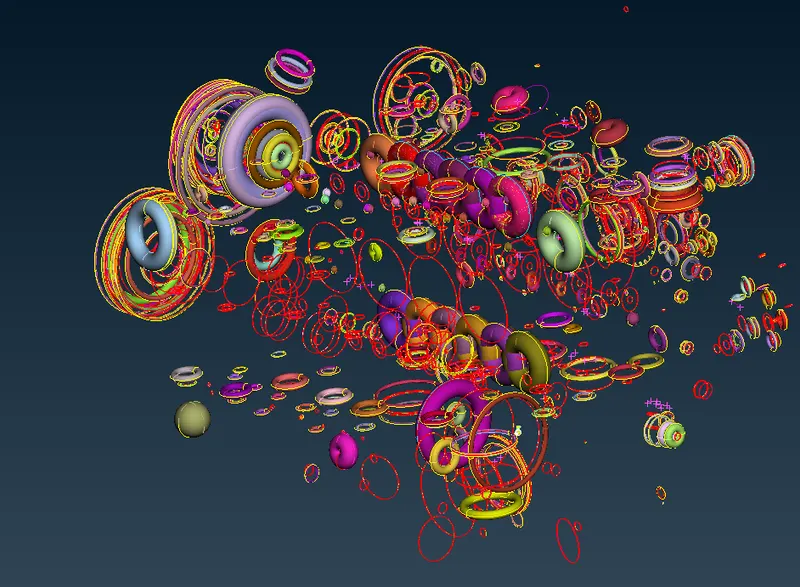
- As we are performing surface wrap, it generates wrap just on the top portion and keeps the interior section hallow, therefore there is no issue with triple conoverlapped surfaces or inner surfaces in this case. This is because it makes the complete three models into a single volume after the wrap is done. After finishing the wrap, we simply removed all of the surfaces that were not required in order to guarantee that there would be no errors.
- Last but not least, check to see that we haven't deleted any necessary surfaces or made any mistakes with the exterior surfaces.
- If we leave these outside ring types of surfaces undeleted, they will also be present in the wrap, which will modify the form of the surface wrap from what it really is. This is undesirable.
- To get accurate results from the CFD simulation, we need to get rid of such surfaces.
- You will see that our surfaces or geometry is much improved after such surfaces have been deleted, as compared to prior.
- You can see that we have eliminated all topo errors in the picture that follows; the next step is to save this model and then open another model.
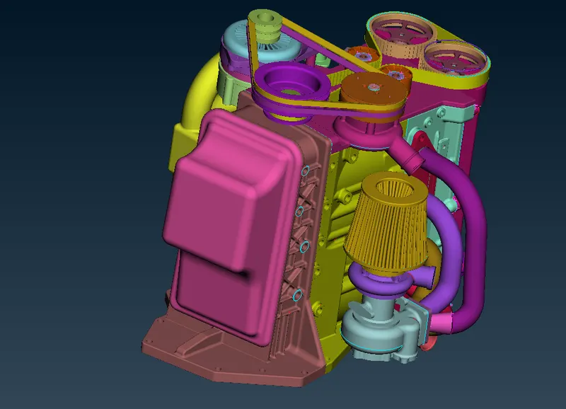
- If there are any topo errors in the other two models, need to get rid of them by using the methods outlined above.
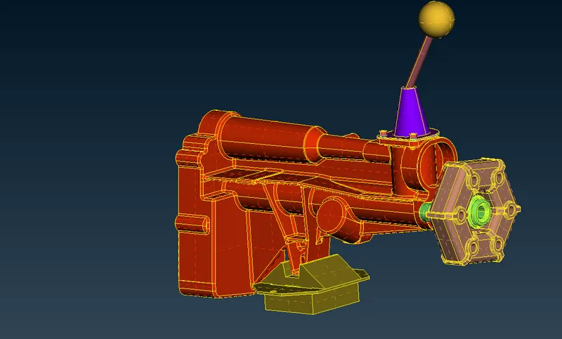
Model -2:- Gear box:
- The PID mode of our gear box model may be seen in the picture that follows once it has been imported.
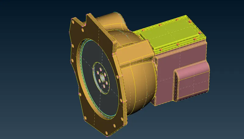
Model -3:- Transmission model:
- The PID mode of our transmission model may be seen in the picture that follows once it has been imported.
C) Filling in the open areas and gaps in the model, as well as integrating the previous three models:
- The manner that we do this is as follows: first, we clear or patch the open surfaces and holes in our engine model; next, we combine the other two models into the same file; finally, we repair the holes in the other two models.
- Before we begin filling in the holes for the engine model, we can see that the pulley has belts already. This is before we begin filling in the holes.
- Those are shown in the graphic that may be seen below.
- We do not need to keep the belts on the pulley since it is rather thin, and the surface wrap for them will not be caught very well.
- After sealing all exposed surfaces on the model, the engine can be seen in the picture below.
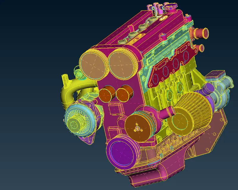
- Let's combine all three models at this point and fill in any gaps that exist in the other two models, if there are any.
- In order to combine the three models into one user interface, we must first pick merge from the file menu, then open the file we want to combine, then select merge action from the resulting pop-up window, and last, click ok.
- Similarly, I'll create a third file and integrate it in the same manner, creating a unified user interface for all three models.
- After combining all three models together, the resulting entire model can be seen in the picture below.
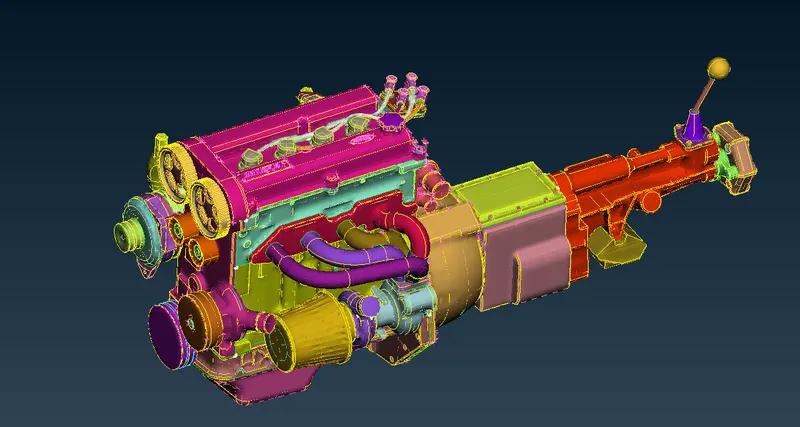
- Therefore, it is safe to say that all of the topographical flaws have been fixed, and the model is now prepared to be meshed.
D) In order to conduct surface wrap for the merged model, it is necessary to first set the mesh parameters and then pick the kind of meshing to use.
- Let's use compress to get rid of all of the unused and empty PIDs before we begin the surface wrap wrap.
- The subsequent step is to do the surface wrap.
- For us to be able to execute surface wrap, we need to complete the procedures below.
We need to go to the mesh deck, then under elements pick wrap, then under wrap select constant length, then a pop-up box will appear, then we need to double-click on empty under status, then another pop-up box will appear, then we need to provide a name for the wrap, then we need to double-click on perimeters to give a goal length (for example, 3 millimetres), then we need to keep the other options as default (nodes out of structure), then we need to select PID's
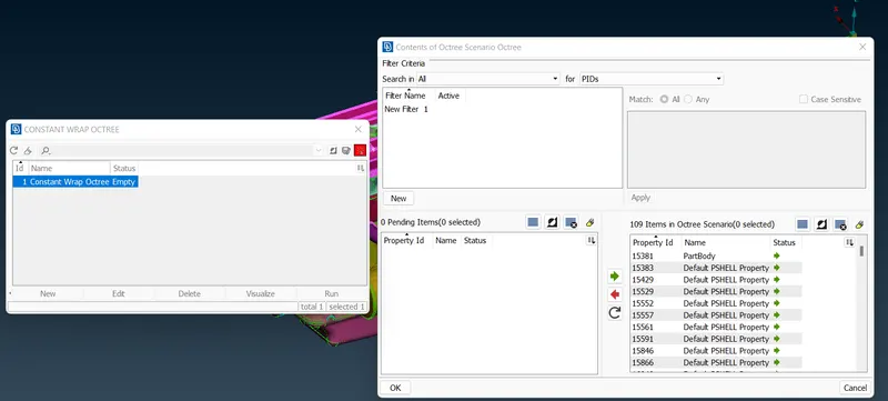
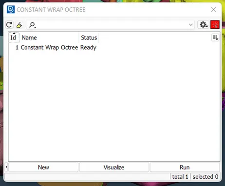
- After some time has passed, you will see that the status has changed to "ready" from "empty." The next picture demonstrates the same idea for your perusal.
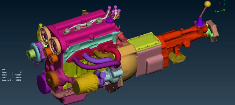
- After the surface wrap operation has been completed, the final look of the mesh/wrap can be seen in the picture below. The intended mesh length was 3 millimetres.
The following is a result of learning:
- During the course of our work on this project, we have acquired the skills necessary to,
- Locating and correcting any topological or geometric flaws across all three models.
- Combining all three of the existing models.
- Setting the mesh settings, selecting the kind of meshing to use, and carrying out surface wrap for the merged model are all tasks that need to be completed.
Concluding remarks:
- We were able to successfully integrate all three components, and we finished the meshing process for the final merged model by applying surface wrap to the meshes. Our desired mesh length was 3 millimetres.
Google Link:
https://drive.google.com/file/d/182i5nDrVseDFNSKW9Oqq18cMxCBceBPx/view?usp=sharing
https://drive.google.com/file/d/182i5nDrVseDFNSKW9Oqq18cMxCBceBPx/view?usp=sharing