Week 5 Challenge : Surface wrap on Automotive Assembly
AIM:
To clear all the errors in the given geometry and to delete the un necessary surfaces. Then have to assemble the models given. And then to perform the surface wrapping with the target length of 3mm.
DEFINITION - SURFACE WRAPPING:
Surface wrapping is similar to the process of the surface meshing but the analyst only focussing on the outer surface of the component not the internal volume. It wrap the surfaces with sheet of macro elements. The surface wrapping is commonly used for the complex geometries with various PIDs.
NEW TOOLS LEARNT:
- Merge (Used to assemble one or more components into the geometry)
- Elements ---------> Wrap -------> Constant length (Used to do the surface wrapping)
PROCEDURE:
1. Geometry checkup:
Whenever we loaded the new geometry into the ANSA, initially we have to check whether the dimensions of the geometry is in which unit of measurement. After that we have to observe the errors in the geometry by the wireframe model. And then we have to run the geometry checkup option to view all the geometrical and intersection errors in the geometry.
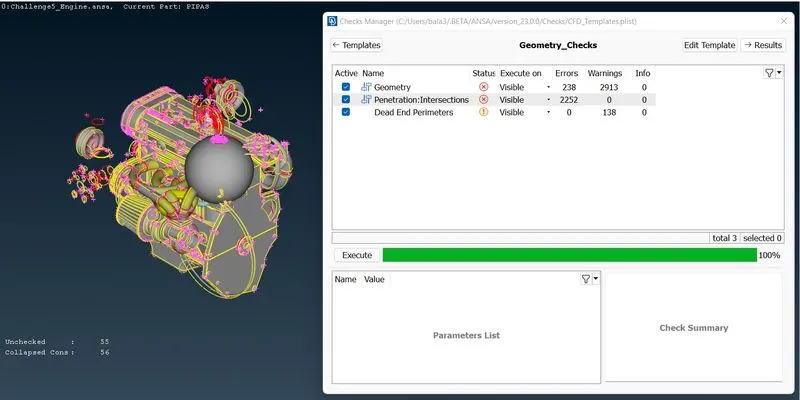
By seeing the results we got to know that there is a lot of intersection and geometrical errors in the geometry. So by understanding the geometry features we have to carefully remove all the errors in the geometry.
2. Error rectification:
This is the view of erros in the PID mode.
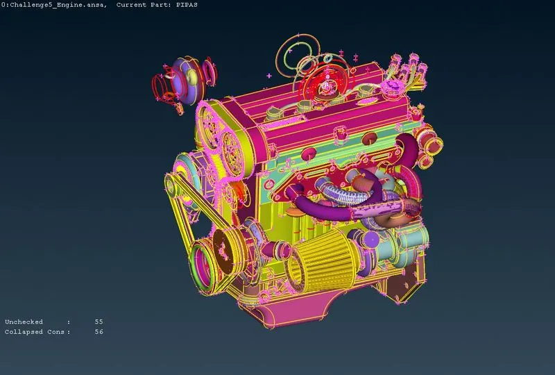
This is the majority of the error found in the geometry. This errors are not relavant to the geometry so that we can directly select these errors. But before that we have to carefully check whether the part which is a part of the engine is removed from these errors or not using NOT option.
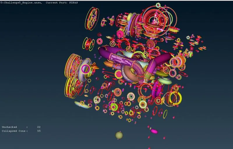
After deleting all these errors our geometry look like the image attached below. But in that geometry itself there is a lot of un needed shapes like this. This is due to the fillet option used by the designer at the edges, where instead of fillet option they use revolve option to do the same. So we have to delete the unwanted parts,
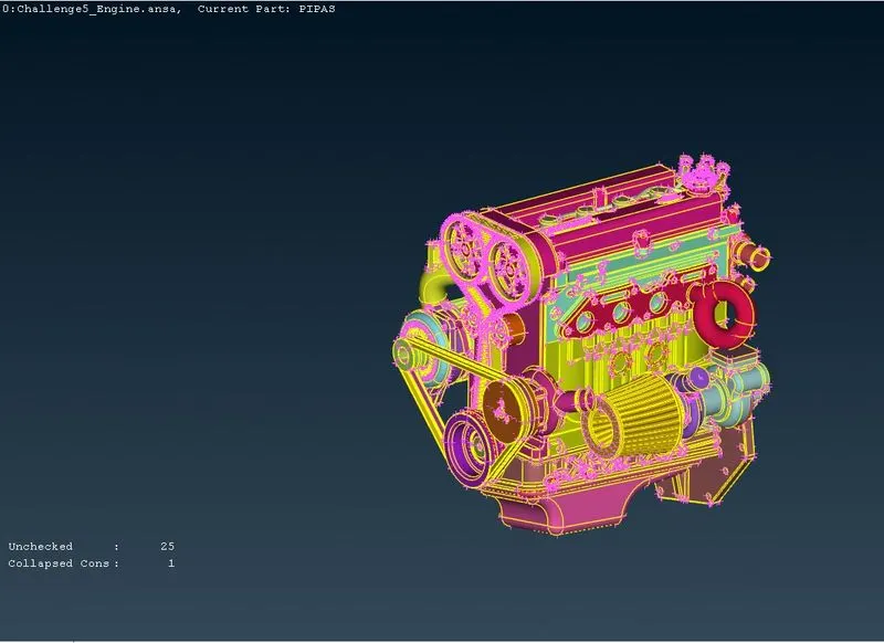
After clearing all the errors, we got our actual geometry, where we consider the outer most error in the geometry to do the surface wrapping. And after that holes in the surfaces have to be closed to perform the surface wrapping operation because during the wrapping the mesh sheet will got deformed in that holes.

With similar to the approach we have to clear all the errors in the Transmission as well as gearbox geometry. There might not be any unchecked faces and collapsed cons in the geometry. And we have to make sure that no geometrical errors are present in the outer surface of the geometry as we are focussed to do the surface wrapping
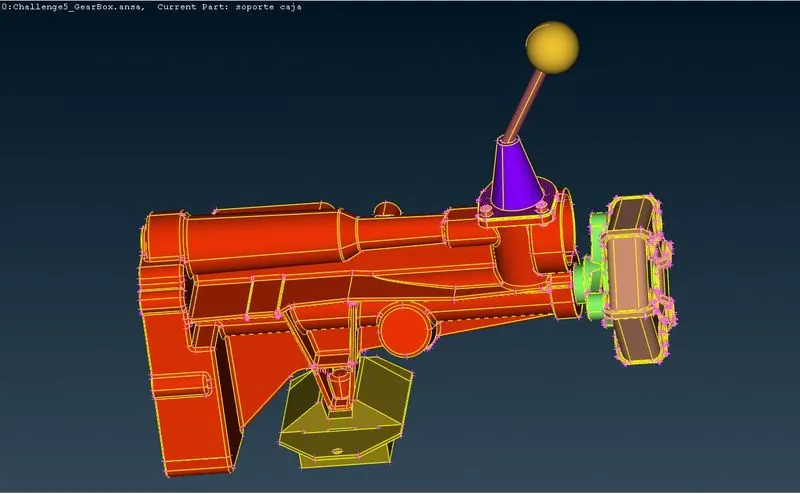
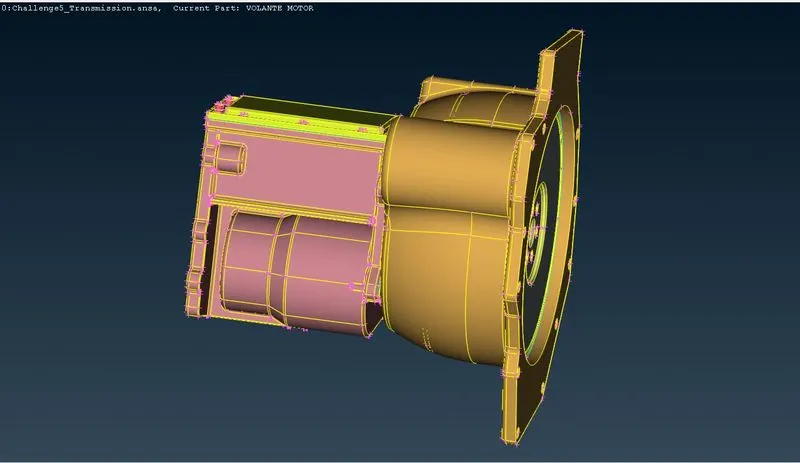
3. Assembling the Components:
After clearing all the errors, we can then assemble each components inorder to create the entire geometry. Initially we have to choose the main part of the component that is the base part of the assembly initialisation. Then we have to go for the File --------> Merge option to do the assembly. After clicking that the popup will appear. On that we have to select the part that is going to assemble on our base part. Then we have to click open.
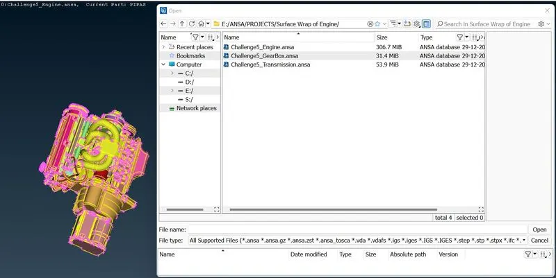
Then we have to click OK to start the assembling process.
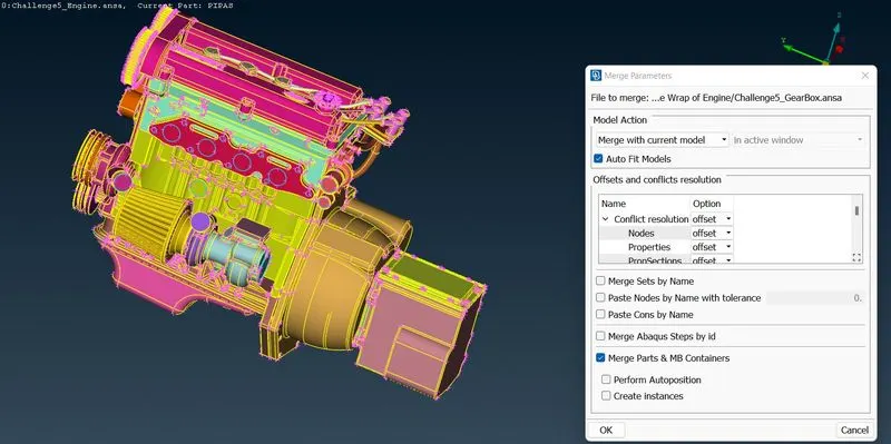
After that the assembled part will be like it in the image shown below.
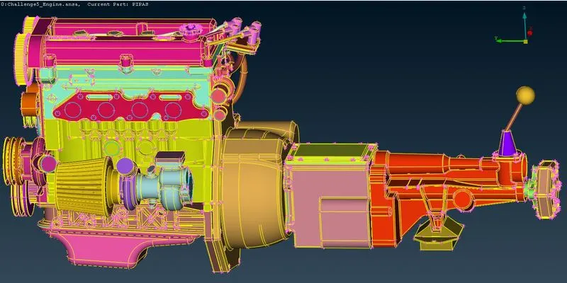
4. Surface Wrapping:
After the overall assembly of the is done then we can do the surface wrapping. For doing that we have to go for the Elements -------> Wrap --------> Constant length option. The dialog box attached below will gets pop up. On that we have to click new to feed the data for meshing.
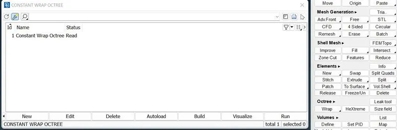
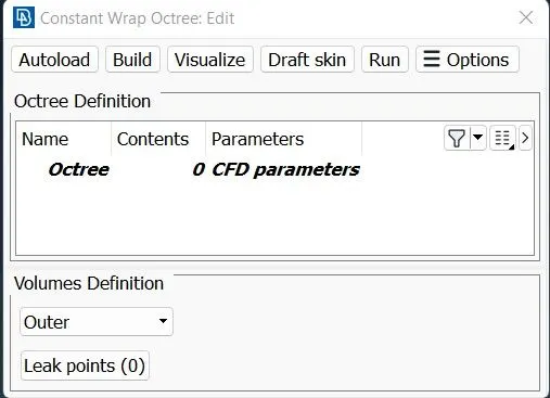
After clicking new one dialog will appear. New selection option will appear with the contents and parameters. On that we have to select the content and have to load the required parameters to perform the operation.
While clicking the 0 in the contents icon, we will then redirect to the another dialog box where we have to select the PID required for doing the meshing with particular parameter. So that we can easily choose the mesh target length for specified PID. After selecting the PID we have to click OK.
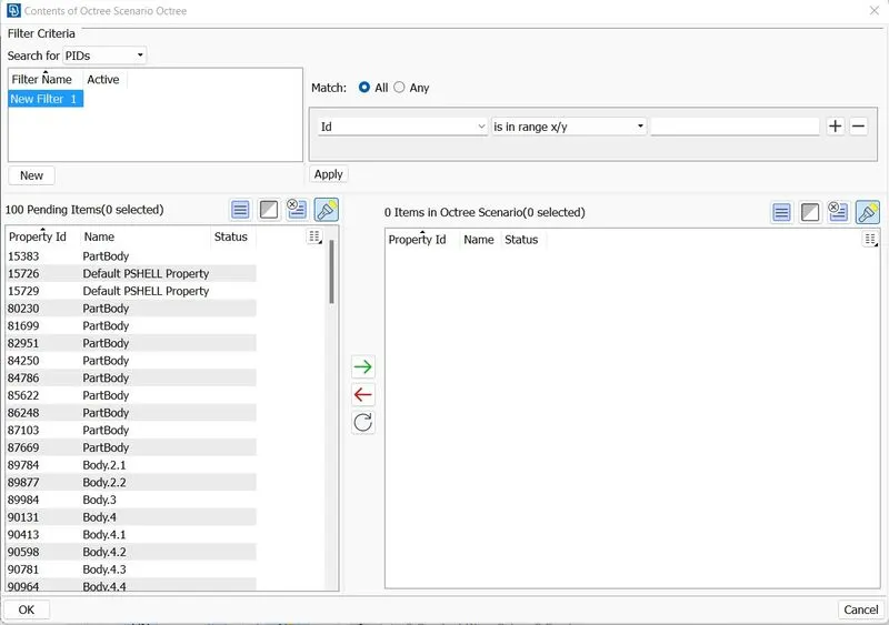
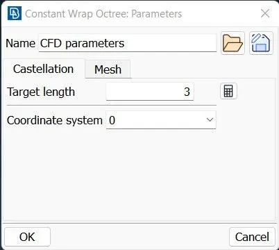
Then we have to click the Parameters to load up the parameters of the meshing. One dialog will appear, on that we have to define the target length for the particular PID. Then on the same dialog box there is a option called mesh. By clicking that we can define the type of the mesh required for our geometry. By selecting all this depending upon our requirement, then we can click OK.
Here for our geometry we choose our Target length as 3mm, and Mesh type as Tria Element.
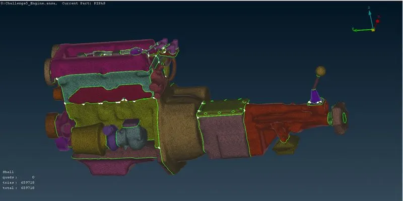
After that we have to click Run to run the meshing parameter on our geometry. After the meshing process is completed it will look like the image attached below.
RESULT:
So thus we clear all the errors in the geometry considering the surface meshing. And we do assemble the parts using the Merge option. And then we perform the surface wrapping with the Tria elements of 3mm target length.
LEARNING OUTCOMES:
After this project we get to know what surface wrapping is. And what is the application of surface wrapping and How to do the surface wrapping in the ANSA.