Week 5 Challenge
1.Generate manual wind loading in the design report based IS code as per the following input
- Basic wind speed = 39m/s
- Terrain category 2
Ans)
Aim:To generate manual wind loading in the design report based IS code as per the following input which are mentioned in the question.
Tools Required:
-> Tekla model
-> Dimensions
-> Microsoft Excel Worksheet
Procedure:
- Firstly open the Tekla softwear and open the designed model for which you desired to apply wind load.
- Now take the dimensions of the model such as height, lenght,width etc.
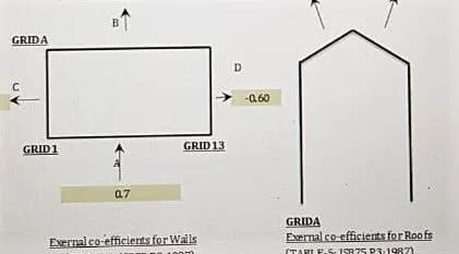
- Now place the values in the Microsoft Excel Worksheet and type the required content.
- Multipy the factors as in when required.
| Wind load calculations as per IS: 875 P3-1987 | ||||||||||||
| Basic parameters | ||||||||||||
| Basic wind speed Vb= | 39 | m/s | Terrain category= | 2 | ||||||||
| Probable design life= | 50 | years | class of structure = | A | ||||||||
| Greater horizontal dimension, l= | 24 | m | Ratio for wall and roof co-efficients: | |||||||||
| Lesser horizontal dimension, w= | 18 | m | ||||||||||
| Eaves level height = | 14 | m | wall = | l/w = | 1.33 | |||||||
| Width of frame-1, grid A and B | 7 | m | h/w = | 0.78 | ||||||||
| Roof = | h/w = | 0.78 | ||||||||||
| Topography factor, k3= | 1 | |||||||||||
| Risk co-efficient, k1= | 1 | (for 50 years) | ||||||||||
| Height(m)= | upto 10 | |||||||||||
| Terrain factor & str.size factor k2= | 1 | |||||||||||
| Important factor for cyclonic, k4= | 1.15 | |||||||||||
| Design wind speed , Vz= Vb*k1*k2*k3*k4= | 44.85 | |||||||||||
| Design wind pressure (N/m) | (N/m^2), Pz= 0.6*vz^2= | 1206.9 | ||||||||||
| Design wind speed(kN/m^2), Pz = | 1.207 | |||||||||||
| Roof angle, α = | 16 | degree | ||||||||||
| Internal pressure coefficient, α = | 0.5 | (upto 20% opening) () | (Cl.6.2.3.3 IS 875 P3:1987) | |||||||||
| Internal pressure coefficient, α = | -0.5 | (upto 20% opening) () | ||||||||||
| Wall loading calculations : | ||||||||||||
| Wind direction : +Y | ||||||||||||
| Wind load along Y-Direction | (Face A): | _+ Cpi | _- Cpi | |||||||||
| Height at different level = | upto 10 | upto 10 | ||||||||||
| External pressure coefficient, Cpe = | 0.7 | 0.7 | ||||||||||
| Internal pressure coefficient, Cpi = | 0.5 | -0.5 | ||||||||||
| Net pressure coefficient, Cp = | 0.2 | 1.2 | ||||||||||
| Design wind pressure for wall = | 1.207 | 1.207 | ||||||||||
| Loading to be applied on the wall = | 0.241 | 1.448 | ||||||||||
| factor ( loading * 1.05) = | 0.253 | 1.52 | ||||||||||
| Wind load along Y-Direction | (face B): | _+Cpi | _-Cpi | |||||||||
| Height at different level = | upto 10 | upto 10 | ||||||||||
| External pressure coefficient, Cpe = | -0.25 | -0.25 | ||||||||||
| Internal pressure coefficient, Cpi = | 0.5 | -0.5 | ||||||||||
| Net pressure coefficient, Cp = | -0.75 | 0.25 | ||||||||||
| Design wind pressure for wall = | 1.207 | 1.207 | ||||||||||
| Loading to be applied on the wall = | -0.905 | 0.302 | ||||||||||
| factor ( loading * 1.05) = | -0.95 | 0.32 | ||||||||||
| Wind load along Y-Direction | (Face C & D) | _+Cpi | _-Cpi | |||||||||
| Height at different level = | upto 10 | upto 10 | ||||||||||
| External pressure coefficient, Cpe = | -0.6 | -0.6 | ||||||||||
| Internal pressure coefficient, Cpi = | 0.5 | -0.5 | ||||||||||
| Net pressure coefficient, Cp = | -1.1 | -0.1 | ||||||||||
| Design wind pressure for wall = | 1.207 | 1.207 | ||||||||||
| Loading to be applied on the wall = | -1.328 | -0.12 | ||||||||||
| factor ( loading * 1.05) = | -1.4 | -0.13 | ||||||||||
| Roof loading calculations | ||||||||||||
| Wind direction -Y | _+Cpi | _-Cpi | ||||||||||
| h/w = 0.78 | h/w = 0.78 | |||||||||||
| External pressure coefficient, Cpe = | -0.88 | -0.4 | -0.88 | -0.4 | ||||||||
| Internal pressure coefficient, Cpi = | 0.5 | 0.5 | -0.5 | -0.5 | ||||||||
| Net pressure coefficient, Cp = | -1.38 | -0.9 | -0.38 | 0.1 | ||||||||
| Design wind pressure for roof, Pz = | 1.207 | 1.207 | 1.207 | 1.207 | ||||||||
| Wind load along X-direction ( Roof EG): | _+Cpi | _-Cpi | ||||||||||
| Height at different level = | upto 10 | upto 10 | ||||||||||
| External pressure coefficient, Cpe = | -0.76 | -0.76 | ||||||||||
| Internal pressure coefficient, Cpi = | 0.5 | -0.5 | ||||||||||
| Net pressure coefficient, Cp = | -1.26 | -0.26 | ||||||||||
| Design wind pressure for wall = | 1.207 | 1.207 | ||||||||||
| Loading to be applied on the wall = | -1.52 | -0.314 | ||||||||||
| factor ( loading * 1.05) = | -1.596 | -0.33 | ||||||||||
| Wind load along X- direction ( Roof FH) : | _+Cpi | _-Cpi | ||||||||||
| Height at different level = | upto 10 | upto 10 | ||||||||||
| External pressure coefficient, Cpe = | 0 | 0 | ||||||||||
| Internal pressure coefficient, Cpi = | 0.5 | -0.5 | ||||||||||
| Net pressure coefficient, Cp = | -0.5 | 0.5 | ||||||||||
| Design wind pressure for wall = | 1.207 | 1.207 | ||||||||||
| Loading to be applied on the wall = | -0.6 | 0.6 | ||||||||||
| factor ( loading * 1.05) = | -0.63 | 0.63 | ||||||||||
Result:
By doing this we will be able to generate wind load calculations of a model manually.
2.Based on the above calculation apply the loadings on the model.
Ans)
Aim:Based on the above calculation applying the loadings on the model.
Tools Required:
-> Loads
-> Loadcases
-> Area load
->Properties -> Direction -> Load value.
Procedure:
- Firstly open the model that was previously designed.
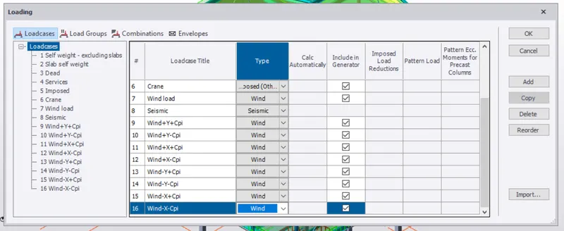
- Now select the load cases option, you will be directed to a dialogue box and in that add the load cases of your chioce and naming the load as wind load as we are doing that.
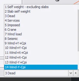
- I named the loads as shown in the above picture.
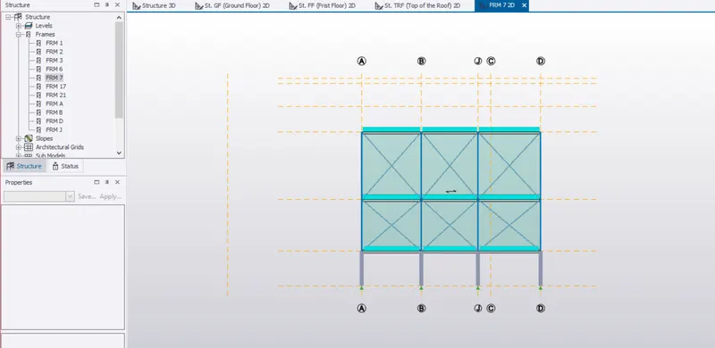
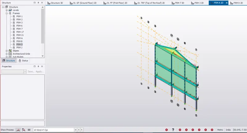
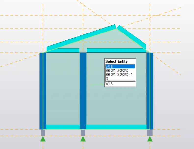
- Now in the below bar of the workspace assing a particular load to the frames that are to be assigned.
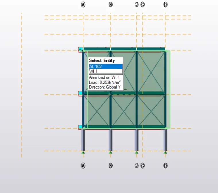
- Repeat the loads for the Faces of A,B,C and D accordingly.
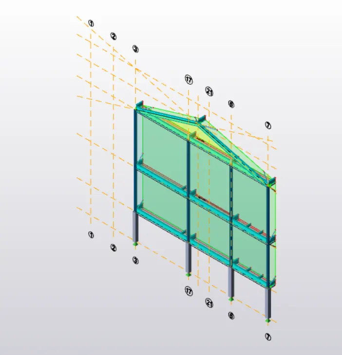
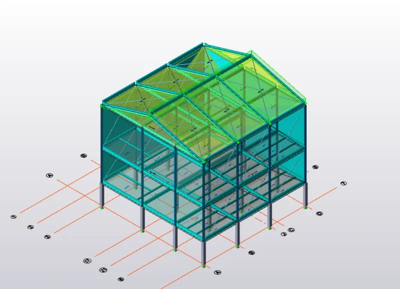
- Now assign the loads for the roof too.
Result:
Hence by following the above procedure we can applying the loadings on the model.
3.On a separate model generate wind loading using wind wizard.
Ans)
Aim:To create a separate model and generate wind loading using wind wizard.
Tools Required:
-> Levels
-> Manage Properties -> New -> Members -> Concrete Column.
-> Grids
-> Columns
-> Manage Properties -> New -> Members -> steel beam.
-> Beams
-> Properties tab
Load -> Wind Wizard
Procedure:
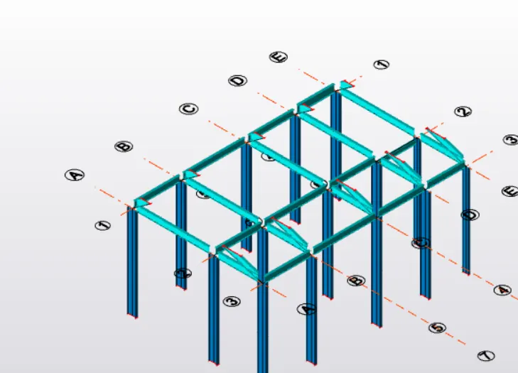
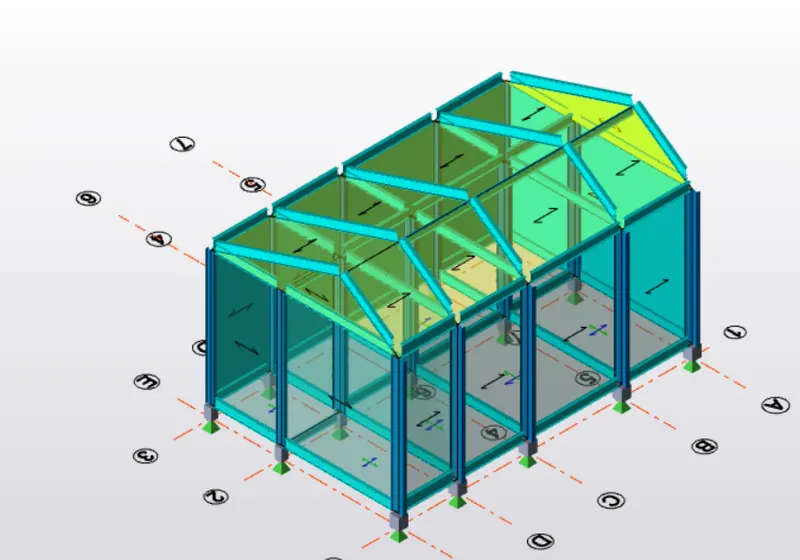
- Firstly on the workspace create a model of your choice.
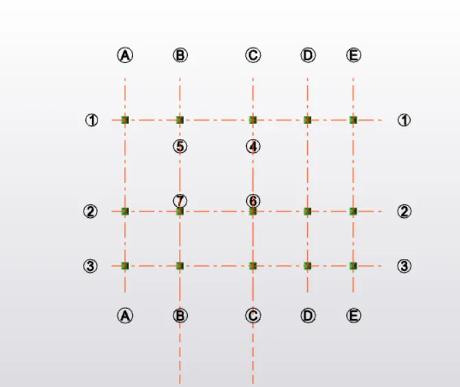
- That is to create the grids and then assigning the columns,beams as per the requirement for the building.
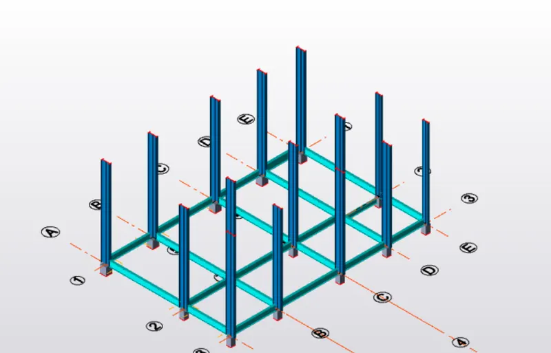
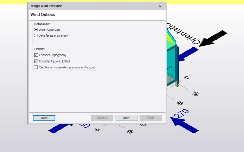
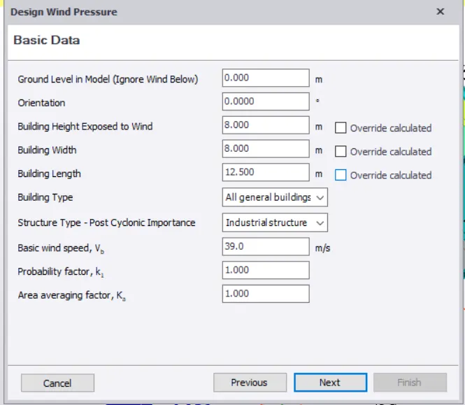
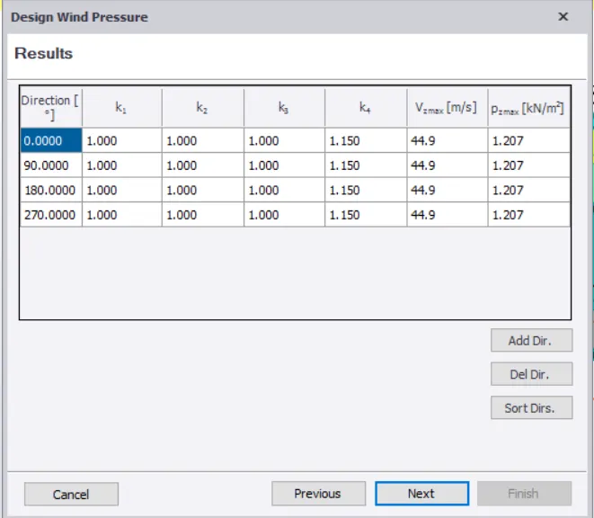
- Now select the wind wizard option and you will be directed to a dialogue box on the workspace.
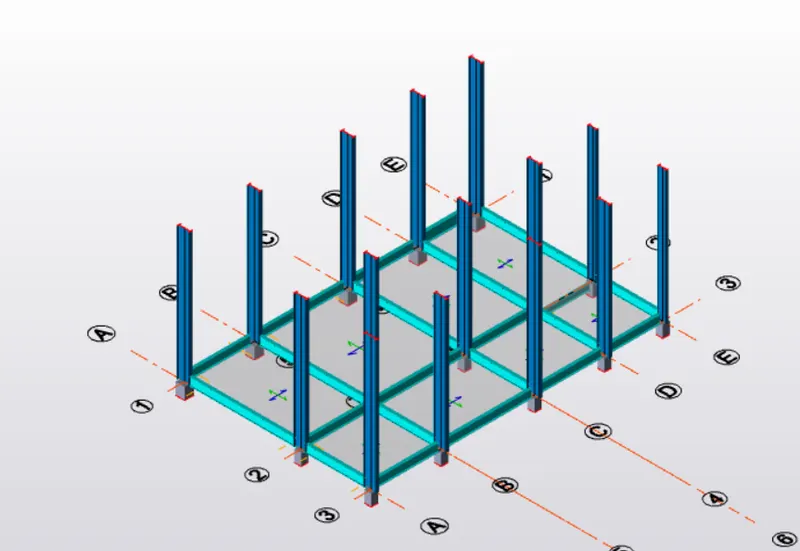
- Now select next and finish because all the values of the structure are already taken by the software itself and there is no values that you have to change.
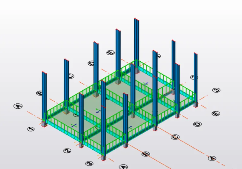
- Click ok and the work is done.
Result:
Hence by following the above procedure we will be able to create a separate model and generate wind loading using wind wizard.