REVIT_3D Rendering of a House Plan_Project 1
1.Question: Based on the project saved from Week 3, proceed from First Floor Level .Model a Ceiling from architecture tab above the walls at first floor level
Ans) AIM:To model a celling for the previously designed project with the help architectural tab above the walls at first floor.
TOOLS REQUIRED:
Architecture tab -> celling
modify tab -> pick line.
PROCEDURE:
- Firstly open the project with the ground floor and first floor.
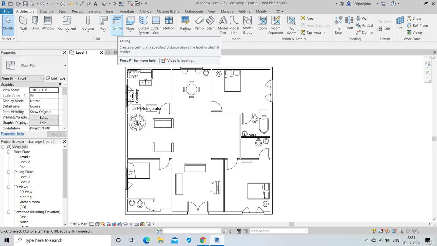
- Now go to the level 1 or ground floor view where in we find only that floor part .
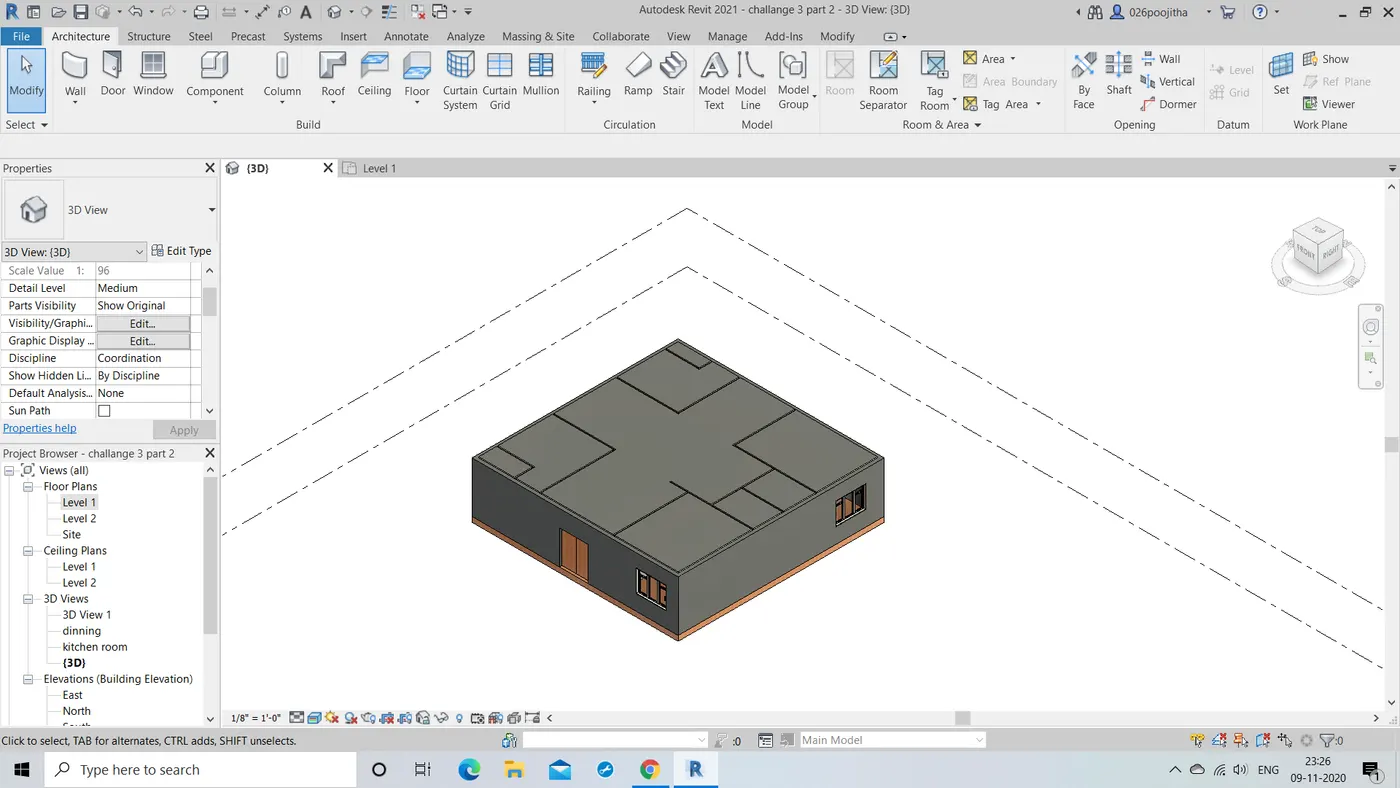
- Now with the help of architectural tab we find the celling option.
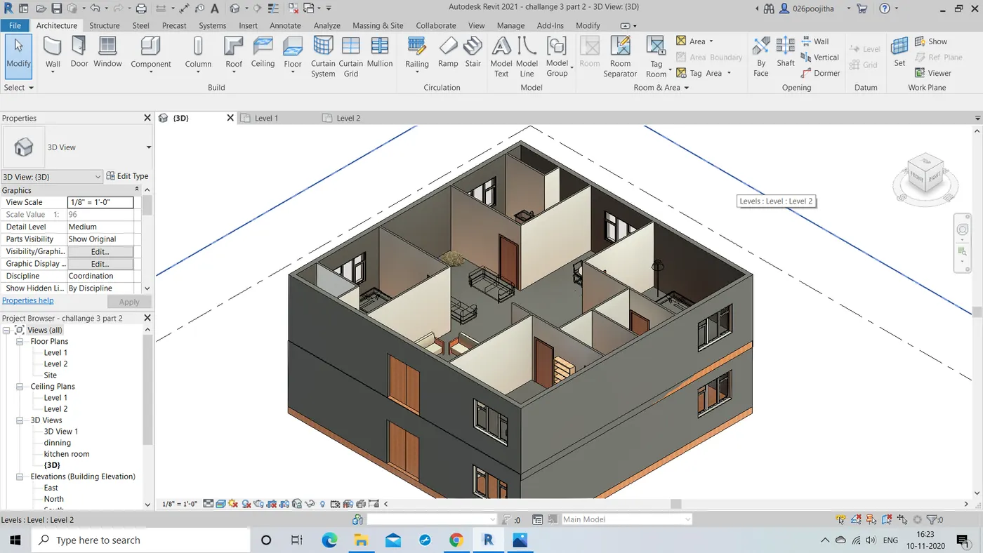
- Now by clicking the option we get to pick the lines or pick the boundaries option and draw the desired celling for the first floor.
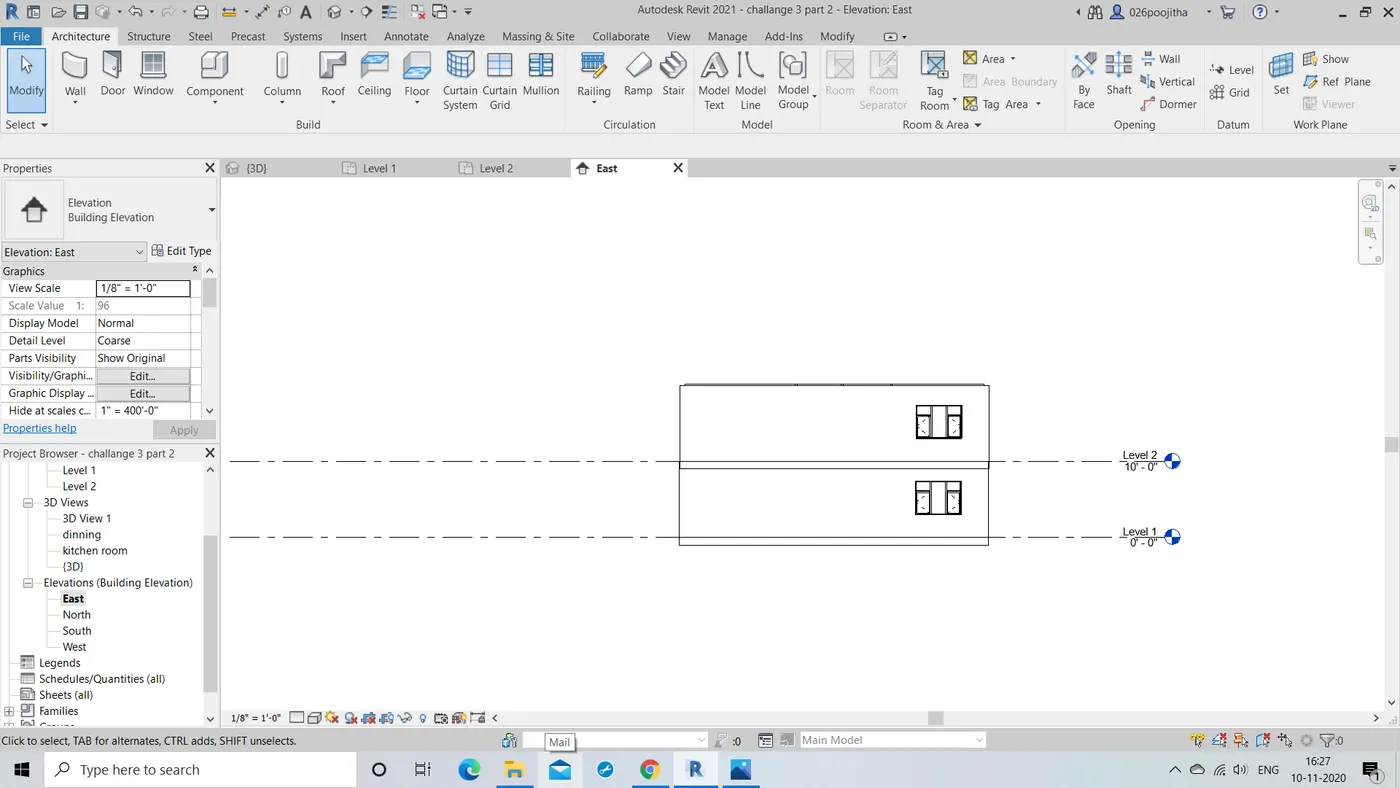
RESULT: Hence the desired model of the residential building with the celling for the ground and the first floor.
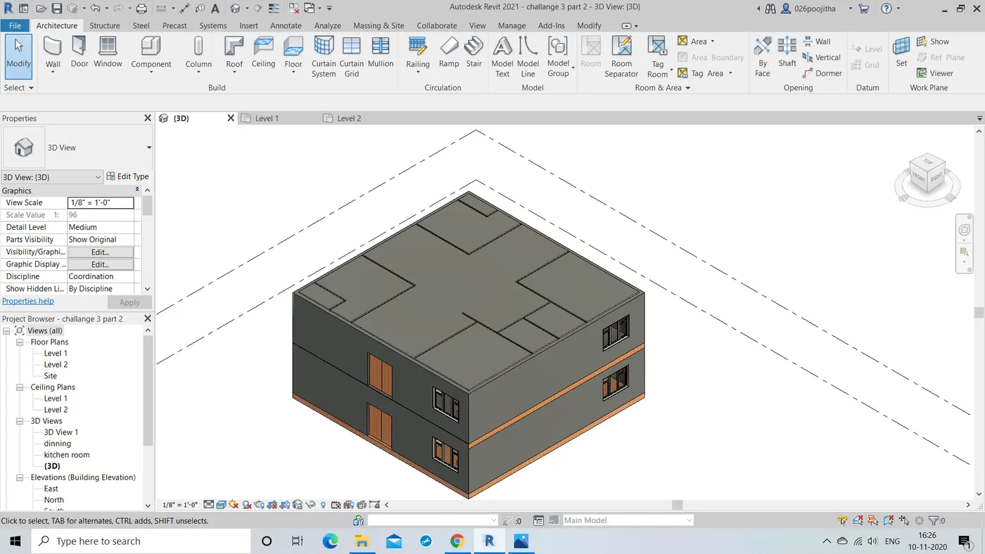
2.Question: Model a roof above the ceiling by selecting the footprints of ceiling. Using the adjustment tool bars appearing on screen adjust the roof slope to 10 degrees.
Ans) AIM: To model a roof on the above designed building and make it 10 degrees sloop roof with the help of adjustment tool bar.
TOOLS REQUIRED:
Architecture tool bar -> Roof
modify tool bar -> pick lines
properties drop down -> slop.
PROCEDURE:
- Firstly we need to open the drawing and now click on the roof option.
- Now we will be directed to modify tool bar where in we have to select the pick the lines option.
- Now on the drawing we need to select the exterior walls of the the building to place the roof appropriately.
- We will be able to see the roof.
- To make it 10 degrees slop roof we need to the properties and there the settings of the slope by clicking on it .
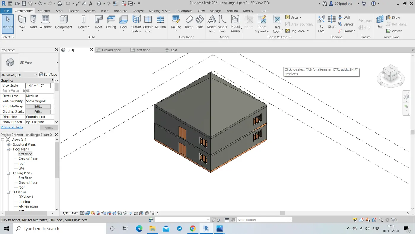
RESULT: Hence the desired 10 degree slop roof is found to be placed on the building.
3.Question: Using the file saved from week 2 to 4, create plan views for ground floor level and first floor level including all the walls , floors and components. Separate them to
architecture and structural plans
a. Architecture plan must have walls , floors and all the components placed within the building
b. Structure plan must have details of only walls, floors and columns
Ans) AIM: To create the plan view of the ground floor and the first floor including the walls,floor and other components
TOOLS USED:
Properties browser -> floor plans -> ground floor, first floor.
PROCEDURE:
- Now in the present working project we need to click on the floor plans option in the project browser.
- Now select the desired floor plan that we wanted to show first.
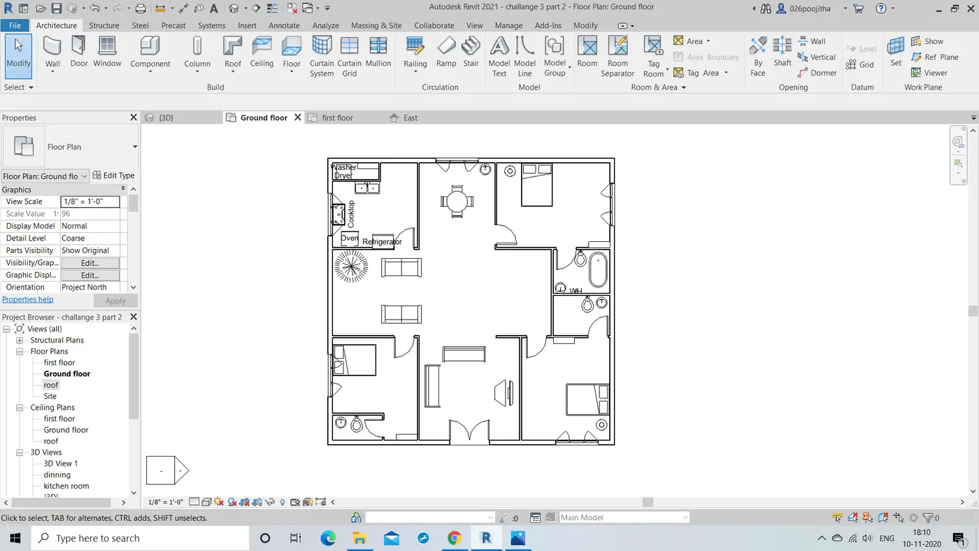
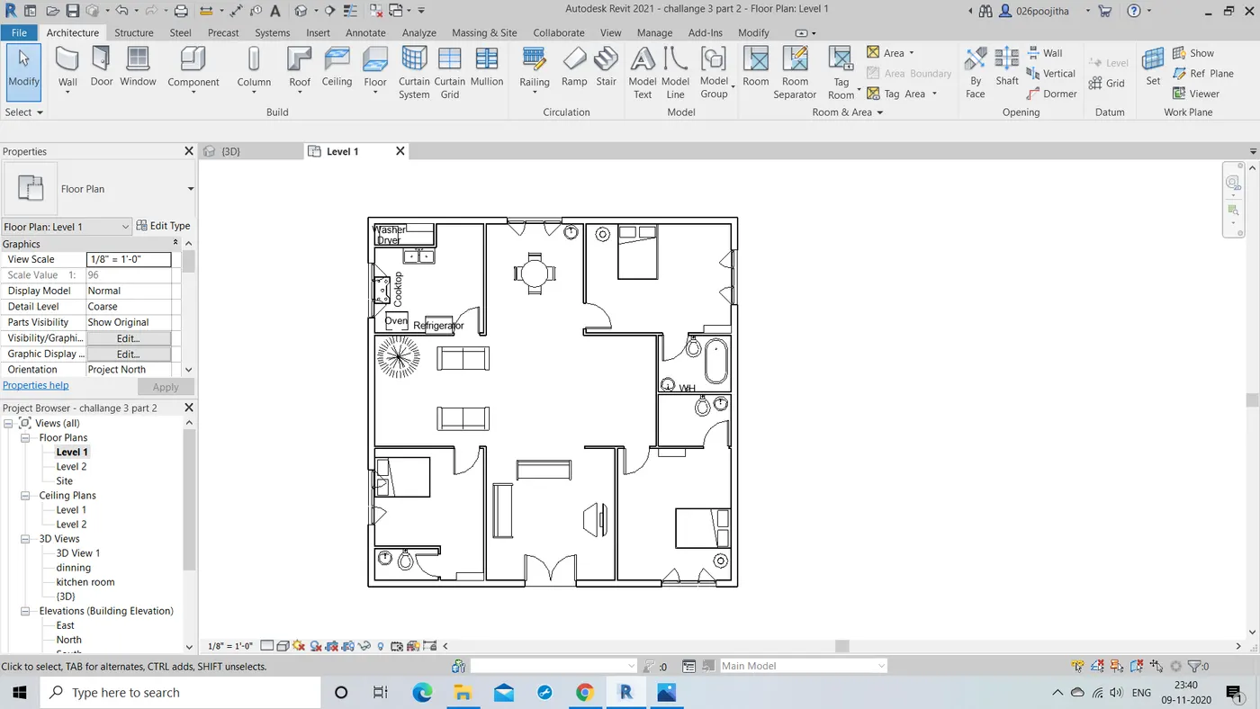
- I would like to select the ground floor plan first then we get to see the ground floor plan's architectural view.
- Now I would like to open the first floor view and we get to see the architectural view of the first floor.
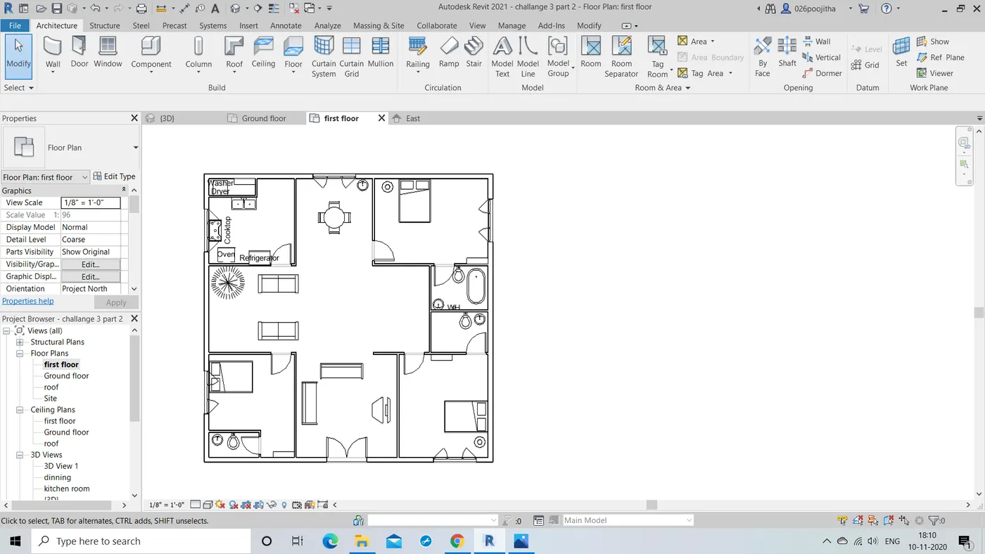
RESULT: Hence the architectural view of the the floor plan is executed perfectly.
NOTE: Structural plans aren't explained in this week session.
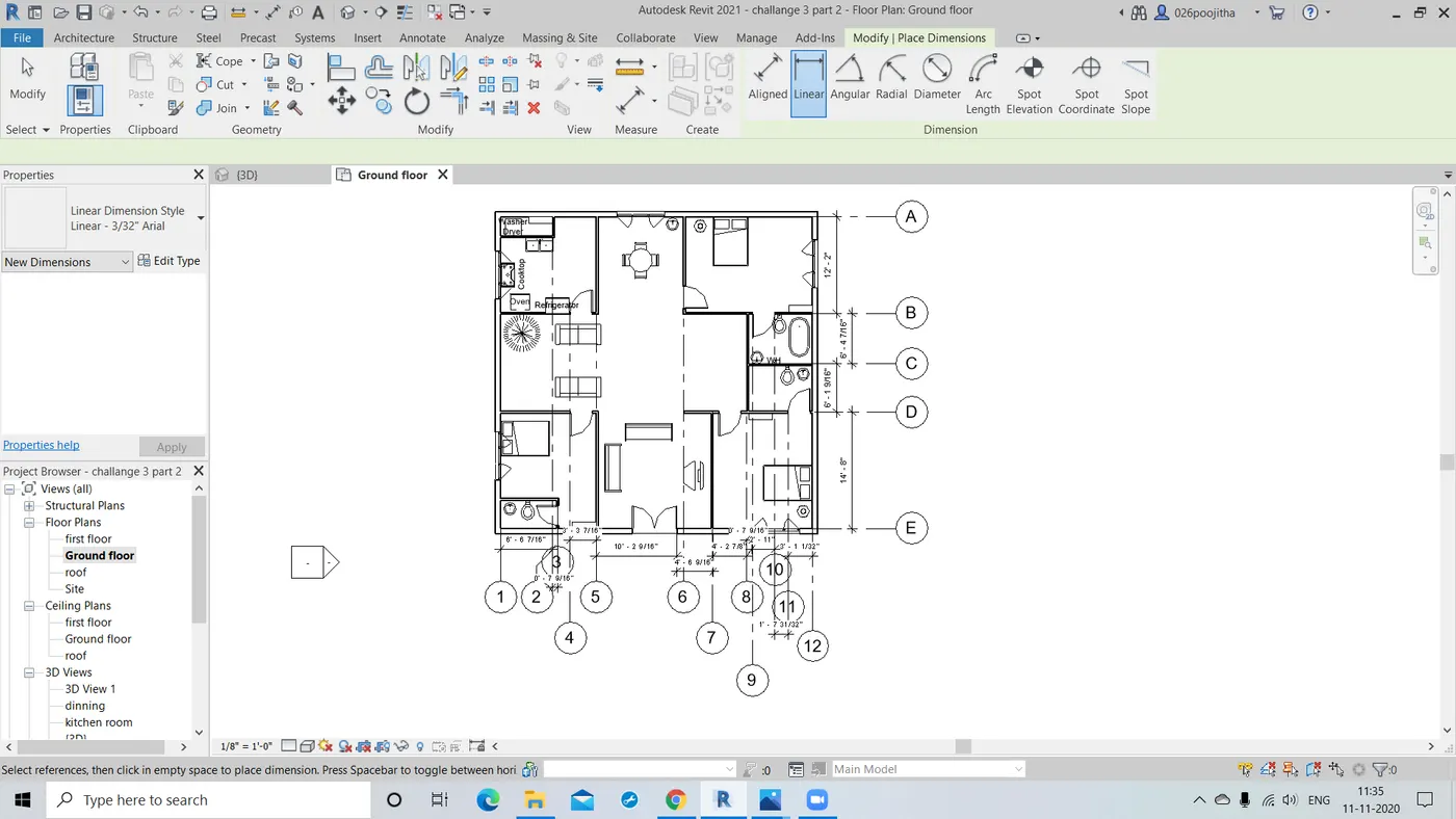
4.Question:Using annotate tool bar add dimensions to all the walls and floors with reference to the longitudinal and transverse grids created in the project file
a. The architecture plan dimensions include details on where the components are placed within the buildings with relation to grids. Overall dimensions are sufficient for architecture plans
b. The Structure plan dimensions must include details on position of all the walls and interior walls with reference to grids. Locate all the framing components of the building with reference to a fixed point using Structural plans
Ans) AIM: To add dimensions to all the walls and floors with reference to the longitudinal and transverse grids created in the project file.
TOOLS REQUIRED:
Architecture tool bar -> grids
Annotate -> aligned
PROCEDURE:
- Firstly select the architectural tool bar and with the help of grids option draw the grids
- That is to draw the horizontal and vertical grids.
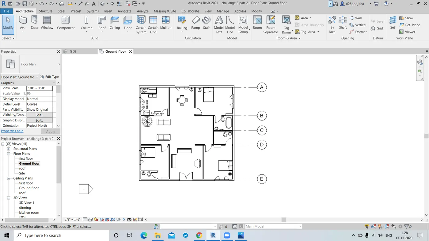
- Now to name the longitudinal girds name them A,B,C and so on from up to down.
- Now it is the same with the transverse grids name them as 1,2,3 and so on from left to right.
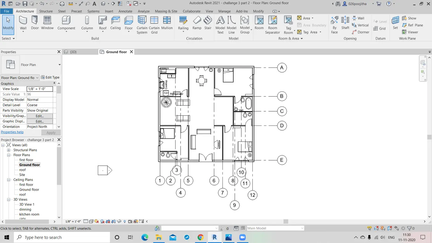
- With the help of aligned tool we can now measure the distance between the walls.
RESULT: Hence the dimensions are included properly in the architectural plan view.
NOTE: Structural plans aren't explained in this week session.
5.Question: Create a sheet template from the view tab and adjust the parameters on the sheet to add appropriate views.
Ans) AIM:to create a sheet template from the view tab and adjust the parameters on the sheet to add appropriate views.
TOOLS REQUIRED:
View -> sheets, E1 30 X 40 horizontal.
project browser -> parameters.
PROCEDURE:
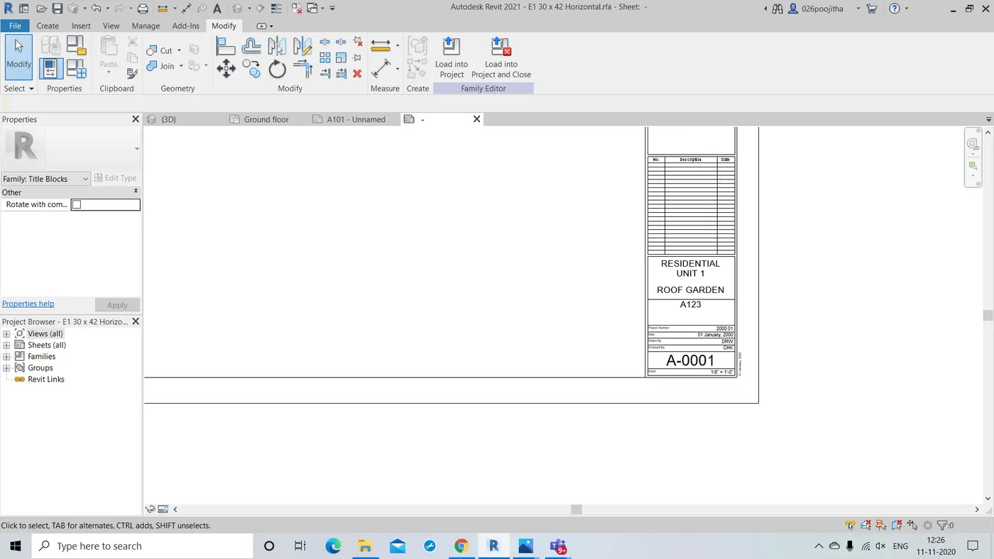
- Firstly open the view tab and click on the sheets.
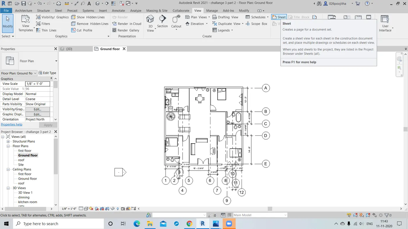
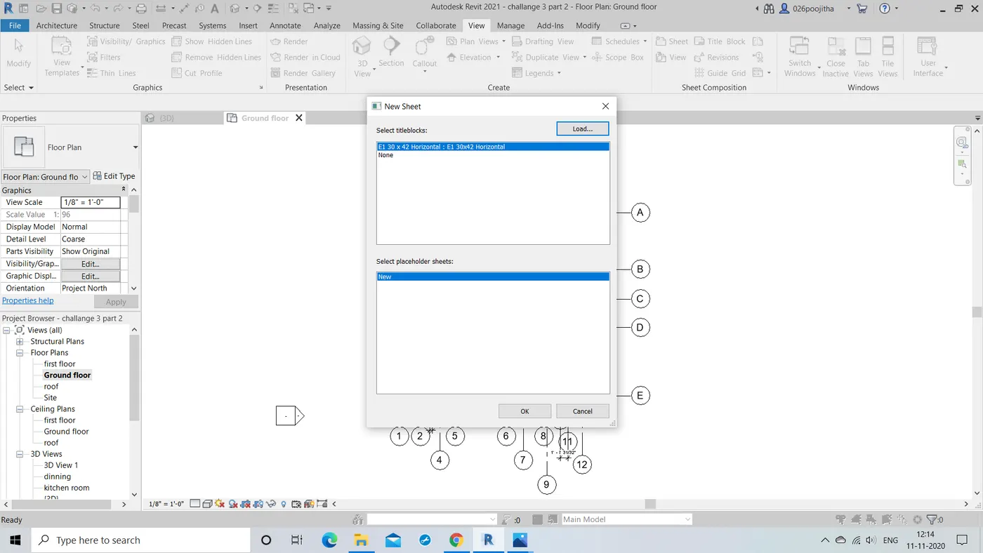
- A new dialog box opens and we need to select the desired type of sheet.
- Now clicking on the a new sheet opens with default naming .
- We can change the names with the help of properties drop down or by just clicking on the particular place itself.
- Now with the help of project browser change the parameters of the sheets.
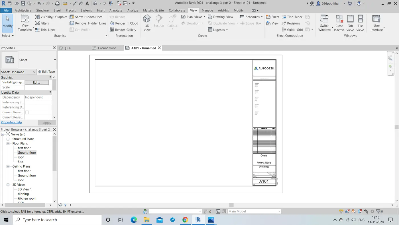
RESULT: Hence the sheets are created and named with appropriate parameters.
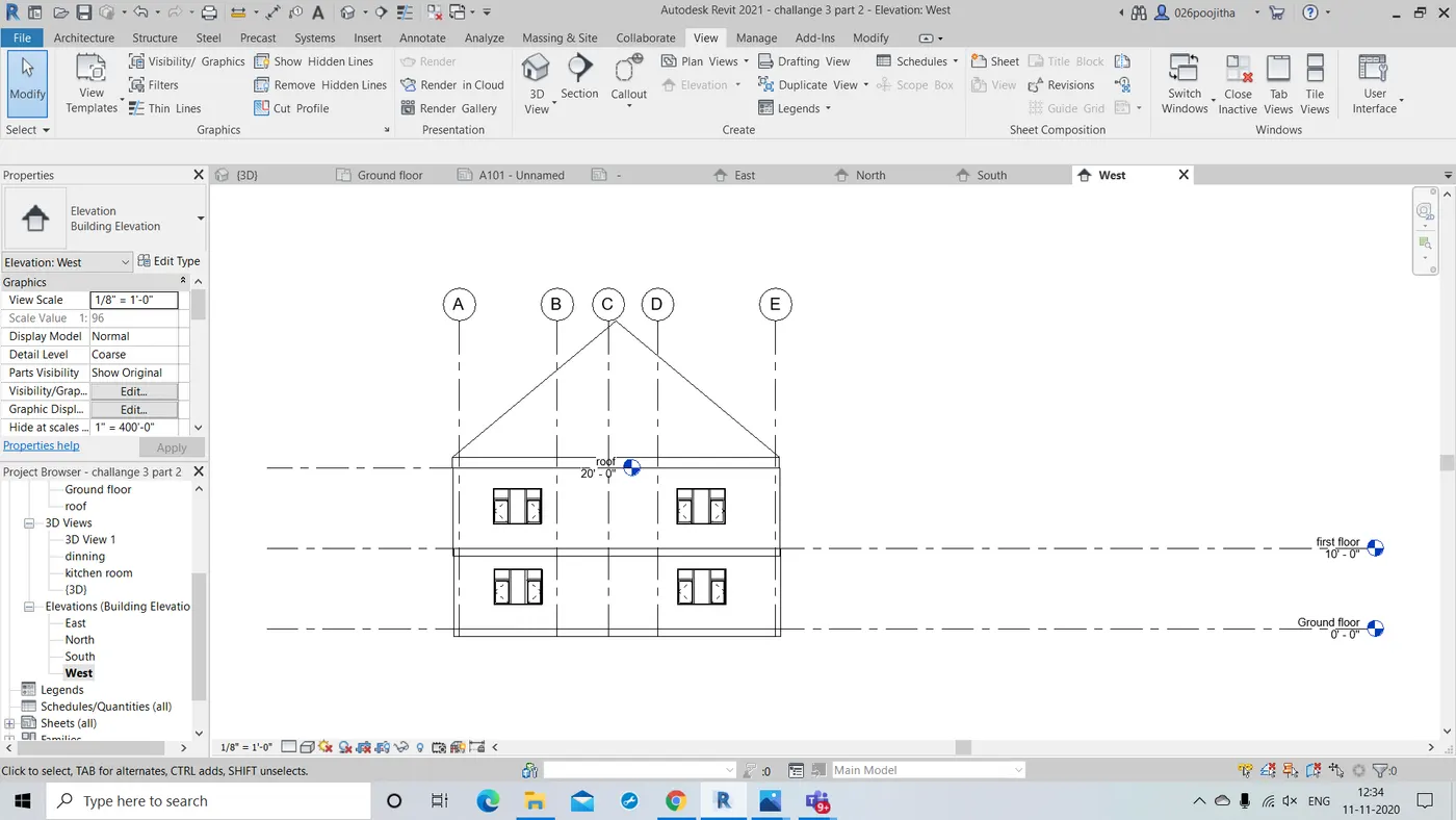
6.Question:Using the elevation tab create the elevation views, looking at your building from East, North, South and West.
Ans) AIM:TO show the elevation of the building in the north,south,east and west directions.
TOOLS USED:
View -> elevation
Project browser -> Elevation -> east,west,north,south.
PROCEDURE:
- Open the previous projcet and click on the view tool bar.
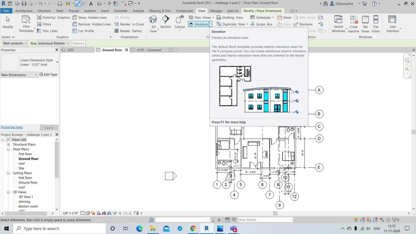
- Now click on the elevation option we are directed to the project browser.
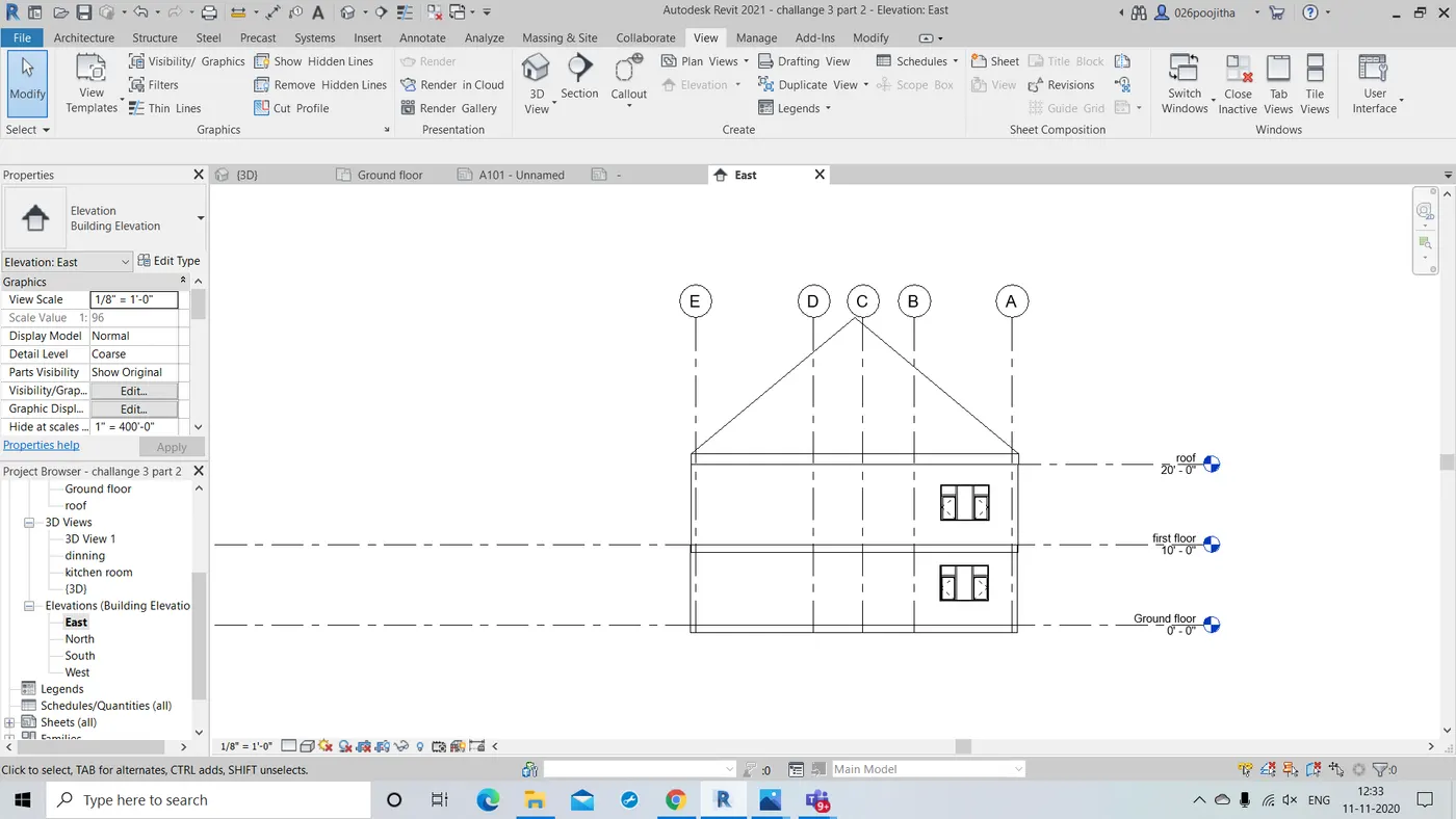
- Now click on elevation and a drop down box appears containing east,west,north,south.
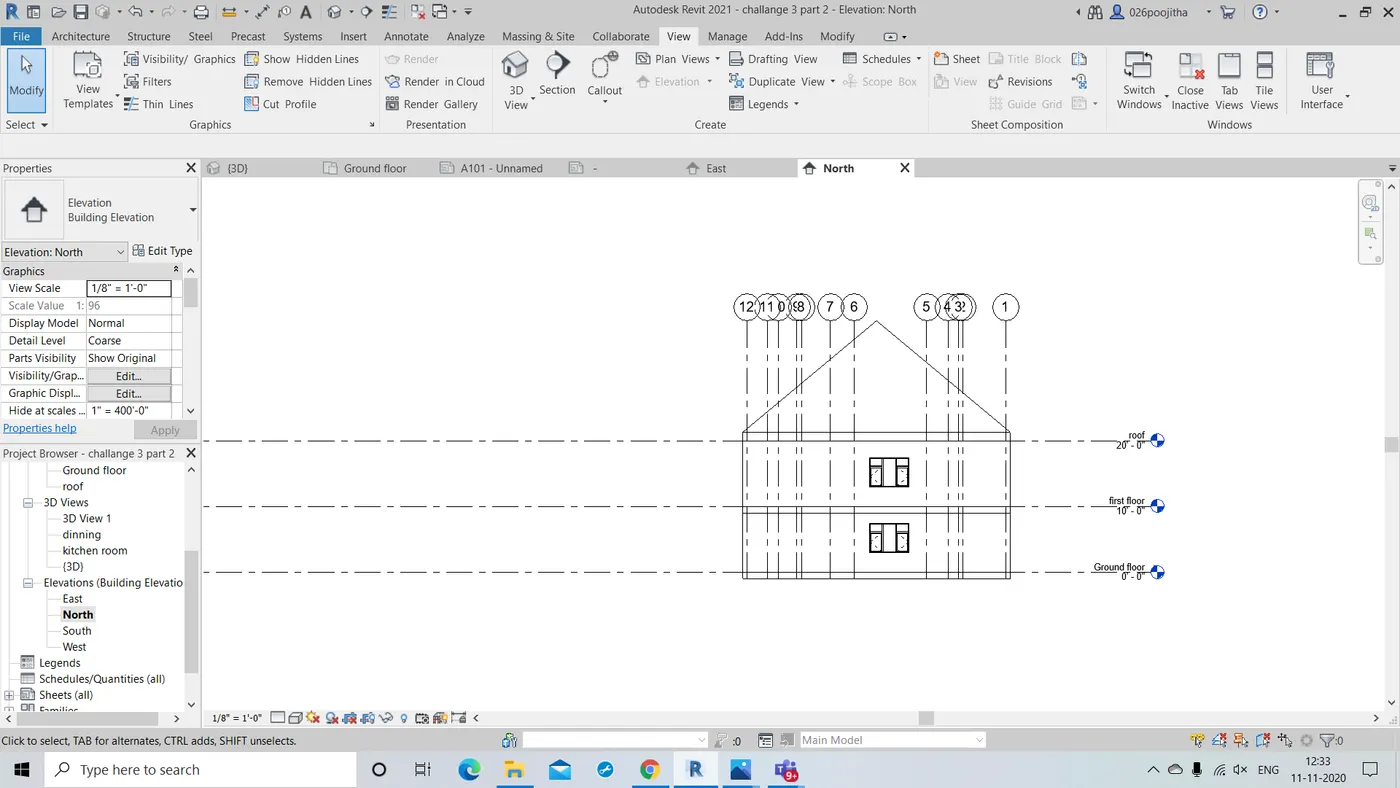
- Tap on the desired view and we get to see that .
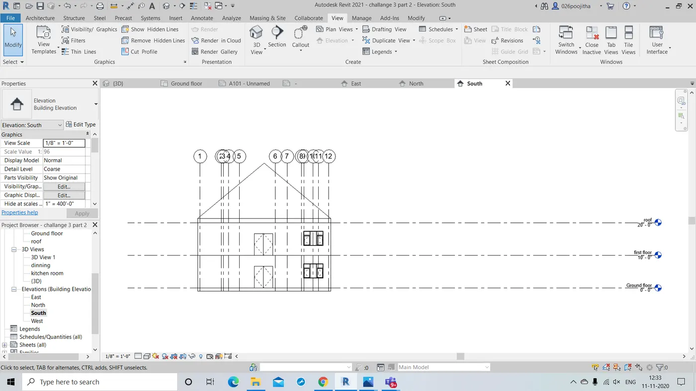
RESULT: By following the above pattern we get to see the different views of the project.
7.Question:Produce section cut through each room either cutting across longitudinally or in a transverse direction.
Ans) AIM:To Produce section cut through each room either cutting across longitudinally or in a transverse direction.
TOOLS REQUIRED:
View -> section
Project browser.
PROCEDURE:
- First open the project that you wanted to have section.
- Now go to the view tab and select the section option.
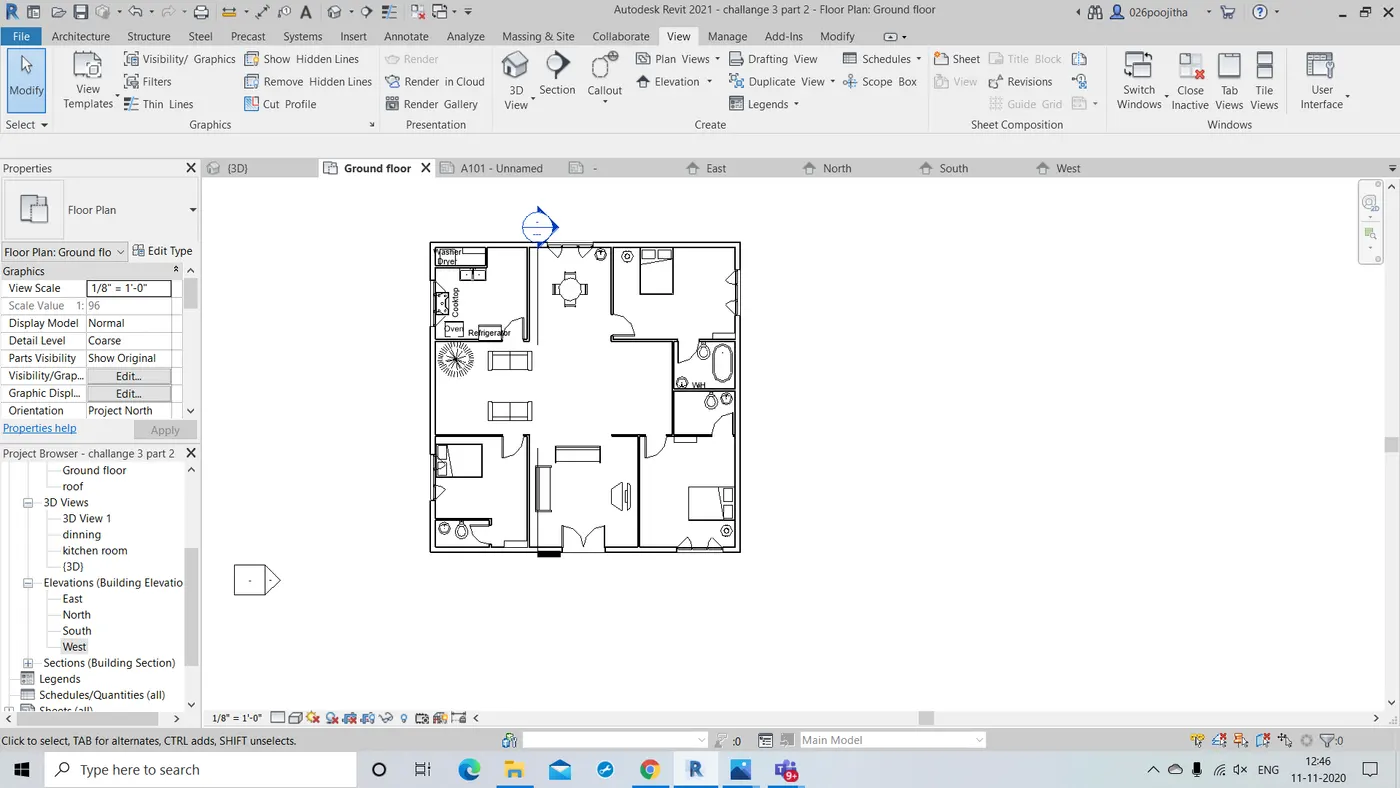
- Now place the cursor on the project where you are intrested to make the section.
- After that place the cursor at the end point to indicate the closing of the section part.
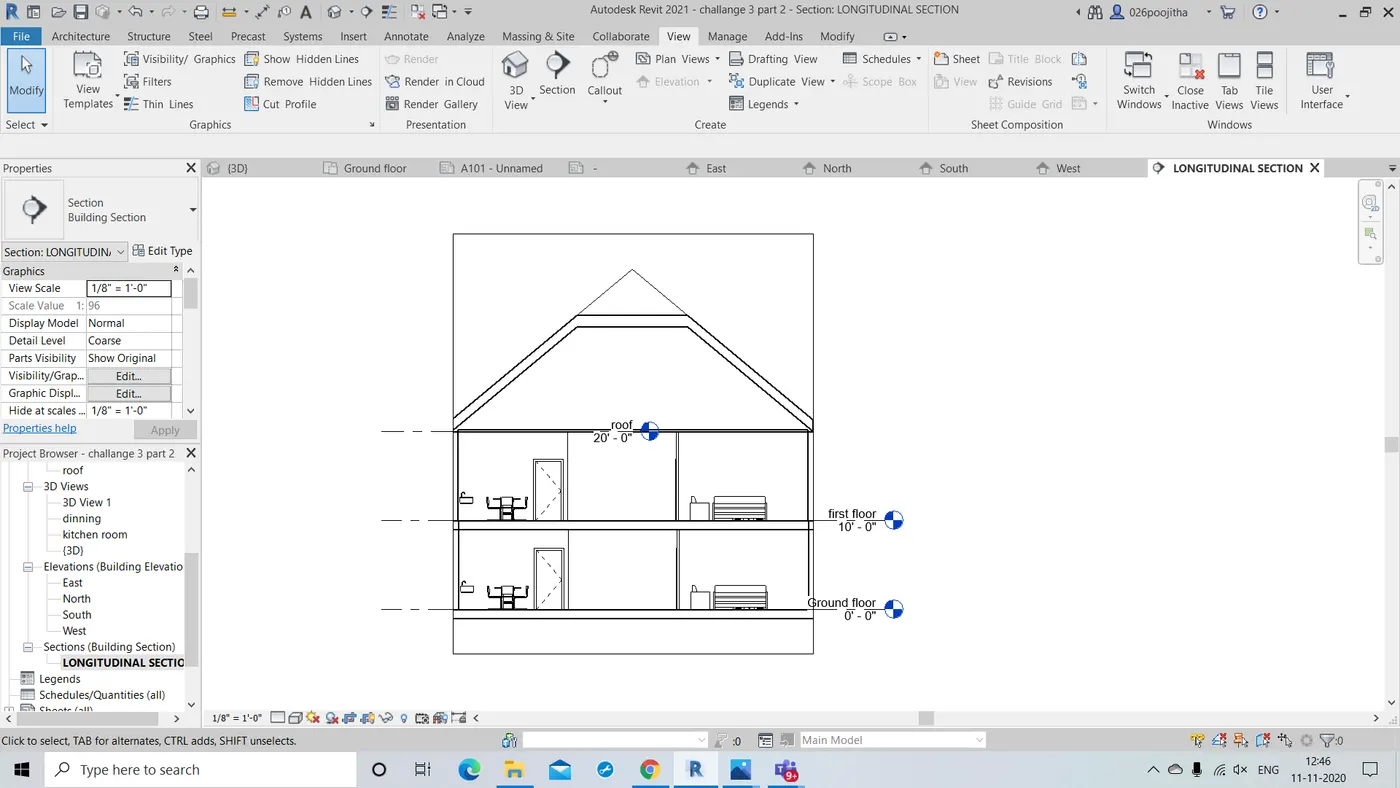
- Draw the line vertically if you wanted a longitudinal section.
- Draw the line horizontally if you wanted a transverse section.
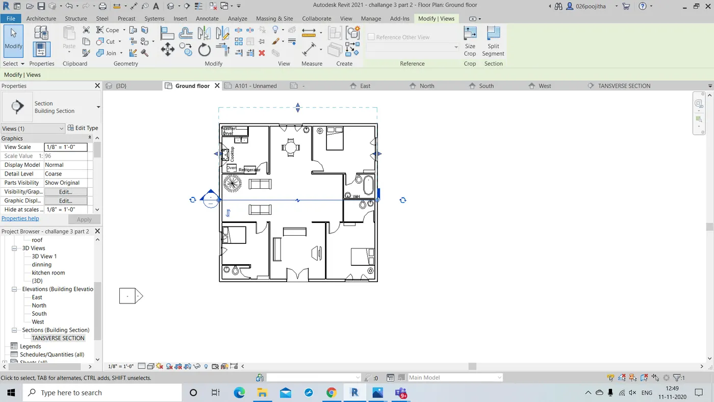
RESULT: Hence the section is created in the desired way by following the above steps.
8.Question:Classify the views , Plan Views, Section Views and Elevation views to either Design or Documentation category using Properties browser.
Ans) Viewing of an image or an object takes place in many ways such as 2D ,3D and many more some among them are:
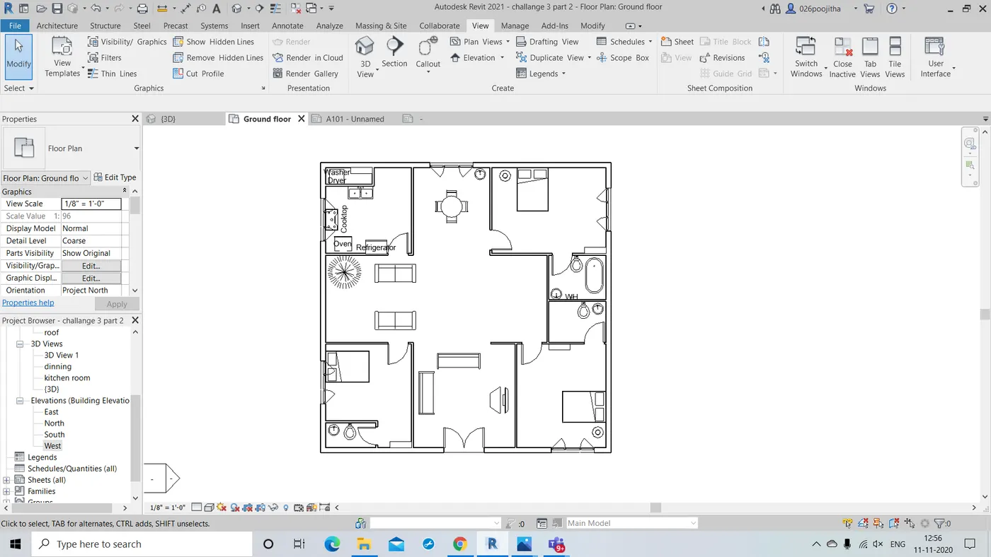
PLAN VIEW: It is the top view of the horizontal cross section of any design.The plan view will establish the layout of the walls, doors, windows, etc.The image of the project lies in the X-Y plane.Even a normal person who doesn't have knowledge about the construction can understand the plan view.The plan view is used by designers and architects to produce finish schedules and the majority of the architectural features of a project. Even the structural engineer will use a plan view of the project to show the footings, foundation walls and the slab on grade. The majority of the plans in a full construction set of documents is in plan view.
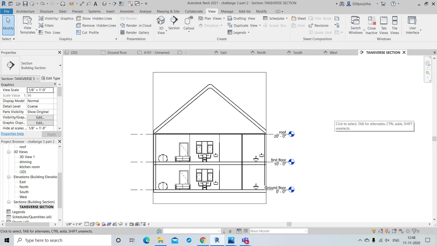
SECTION VIEW:It is the view which is obtained when a project is cut or seen through.That is when we wanted to know about the inner aspects or the interior of the project. Here we cut the section part the we desired to see in through and we can have a clear look at the things that aren't seen through the 3D view.They help civil engineers, architects, and airplane designers communicate their ideas to their peers.Sectional views reveal hidden details in a mechanical drawing.
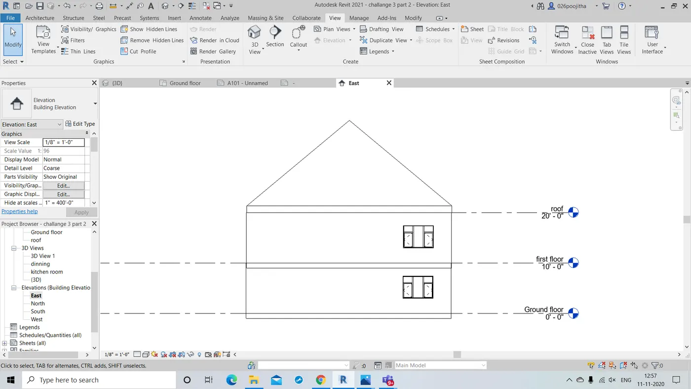
ELEVATION ViEW:It is the front view of the vertical cross section of any design.Elevations are essential in kitchen design, as well as other detailed renovations. Without elevation drawings, you cannot see the details of your new cabinetry, the size of each drawer or the location of each cabinet. A floor plan simply cannot communicate all of this information adequately.With view particularly view all the four sides of the building and know about the details.
9.Question:Using the sheet template produced create multiple sheets as follows
a. A 101 – Ground Floor Architecture Plan
b. A 102- First Floor Architecture Plan
c. A 103- Roof Plan
d. S 101- Ground Floor Structural Plan
e. S 102 – First Floor Structural Plan
f. S 103- Roof Framing Plan
g. A-201 – North South Elevations
h. A-202- East West Elevations
Ans)AIM: to create the multiple sheets as following.
TOOLS REQUIRED:
View -> sheets
properties -> graphics
Insert -> image
PROCEDURE:
- Firstly open the view tab and click on the sheets.
- A new dialog box opens and we need to select the desired type of sheet.
- Now clicking on the a new sheet opens with default naming .
- We can change the names with the help of properties drop down or by just clicking on the particular place itself.
- Now name the sheet as A101 and place the ground floor plan picture there.
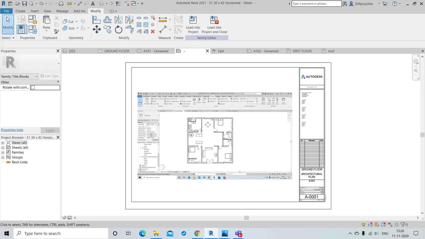
- Name the another sheet as A102 and place the first floor plan there.
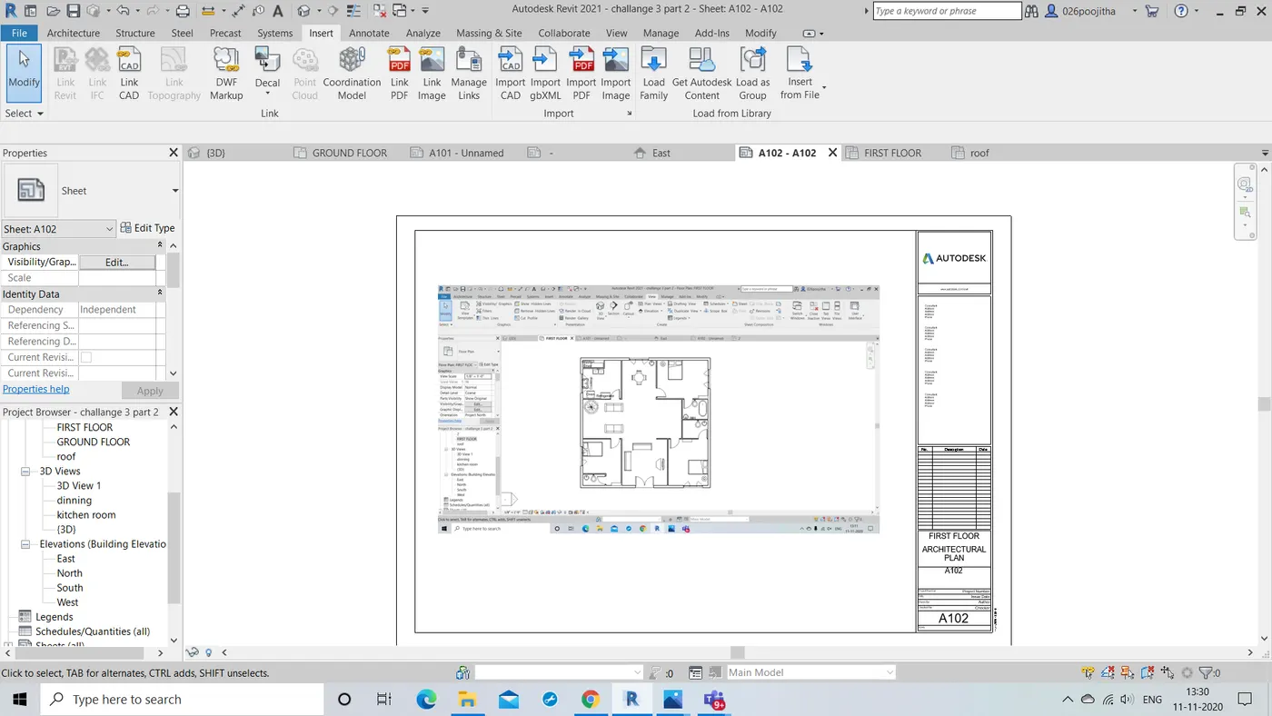
- Name the next sheet as A103 and place the roof plan there.
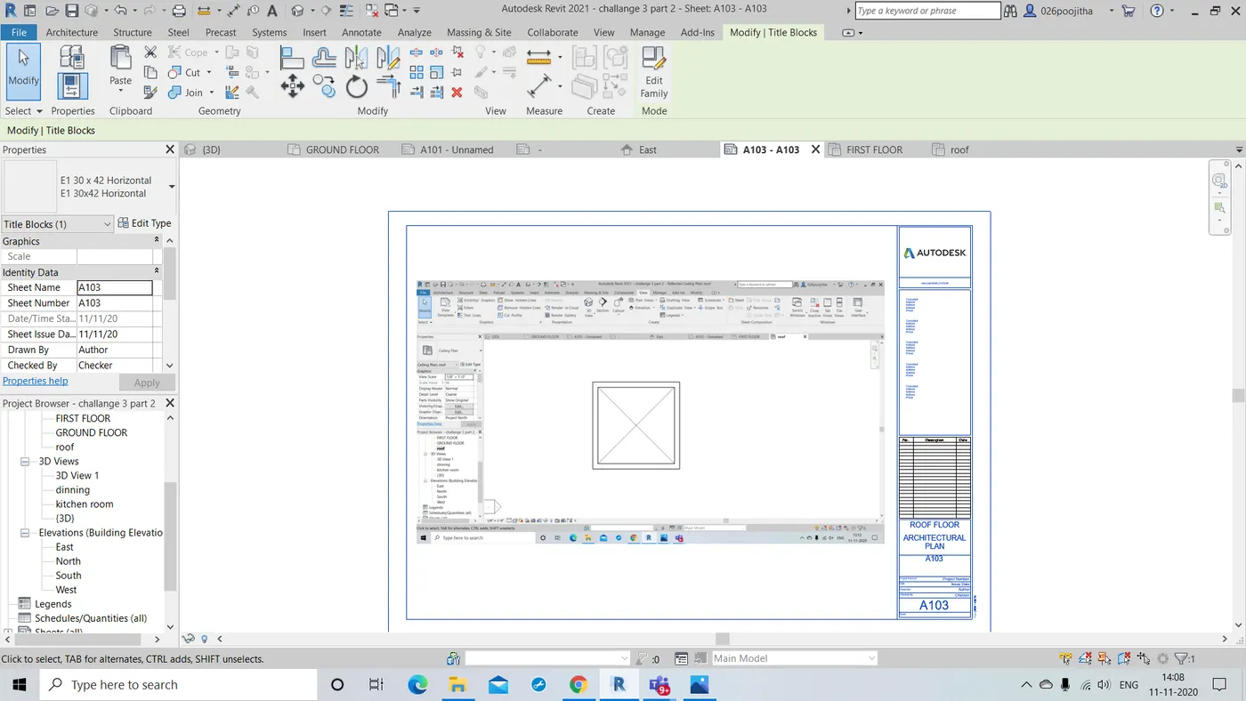
- Name the next sheet as A201 and the place the North South elevation plan there.
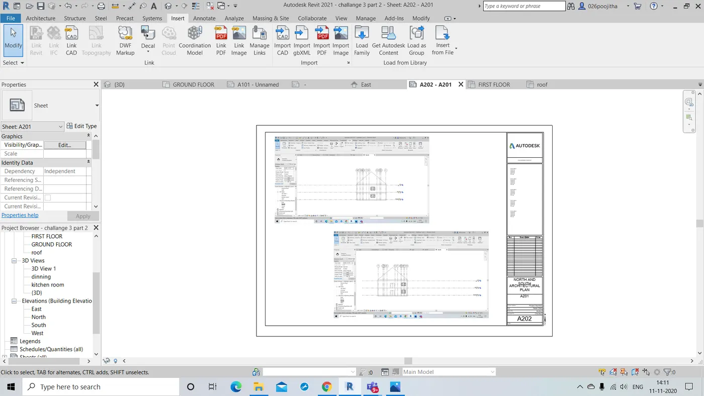
- Name the next sheet as A202 and place the East West elevation plan there.
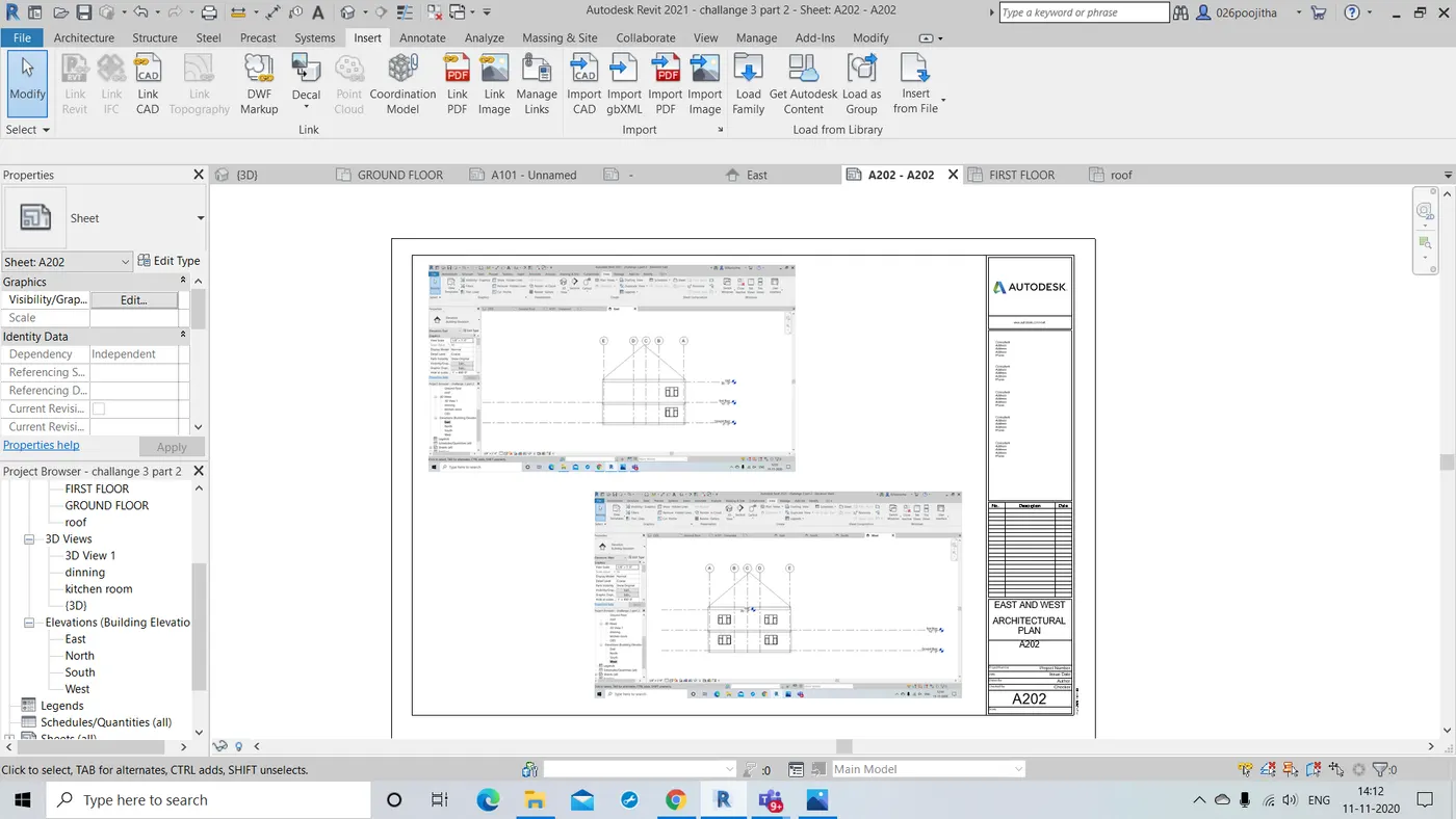
RESULT: With the help of these sheet name we can identify and place the different plans in different sheets with correct parameters.
NOTE: Structural plans aren't explained in this week session.
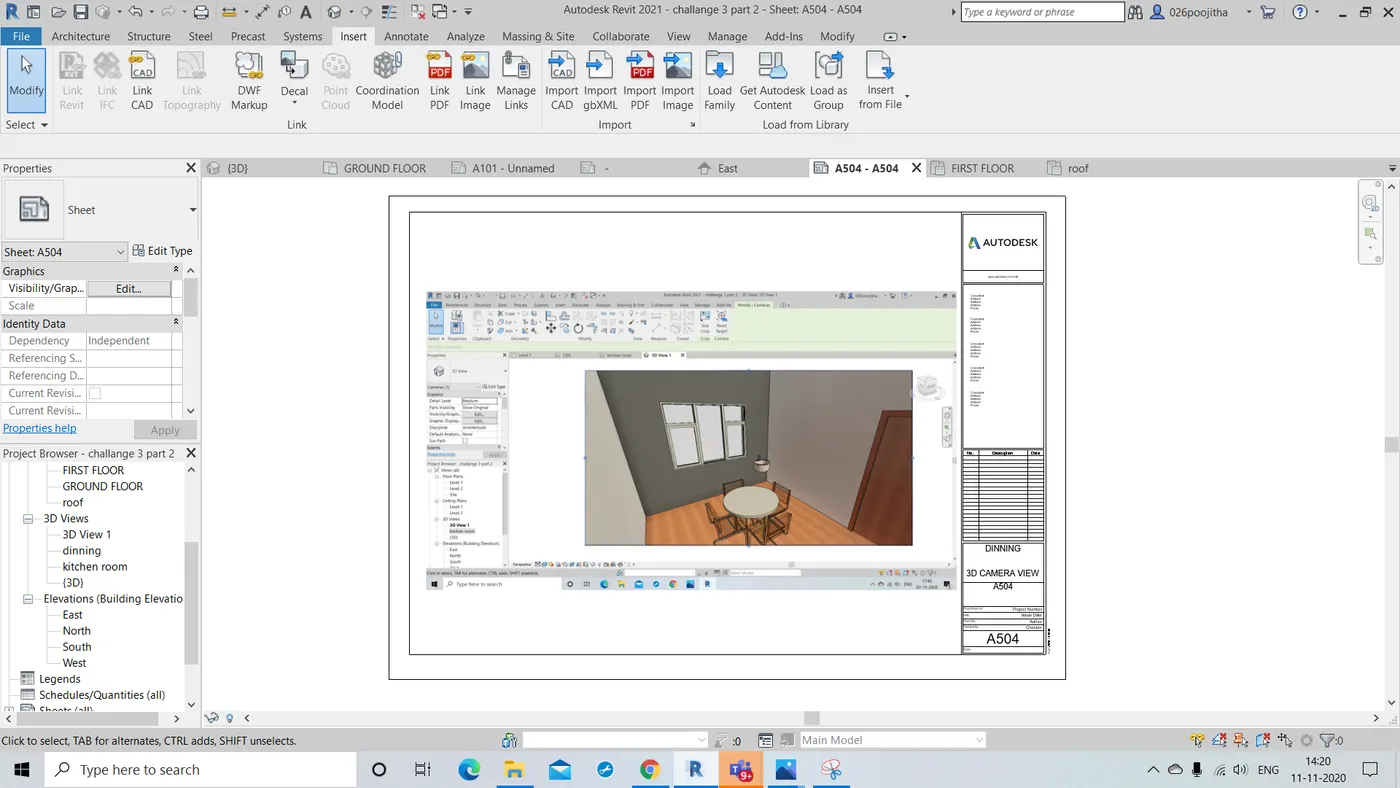
10.Question:Create a camera specific view or a 3D view in each room ( living, dining, bed room ) . Based on the views create new set of sheets starting A-501 (you can add as many sheets after , 502, 503.. n)to place the 3D view images.Produce the sheets as a part of project drafting.
Ans) AIM:To create a 3D camera view of each room and place them in different sheets and name the appropriately.
TOOLS REQUIRED:
view -> 3D view -> camera , sheets
properties drop down -> graphics
PROCEDURE:
- Select the project in which you wanted to show the 3D view.
- Now select the 3D camera view option in the view tool bar.
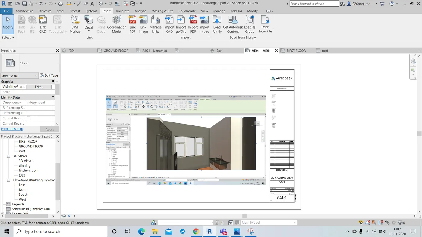
- Now place the camera so that maximum area of the room is covered to have maximum coverage.
- To get the room picture even more accurately extend the lines at the corner to have the prefect view.
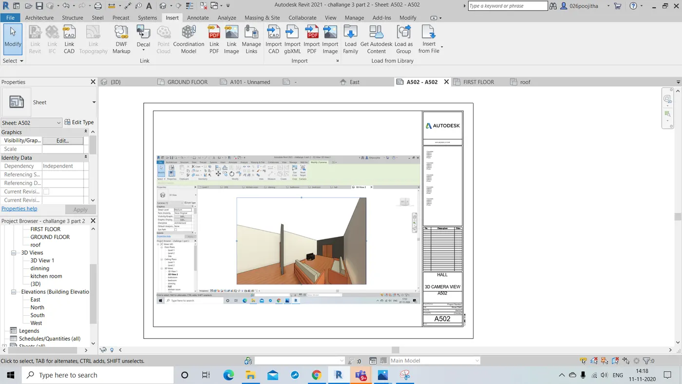
- Now select the sheet option and change the parametres accordingly
- Later place the desired room 3D camera view of the project in the sheets and name them accordingly.
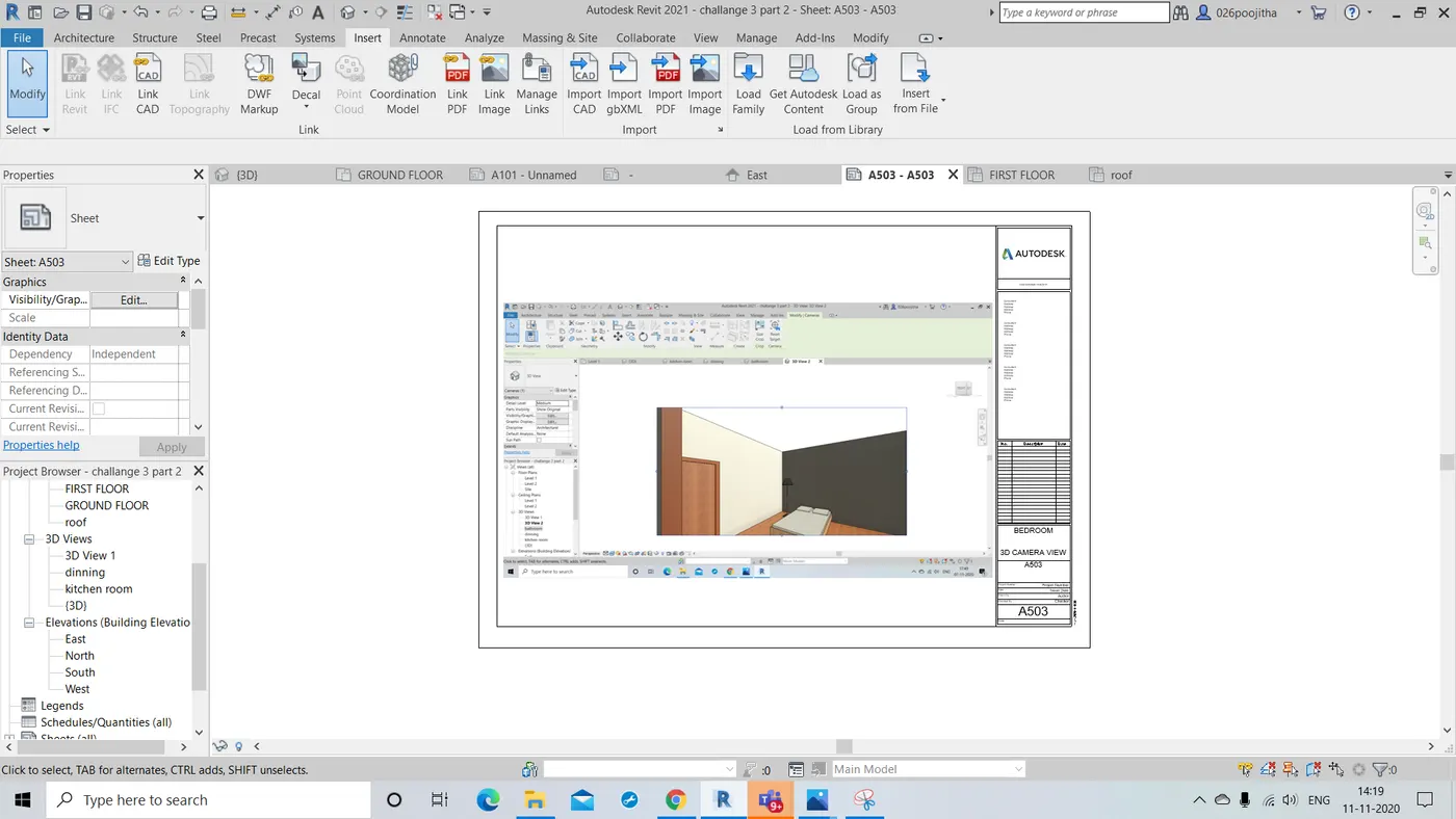
RESULT: Hence the sepearate sheets are created and named in a organised way.