REVIT_Usage of Elements and Properties_Week 3
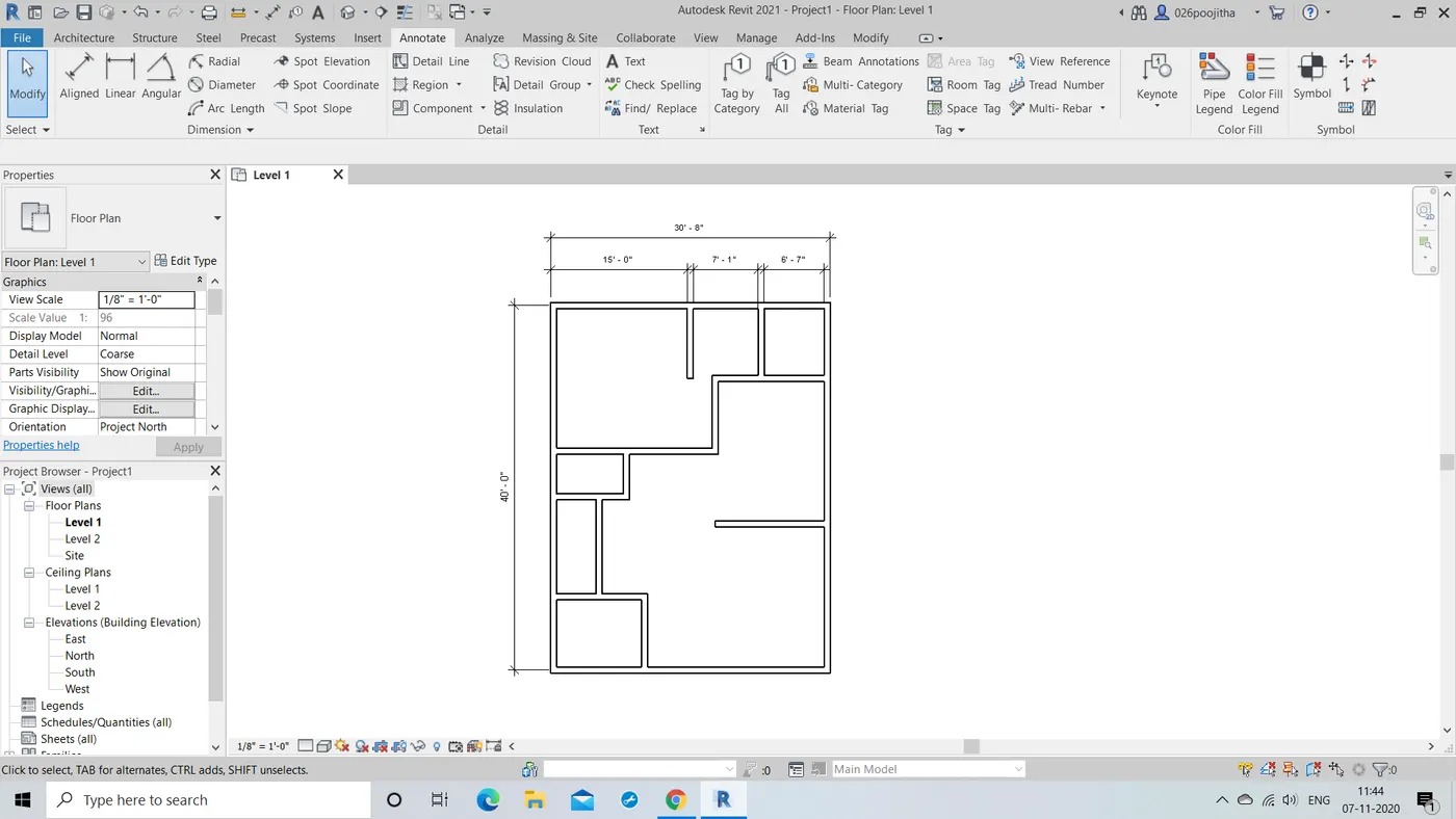
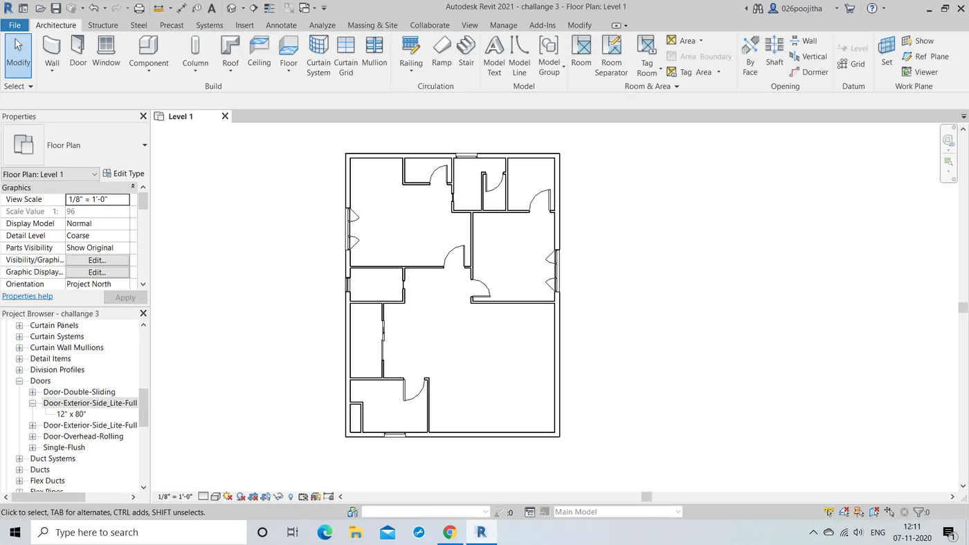
1.AIM:To add floor using floor option in architectural tab, set the thickness also draw to grids for the ground floor plan.
TOOLS USED:
architecture tool -> floors, girds, levels.
properties -> edit tool.
PROCEDURE:
- Firstly open the previous project or draw a new residential layout.
- By selecting architecture menu we can change the size of the wall .
- Now select the floor option from the achitecture tool bar and you will be directed to manage tool bar there select the pick line option to make your task easier.
- After selecting the lines check the loop is closed or not ,if closed click the tick mark available there.
- Henece the floor is created.
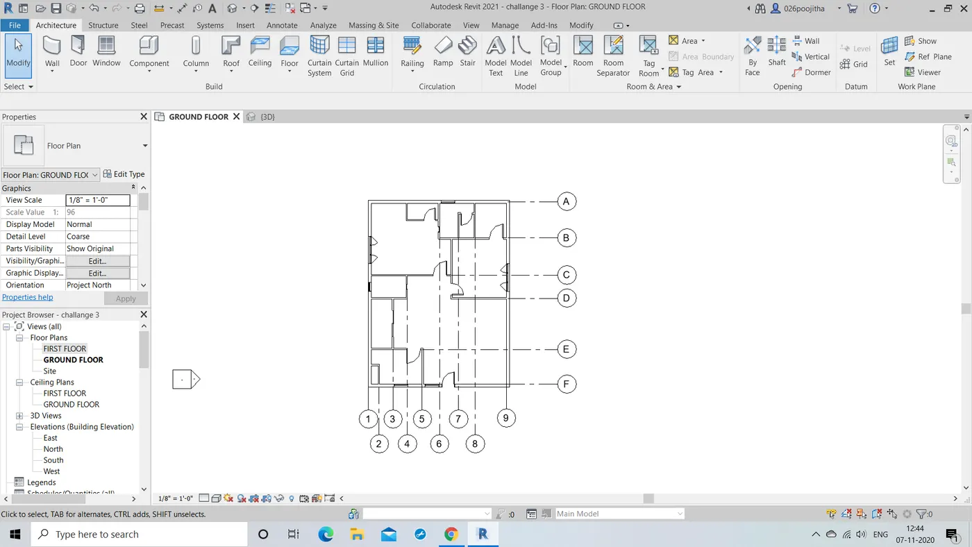
- Now to draw grids select the option from arcgitectural tool bar and draw them along the walls.
- As we now the rules that have to be followed such as naming the vertical grid as A,B,C and horizontal as 1,2,3 in the right to left pattern or top to bottom partten respectively.
RESULT:
Hence by doing this the floor for the residential building is obtained and the grids to the ground plan too.
2.AIM: To add walls and modify the boundries of the walls.By selecting appropriate thickness and materials to the wall.
TOOLS REQUIRED:
Properties browser -> level, view.
Defaulty 3D view
Edit type -> duplicate, rename,structure,thickness
PROCEDURE:
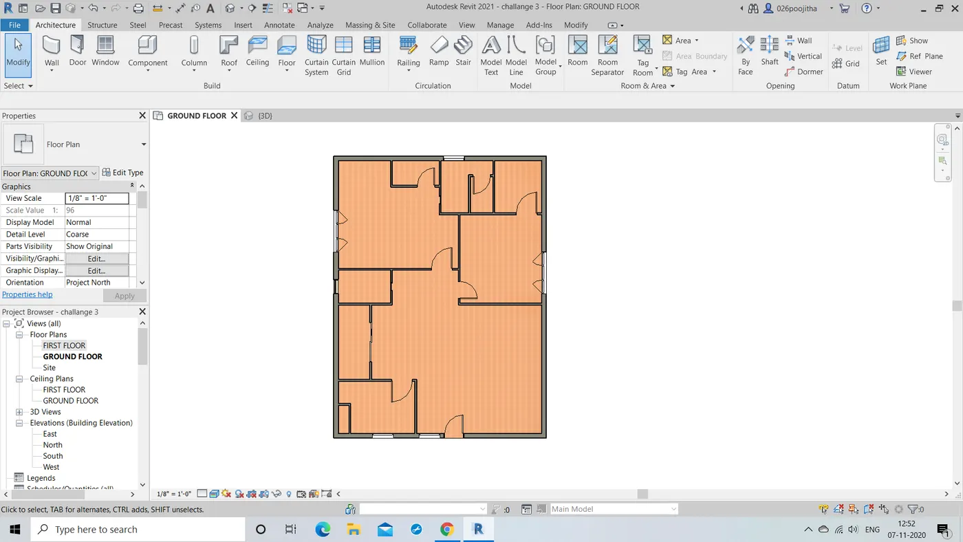
- Firstly select the floor in the ground floor plan.
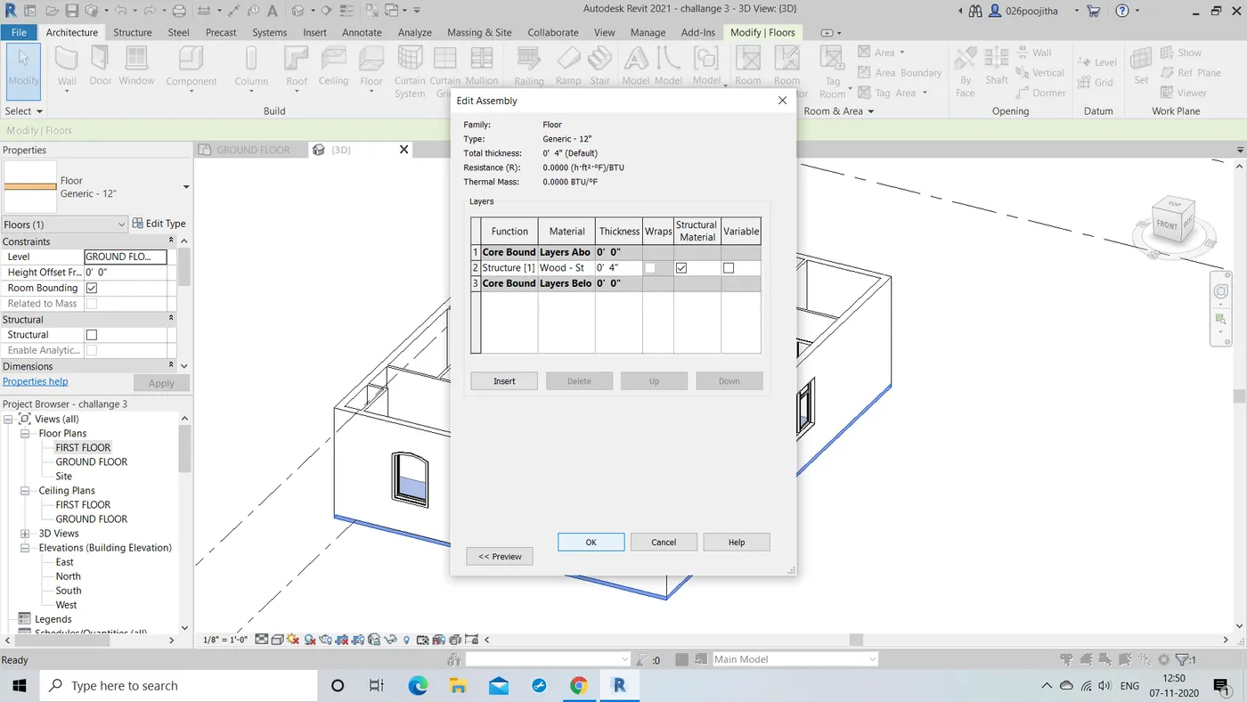
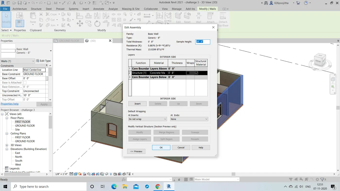
- Now select the properties and choose edit type tool and we are directed to a tool bar where we can find the required dimensions.
- Or else duplicate the desired dimensions by duplicate option and rename the option
- Also select the desired thickness of the floor such as to avoid the problem of overlapping.
- In the same drop down dialog box we can change the structure type by clicking on the structure option for the desired floor type such as cement masonry, wood, marble.
- Now repeat the same procedure to change the wall thickness and the wall structure.
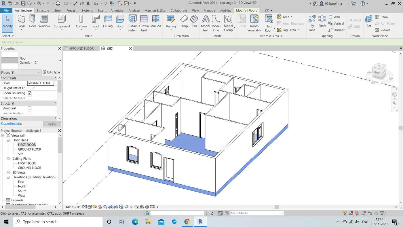
- The thickness of the wall is to be 0' 4" since to avoid over lapping of floor and roof for the further convenice.
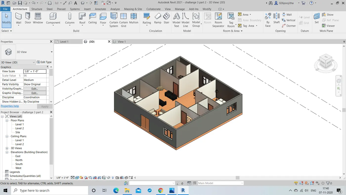
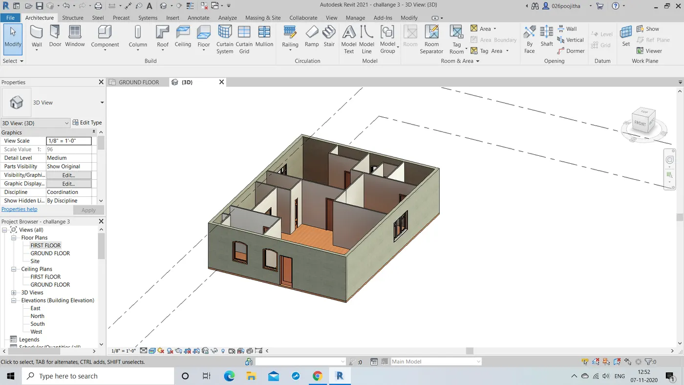
- After changing the floor and wall type check the 3D view of the plan and make the changes accordingly.
RESULT:
Hence walls and floors are modified according to the requirement and also to the desired features are obtained.
FROM MY OBSERVATIONS :
- Connecting walls is a more convenient when we used the " up to level 1 floor".
- Height option is convenient for modelling.
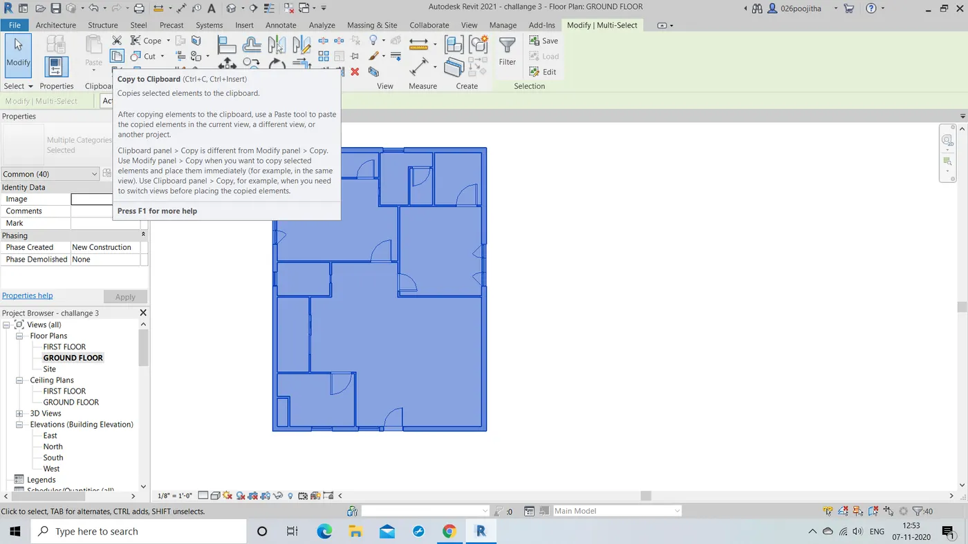
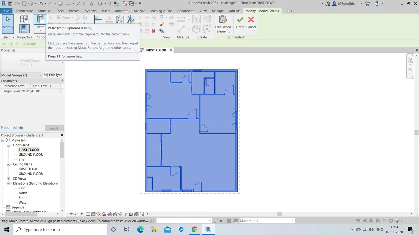
3.AIM:To copy the model elements from the ground floor level to the First floor level using the copy and paste options from modify menu.
TOOLS USED:
properties browser -> level, view.
modify tab -> copy,copy to clipboard,paste, paste from clipboard
PROCEDURE:
- After drawing all the components and making changes in the elements such as floor, wall.
- Now with the help of copy option copy the ground floor plan and copy it in the copy to clipboard option present in the modify tool bar.
- Now go to levels in properties browser and select level 2 and rename it as first floor level.
- now paste the drawing the is copied earlier from clipboard to the first floor level view.
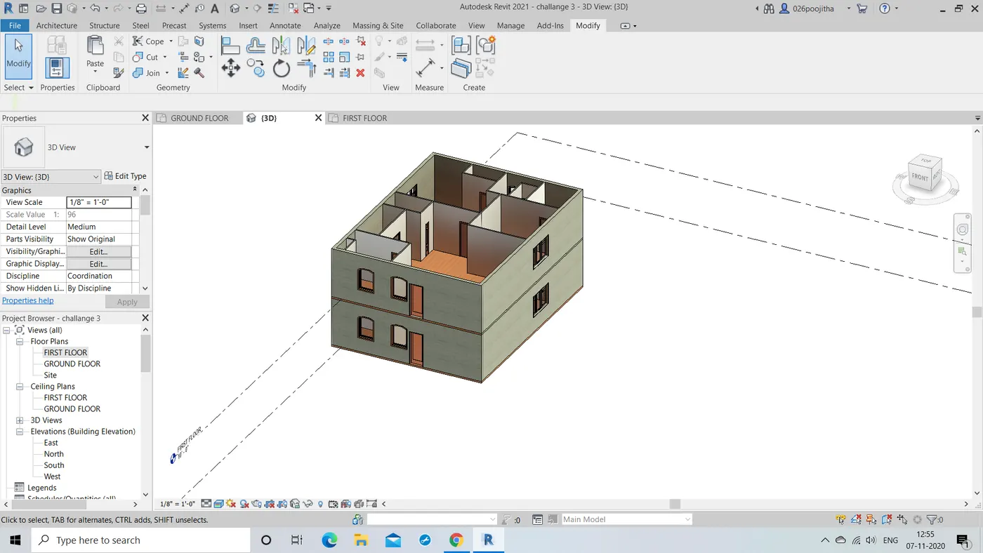
- Now select the default 3D view option from the view tool bar and see the elevation and exterior of the 2 floors in 3D view.
RESULT: Hence by copy and paste options we could obtained the structure from ground floor to first floor successfully.
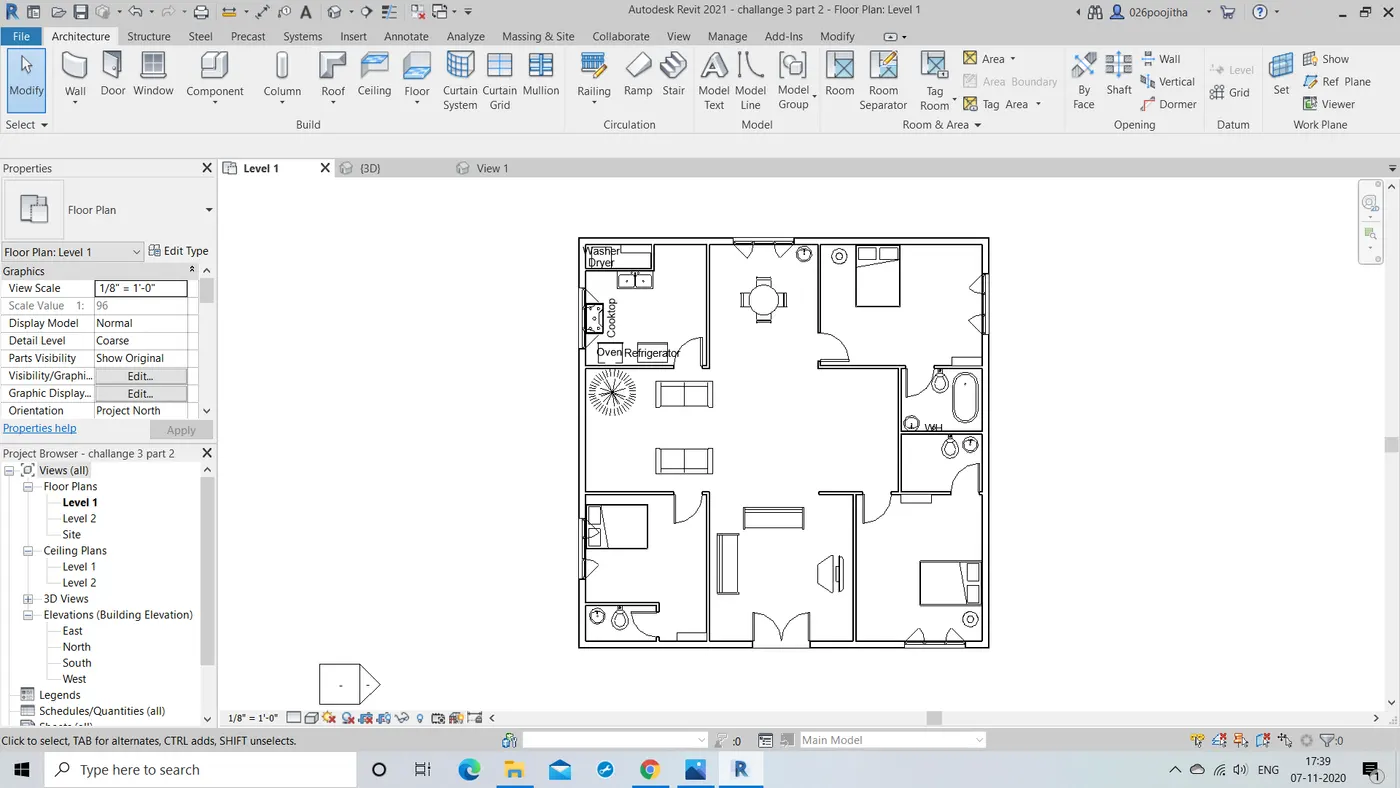
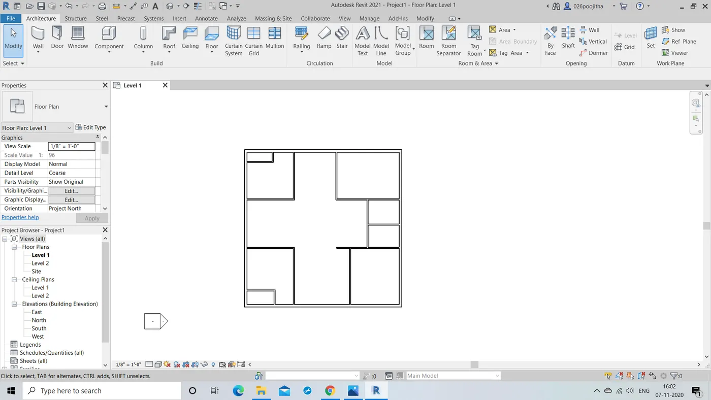
4.AIM: To draw a residential building with the desired exterior and interior walls with required unit specifications.
TOOLS REQUIRED:
Architecture -> wall,room tag, room seperator, floor
properties browser -> edity type
modify tool -> trim
PROCEDURE:
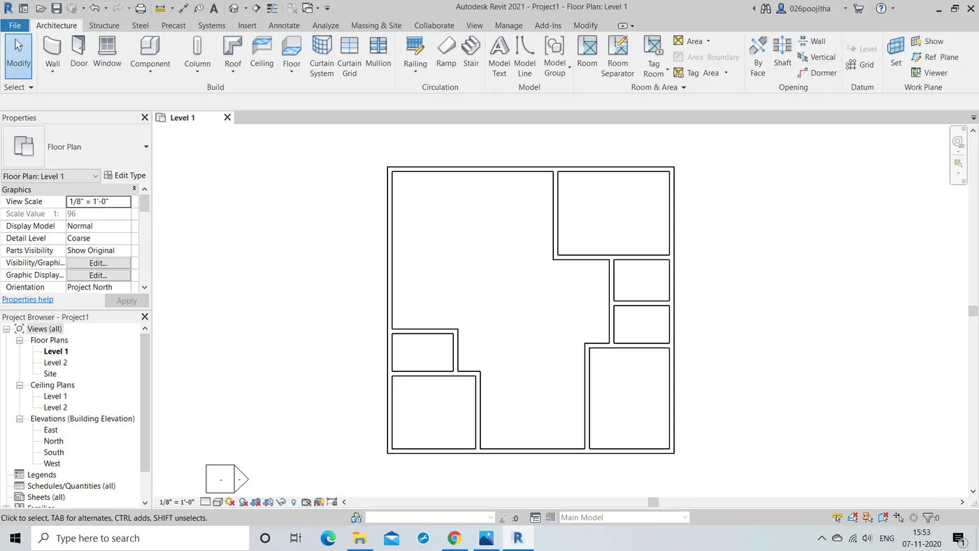
- Firstly open a new project and start drawing the residential building with desired wall thickness so i would like to take the exterior walls as generic 8" and interior 3 1/2" partition wall by use the edit type tool.
- Now after completion of the wall trim the unwanted edges or extention to make the drawing neat and presentable.
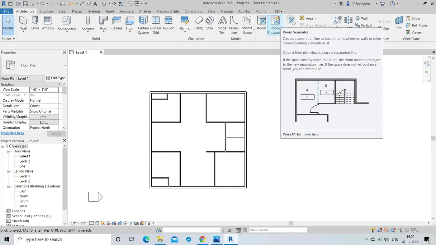
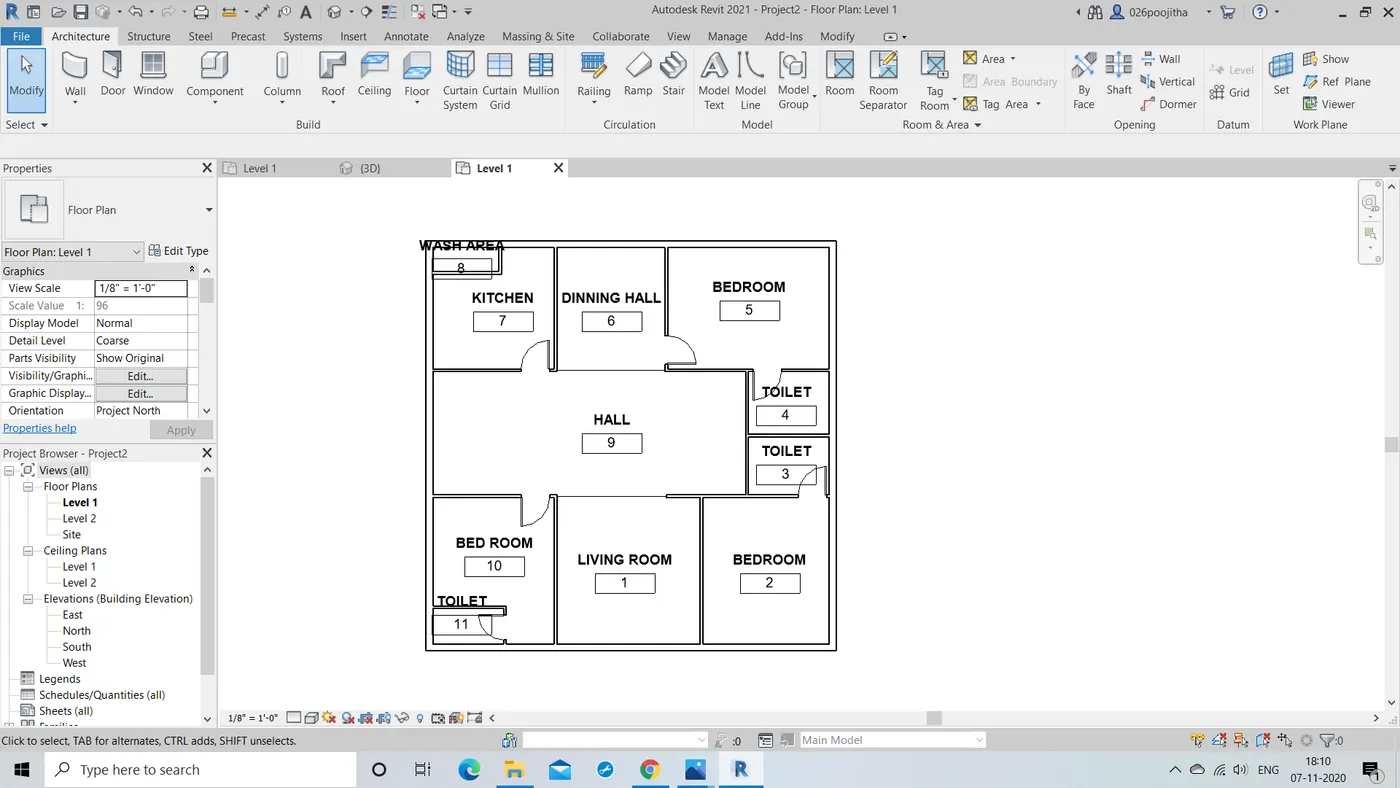
- Using the room seperators and room tags to name them
- Now draw the floor with the thickness of 4" which helps us in further adjustments.
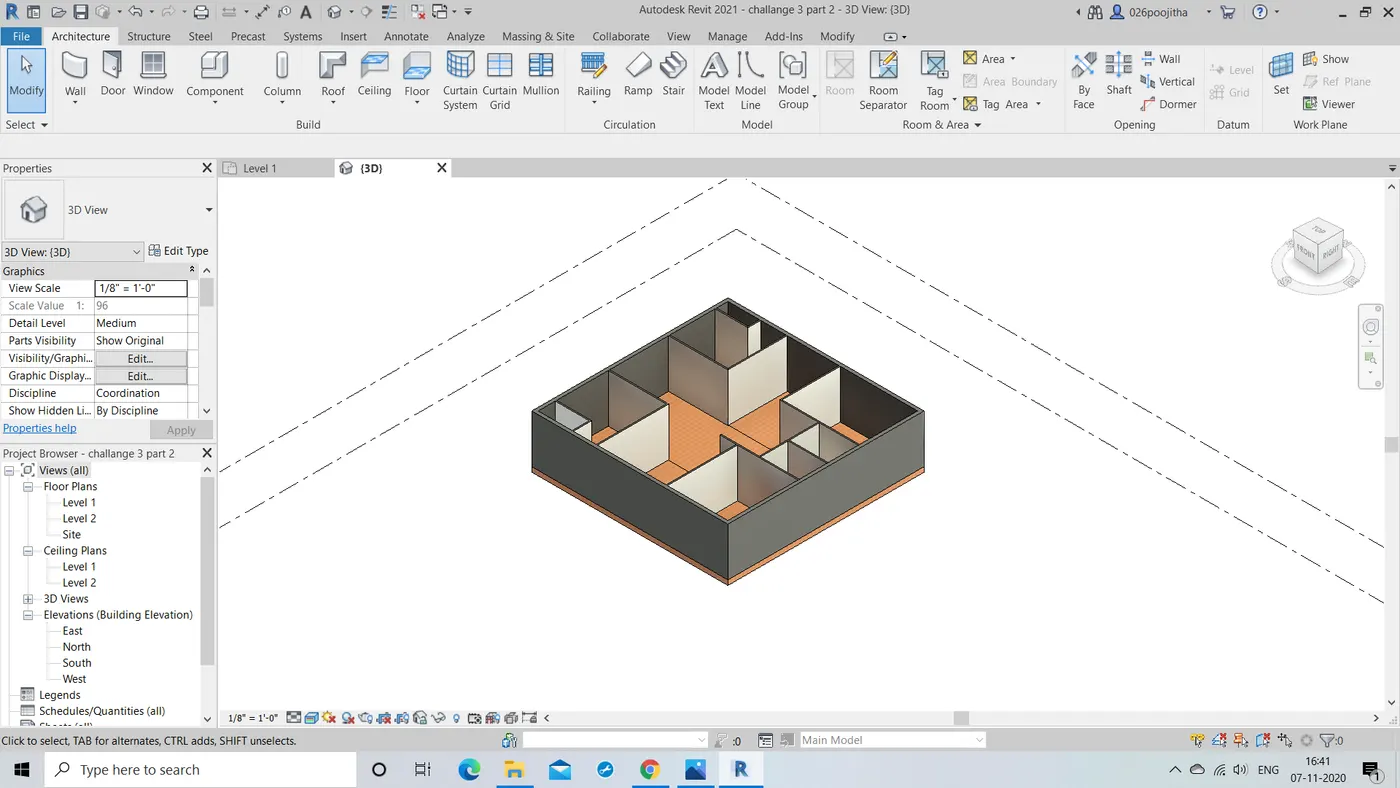
- Change the view style to make it look more realistic.
RESULT:
A residential building with proper walls and floor is obtained by following method.
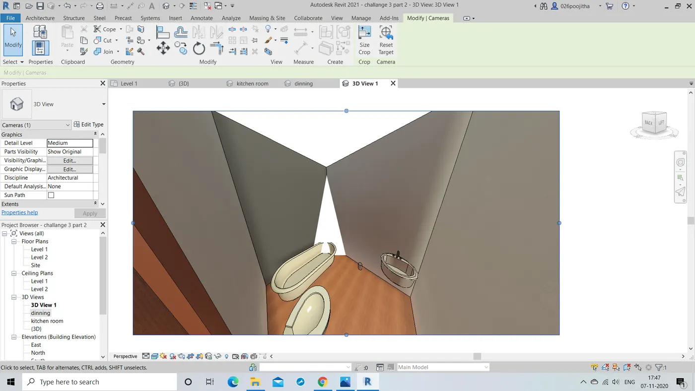
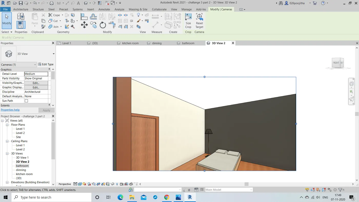
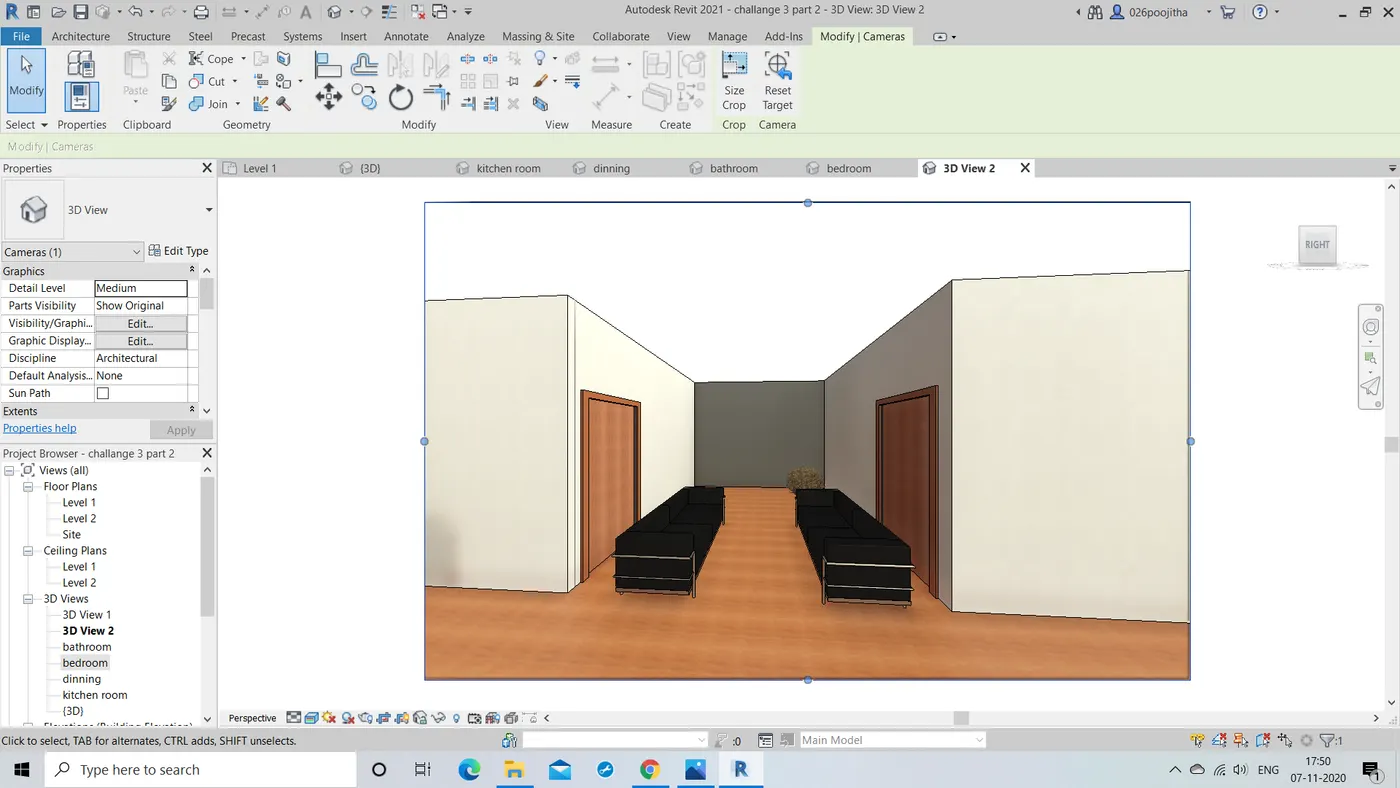
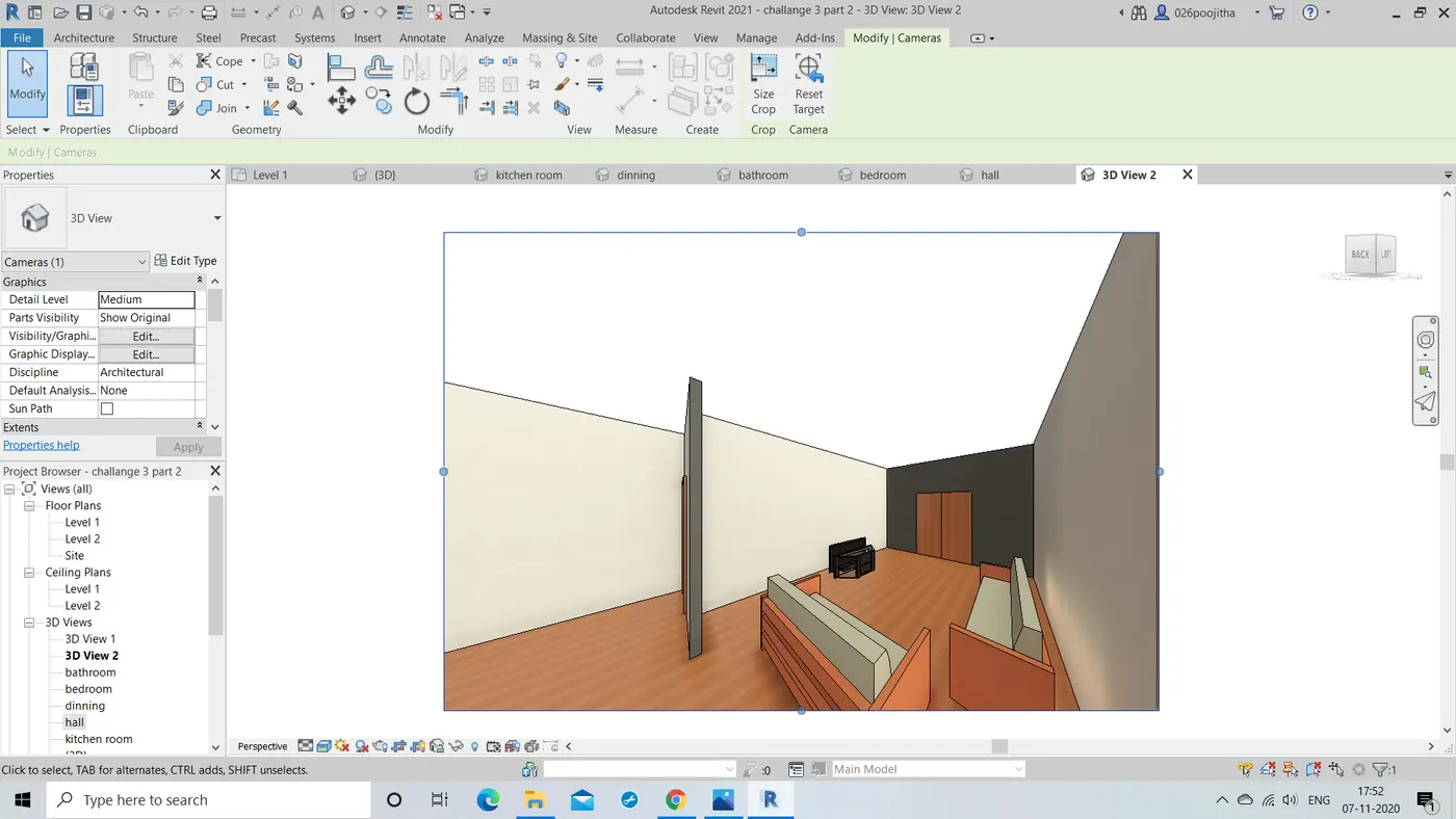
5. AIM: To included the residential components . Place these components in appropriate locations to add details to your residential model
a. Place Doors and windows in the wall at appropriate locations
b. The Living Room must include furniture set, couch table and TV desk and shelf cabinets
c. The Dining Room must include a table and chairs serving the purpose of eating
d. Bed Room must include a bed set, shelf, lighting and individual study desk and chair
e. Rest room should include bath tub and plumbing fixtures discussed in class
f. Kitchen should include countertops, gas stove cabinet and shelves to store food items
g. The wash/storage room can include washing machines and shelves to store clothes
TOOLS REQUIRED:
Insert -> revit families, libraries,load family
View -> defaulty 3D view, camera
architecture -> doors, windows, components
modify -> move, rotate.
PROCEDURE:
- Firstly select the insert menu and click on the load families to load the desired content.
- So to get them we need to download the revit 2021 conent from the google which indeed helpful for the interior modifications
- Now click on the windows icon to load the desired window and its is the same case when it comes to downloading the content.
- Now with the help of roatate and move option present under modify tool,we can place the objects in the desired direction.
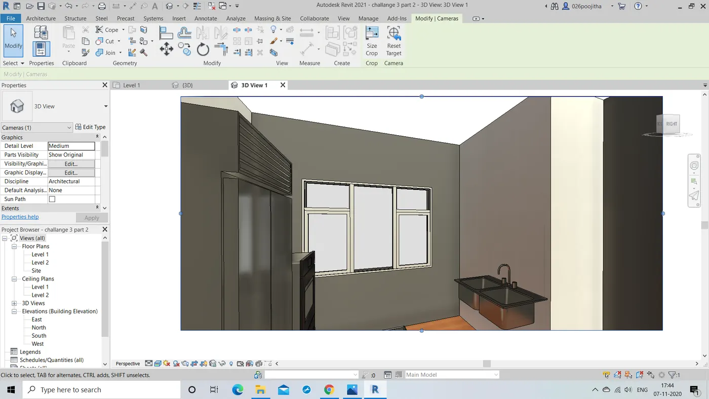
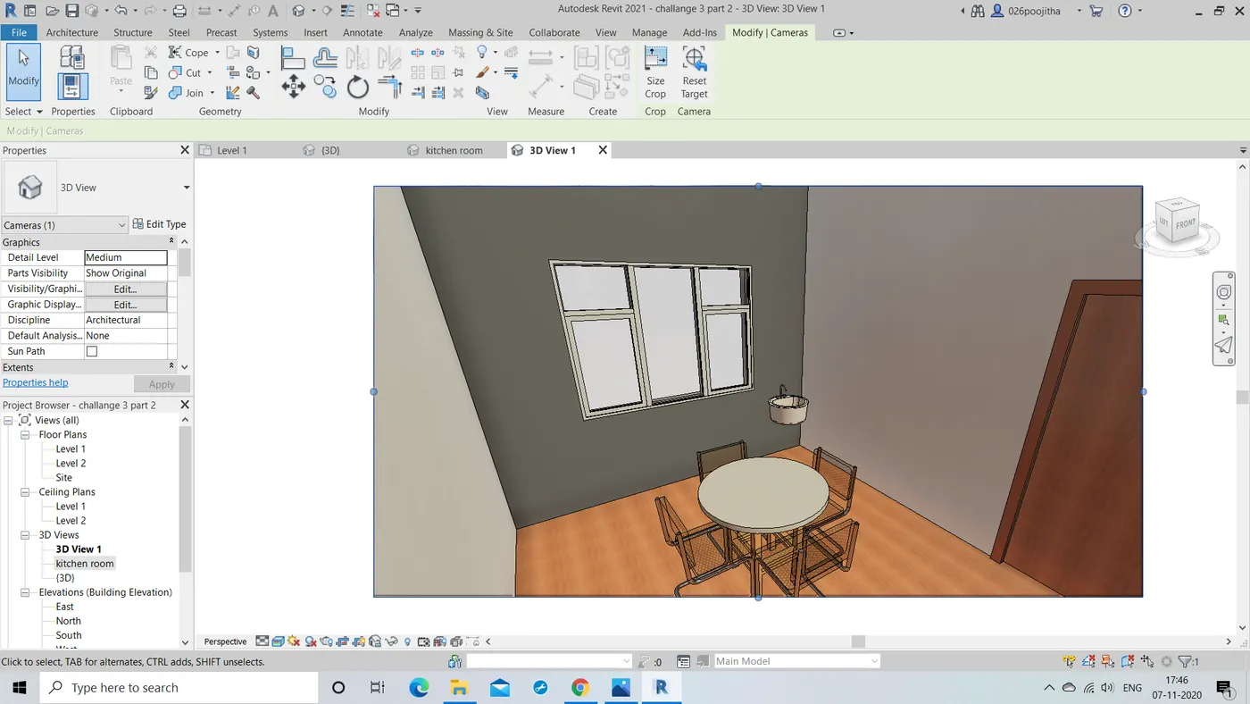
- now click on the camera view present under view option to navigate along the rooms and see the detailing.
RESULT:
Hence by following the above procedure we can obtained a furnished residential building.