REVIT_Creation of basic Drawing_Week2
1. BIM is a 3D modelling software which helps us in understanding and executing the project. It is an effective software that is mostly used for drafting and planning.BIM stands for Building Information Modelling. This software is adduce by autodesk.Provides greater project insight for cost, schedule, and constructability. BIM is classified into:
- Coordination: This is highly achievable by BIM as it supports the system of multiple working in single project concurrently. Hence work becomes more efficient and accurate when a particular sector of people are give their own task which makes their more simple and easier.
- Computation: Calculations and schedule planning are done here where in we can evaluate the energy consumption done while the project is under development also the load bearing capacity while steel designing and many more. Material schedule and quantity schedule are also the advantages of computation.
BENIFITS OF CHOOSING BIM OVER 2D CAD TOOLS:
- CAD involves line- to-line designs where BIM focuses on parameters to design full 3D models.
- In BIM all lines are connected in the model which makes it easy to make any modifications.
- Also in BIM there is a synchronization between all the drawings such as plans, elevations, sections etc. Since all these drawings are extracted from one BIM model, any change in the design of 3D model will automatically result in the updating in all the drawings that are extracted such as making changes in 2D accordingly.
- BIM models are information rich, they provide details about schedules, manufacture’s details etc. This also saves a lot of time since everything that is required with regards to the construction can be extracted from the BIM model itself.
2.Brief understanding of the following terminology:
Category: Revit components generally fall into the categories of loadable components,pipe fitting,lighting fixtures.
Family: A group of 2D and 3D information which is indeed helpful for designing the models.
Elements: They are controlled and defined by the families.
Instances: Individual elements placed in revit which are available after installing the families.
AIM: To select a category,pick a family and element.
TOOLS REQUIRED:
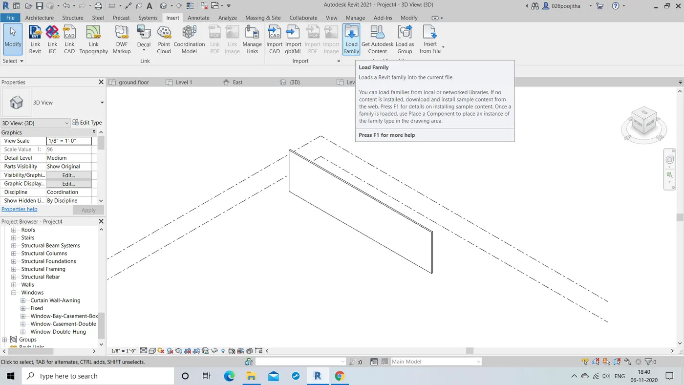
insert tab, load family icon, file name icon, open icon
PROCEDURE:
- Firstly open revit and select the architectural template.
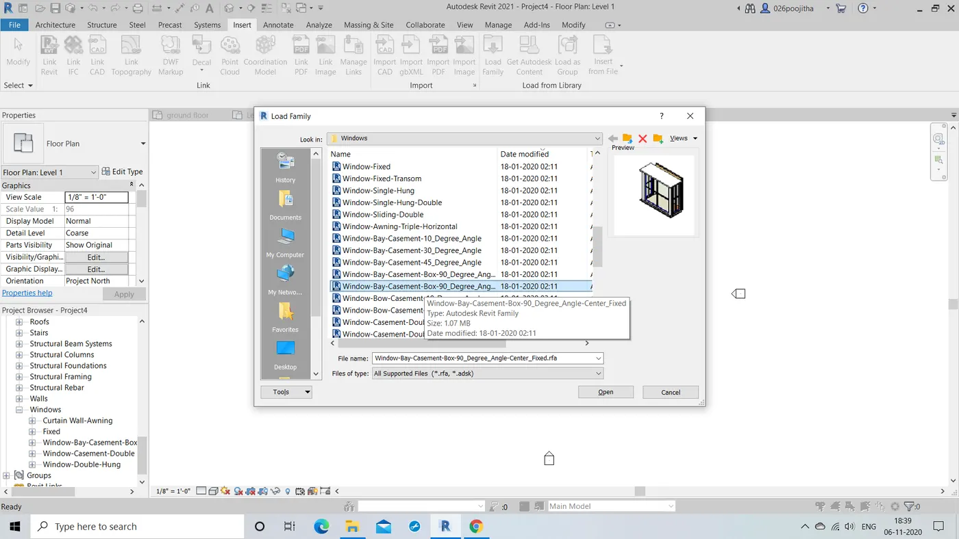
- Click on the insert menu, now select load family option.
- Then load family dialog box appears, now select the desired components.
- Click open.
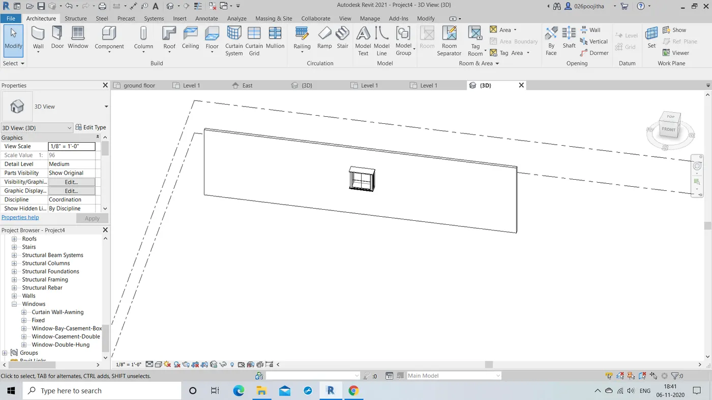
- Now go to the window in architecture menu, select the desired object.
- Now drag and click to the desired location that you wish to insert.
RESULT:
With the help of the above steps we can use families and components in our project.
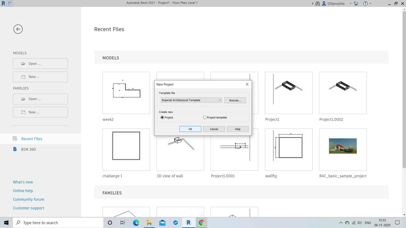
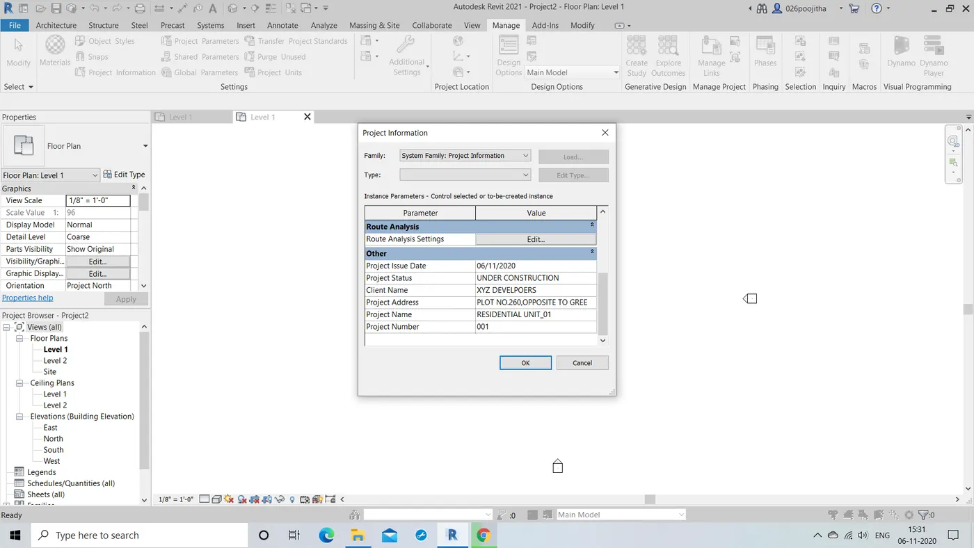
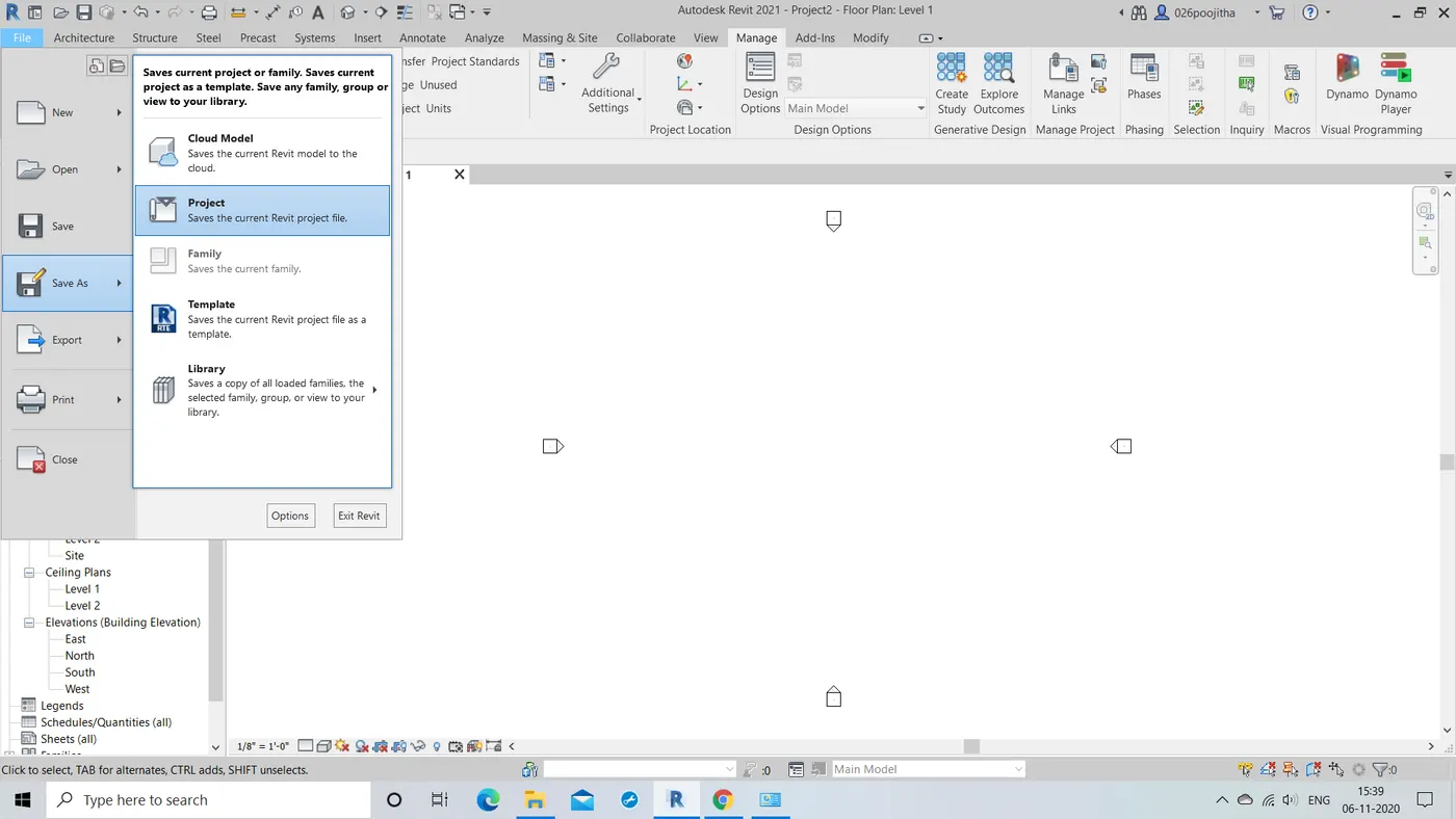
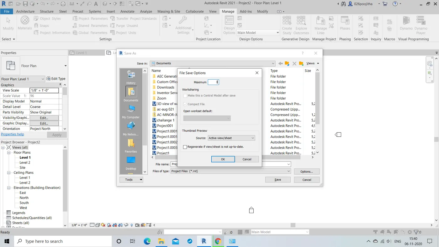
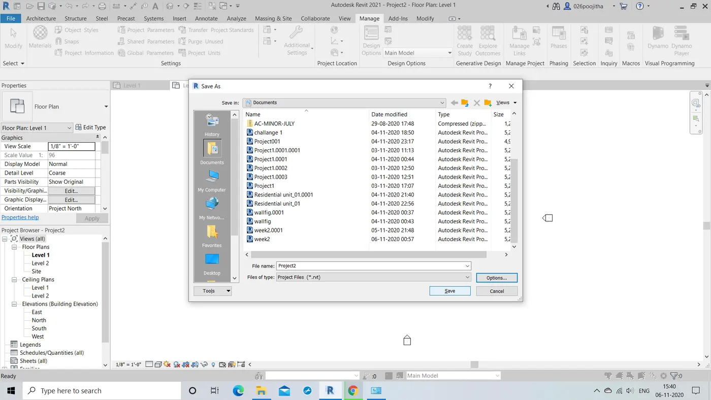
3.AIM: To open a project file with architectural template. Save the file with appropriate name. Complete the project information.Set up the maximum backups for project file to 3
TOOLS REQUIRED:
New icon,save as icon, manage icon,project information icon,project units icon
PROCEDURE:
- Firstly select architectural template and click ok.
- Click on file menu and select save as option and click on project.
- Now save as dialog box appears,give appropriate name to the project and save it.
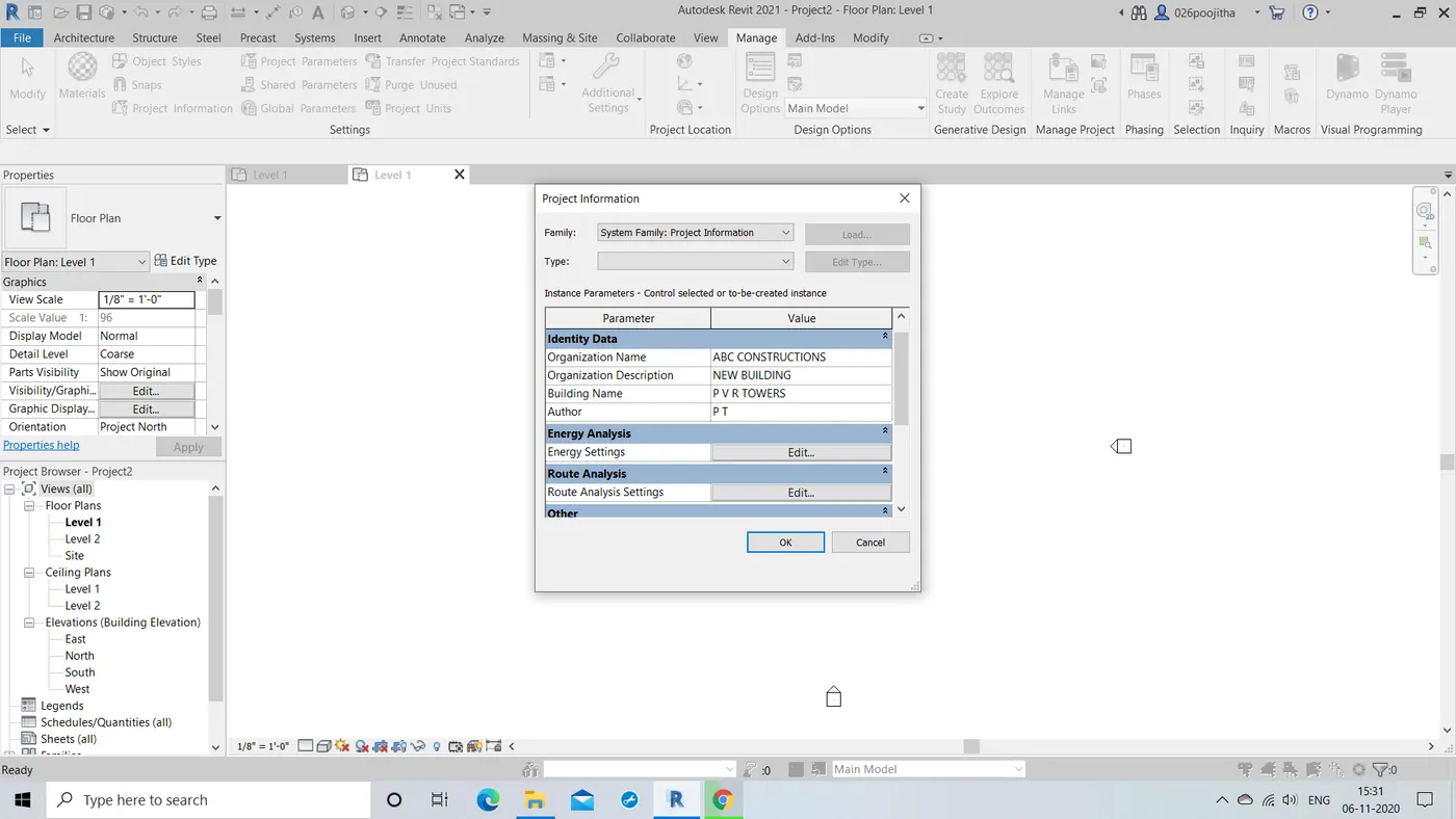
- Now click on the manage icon and click on project information icon which is present inside this and fill the essential information required .
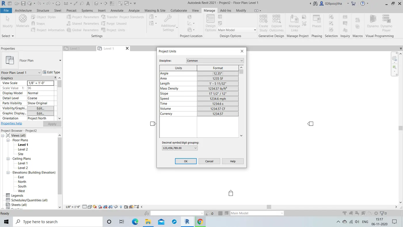
- Later in the same manage tool bar we can change the units to imperial or metric as per our requirements.
- Finally set the maximum backups to 3.
RESULT:
We can open a project in architectural template and save it with the desired name also having 3 backups to the project.Also can add on project information and project unit.
4.Levels: levels in revit are used to represent the floor in elevation.
Grids: They are used to represent all the walls with the help of horizontal and vertical lines with the help of notation. where in the horizontal naming starts form left to right and vertical naming starts form top to bottom.
AIM: To create the following levels in the revit software.
Ground Floor @ 0’
First Floor @ 10’
Second Floor @ 20’
Roof @ 30’
Grids Transverse Grids A, B,C,D, E @ 10’ spacing
Longitudinal Grids from 1 to 10 @ 20’ spacing
TOOLS USED:
architecture tool bar, grid icon,levels option.
PROCEDURE:
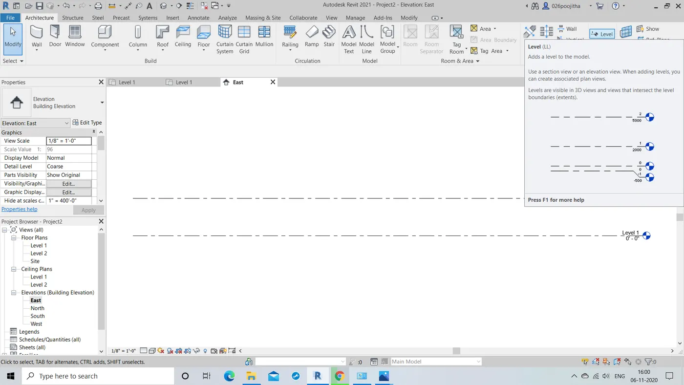
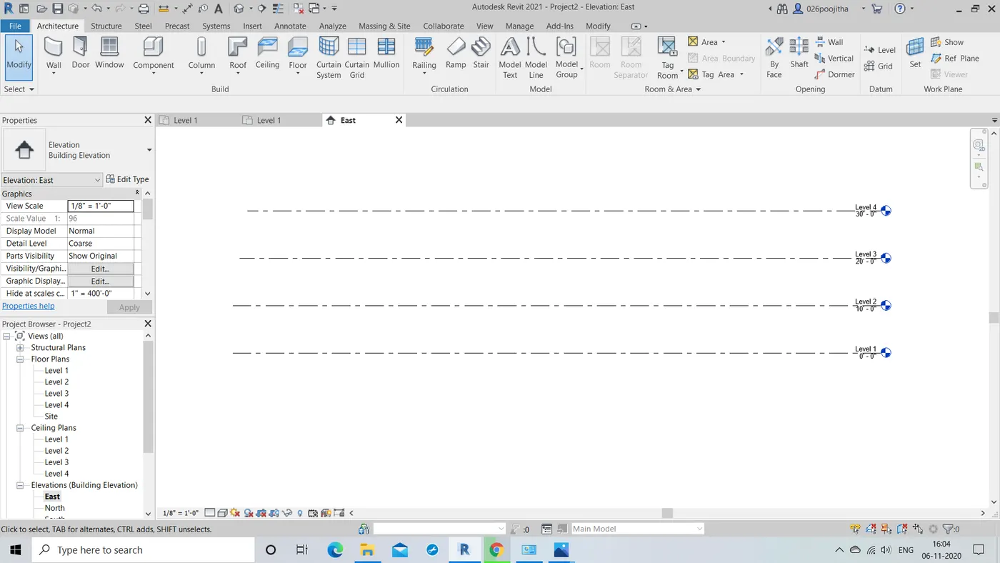
- Firstly click on the architectural template and click on east under the elevations.
- The elevation of the desired view is seen on the screen ,rename it and place them at the required distances.
- If required we can add new level for the roof by using the level option in the architecture tool bar
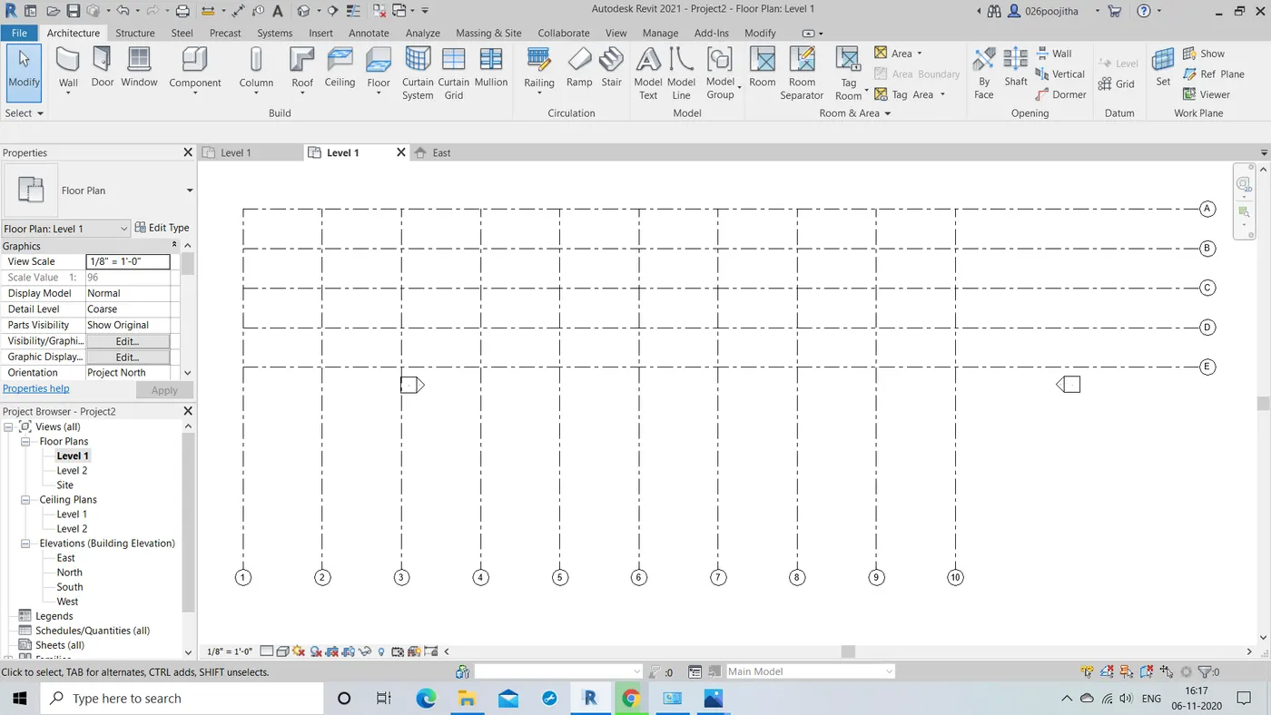
- Now select ground floor under the floor plans.
- Now select the grid option under the architecture tool bar, now place the grids an name them respectively such as for the horizontal(traverse)grids name them as A,B,C,D and E providing a equal spacing of 10'.
- In the same way name the other 10 vertical(longitudinal)grids starting from 1-10 with a equal spacing of 20'.
RESULT: levels representing ground floor, first floor, second floor and roof are seen at the heights of 0',10',20' and 30' respectively.The horizontal and vertical grids are seen with proper naming.
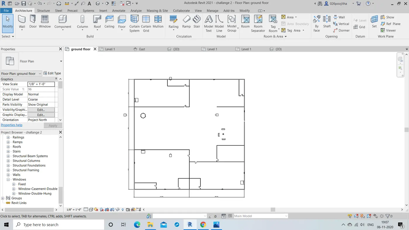
5.AIM: To create a consceptual layout of the residential unit that is 3D modelling of residential house.
TOOLS REQUIRED:
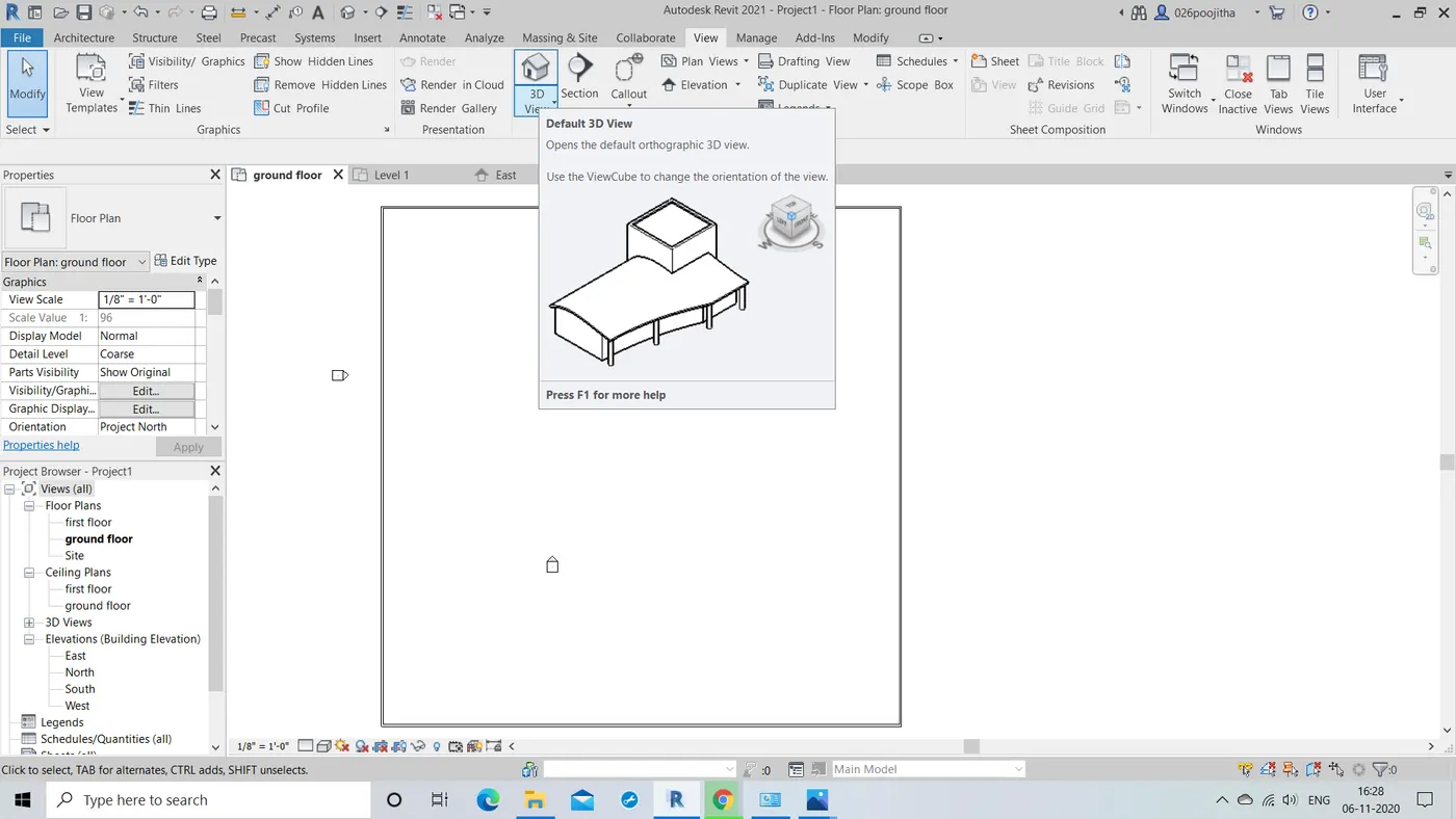
Architecture tool bar -> Wall icon, edit type tool,View icon -> Default 3D view icon.
PROCEDURE:
- Firstly select the architectural template and click ok.
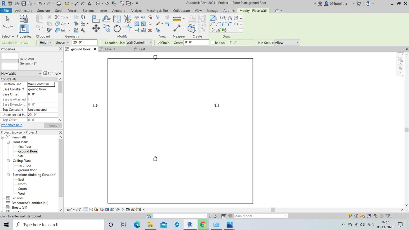
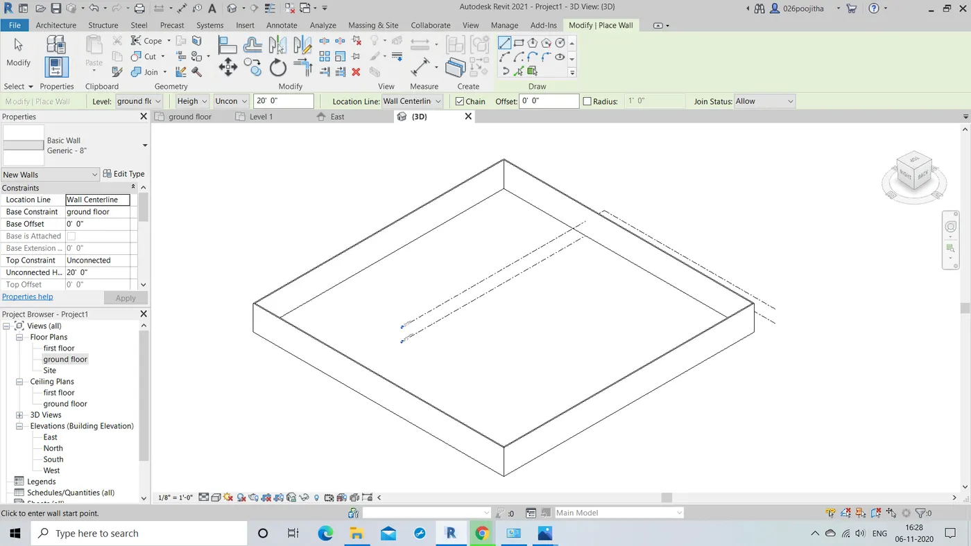
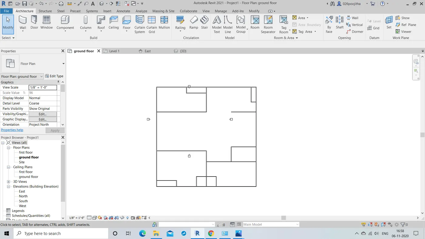
- Now by selecting the wall tool we will be able to draw the walls for the residential building with desired dimensions.
- After completion of the exterior walls change the wall size withe the help of edit type tool and draw the interior wall.
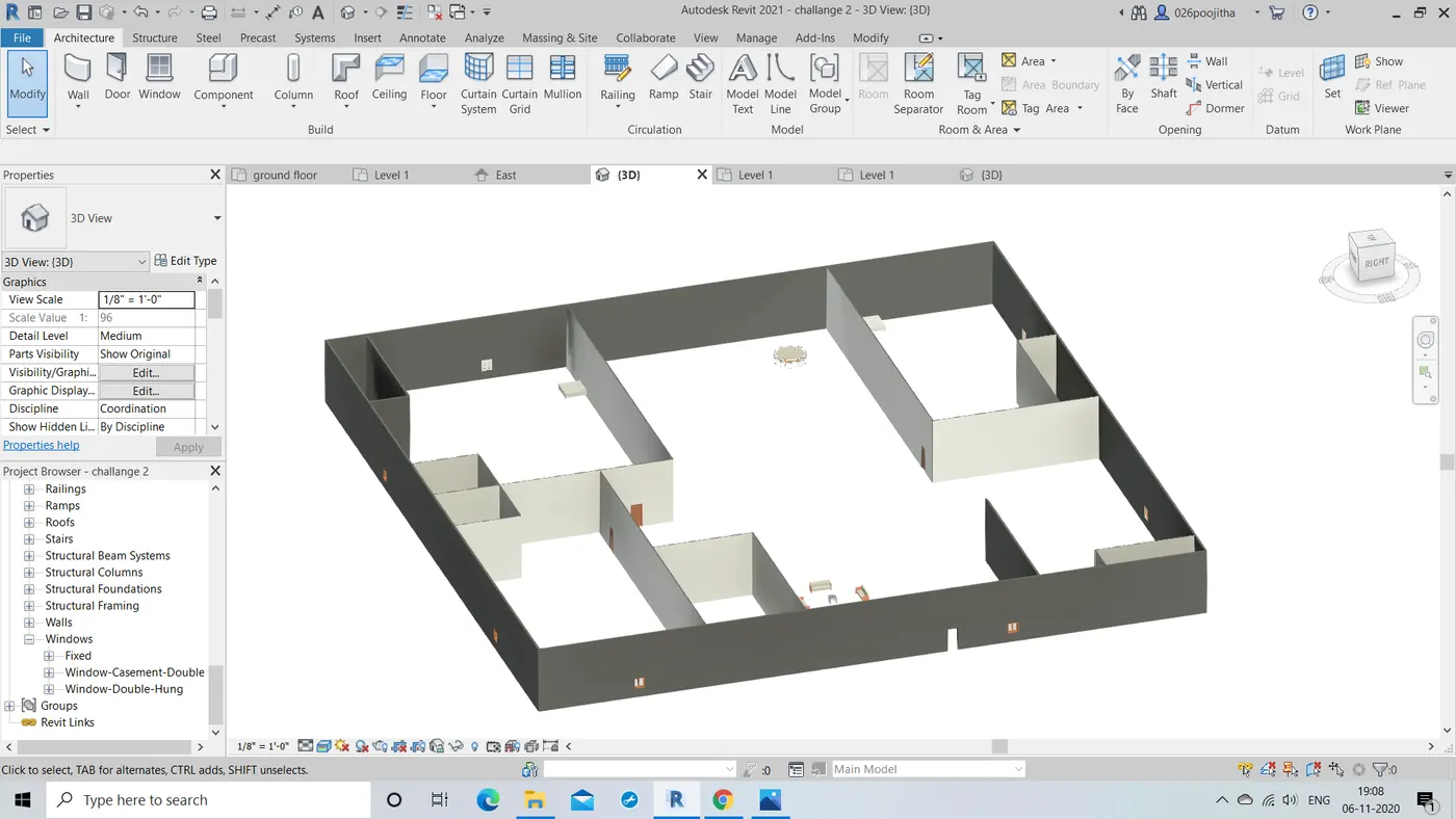
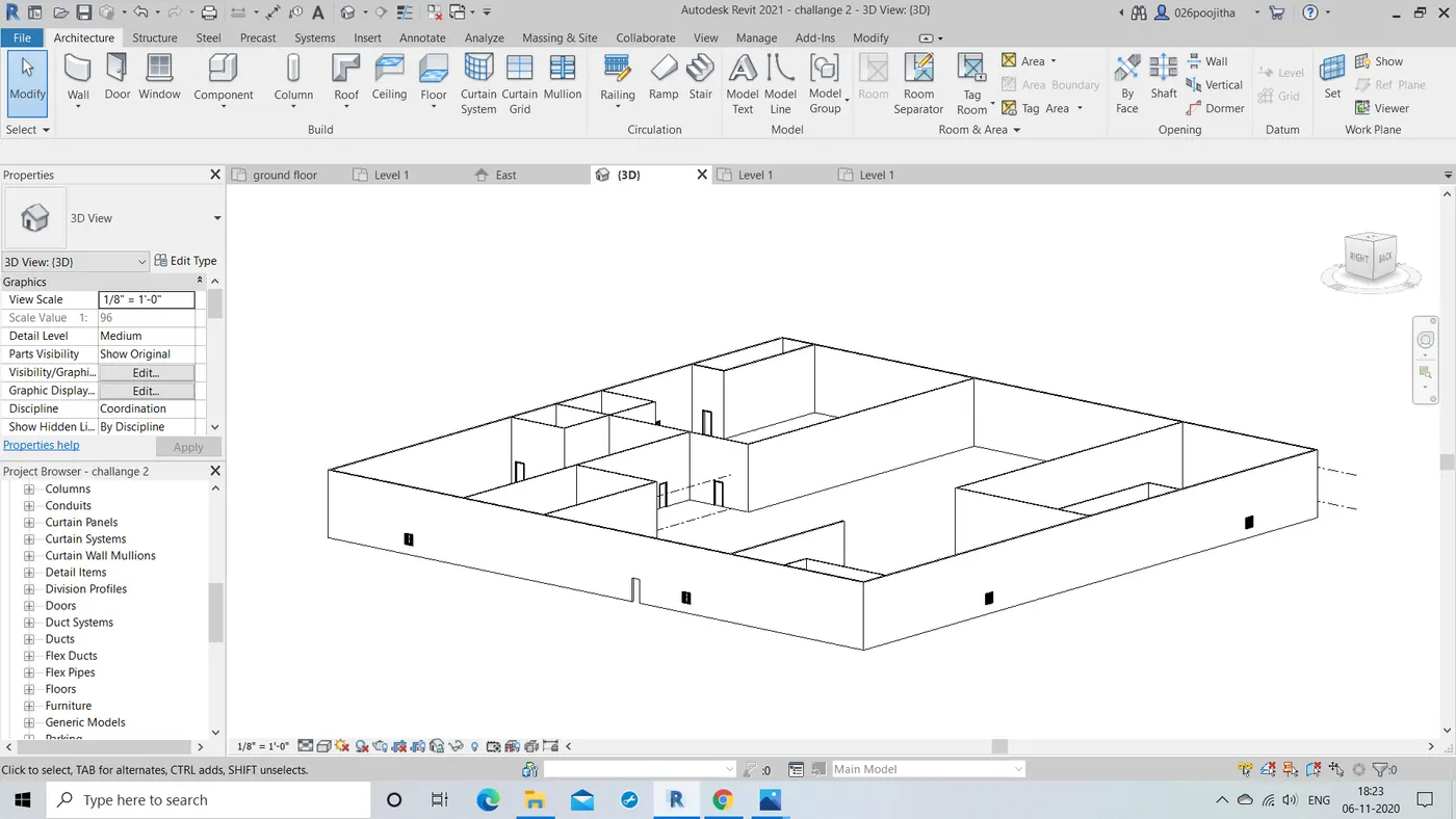
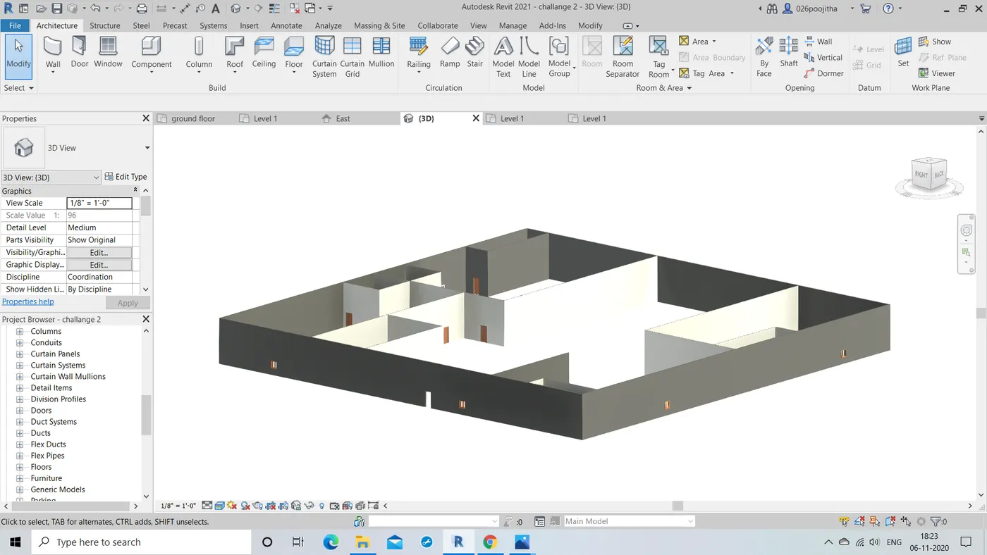
- Now click on the default 3D view option to convert to 2D project into 3D layout.
RESULT:
Hence the 3D view of the residential building is obtained and also the layout of it by following the above steps.
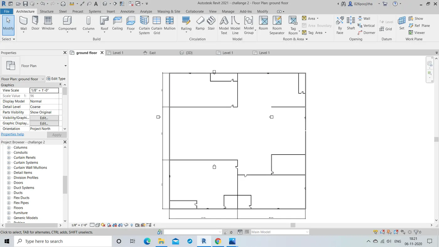
6.AIM:In the layout created draft the level of details you are planning to include the Dimension of room, add components to the residential unit.
TOOLS REQUIRED:
Insert icon -> load family, Architecture -> Window, door, view -> default 3D view.
PROCEDURE:
- Firstly after the completion of the layout for the residential plot.
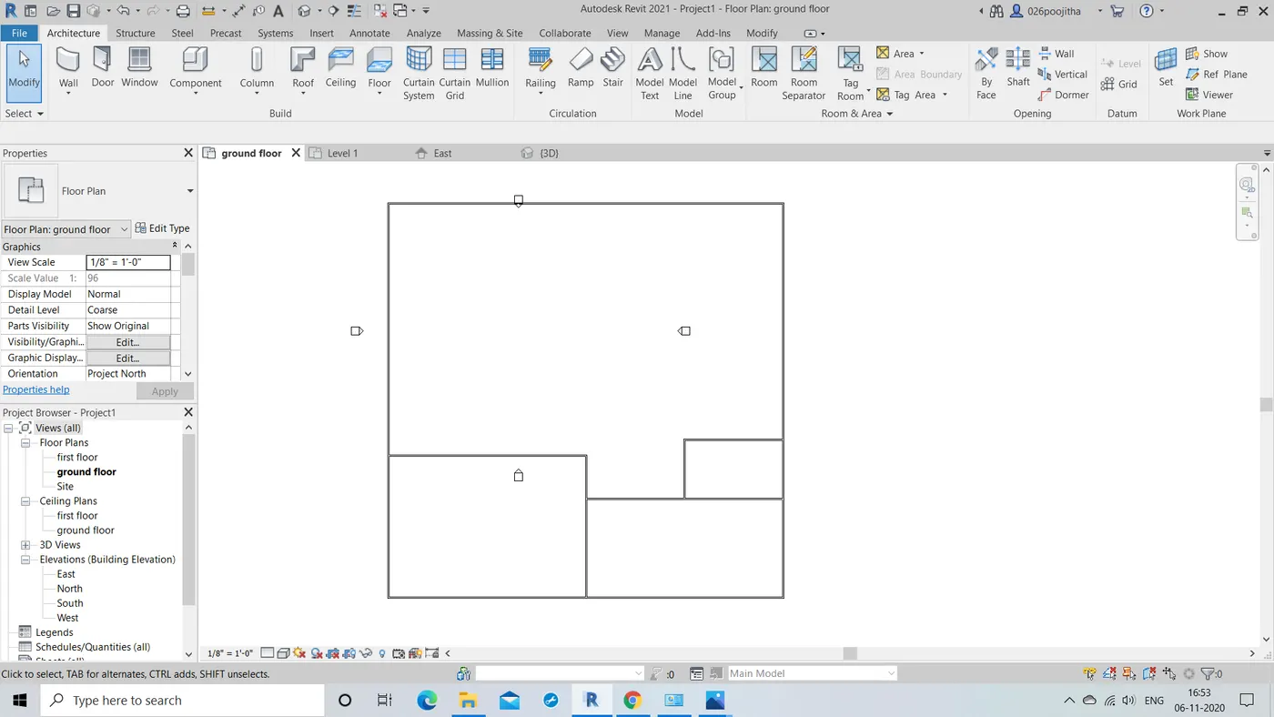
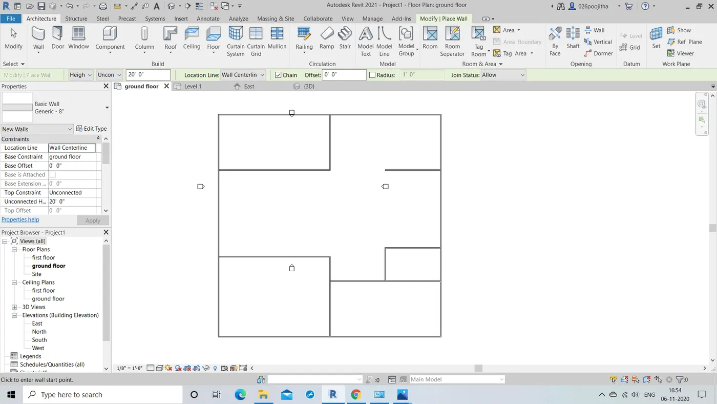
- Draw the remaining inner wall of the building using the wall tool present in the architecture tool bar.
- Now click the insert menu and select load family option to add the desired components.
- Now to mark the dimensions go to the annotate tool bar and select the aligned option.
- Select the view option then we are directed to a tool bar where we find a 3D view tool option to convert the project from 2D to 3D view.
- Make the 3D view realistic for a better view.
RESULT: Hence the 3D view of the residential plot is obtained also the dimensioning and the desired components are added.
7.AIM: To add the residential model elements such as Door, Windows, Tables, Chair, Couch, Bed, Lamps from the library and to insert them in the model.
TOOLS REQUIRED:
Insert -> load family, view, architecture -> doors, windows, components -> bed dinning table.
PROCEDURE:
- To start with the interior components, from the insert menu with the help of load family icon we can load the desired components such as beds, sofa and other furniture.
- With the help of the default 3D view option we convert the 2D view of the residential to a 3D view.
RESULT: By following the above procedure we can successfully get the desired interior options on to the project.