Week 5 Bending of iPhone
-
Objective: To perform simulation for bending of an iPhone model for given cases and compare the results.
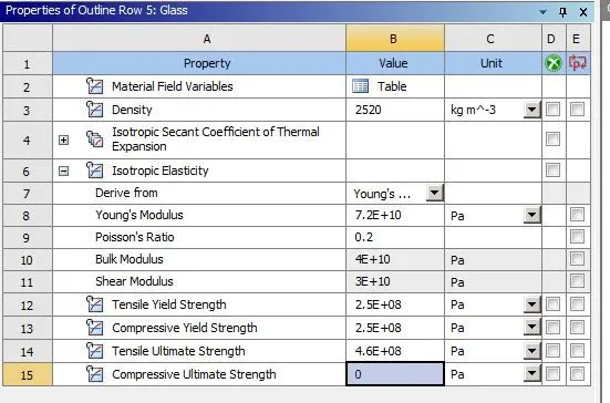
- Procedure: Open the static structural analysis system in the Project schematic. The material used for analysis are Polyethylene, glass and aluminum alloy. These materials are added to the material library in
Engineering Data. For glass, following material properties are defined:
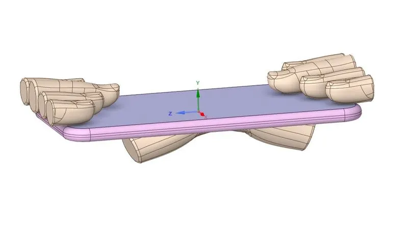
Now proceed to import the geometry. Import the Geometry. Open the Geometry in SpaceClaim. Ensure the geometry is properly imported by doing quick visual inspection. The geometry is properly
imported as observed.
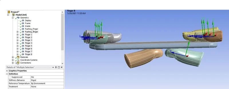
Update and open the mechanical module. Assign the material Glass to the phone display body, aluminum alloy for the frame and polyethylene material for the inside of the phone. For the shown
pushing finger and other fingers, set the stiffness behavior to rigid.
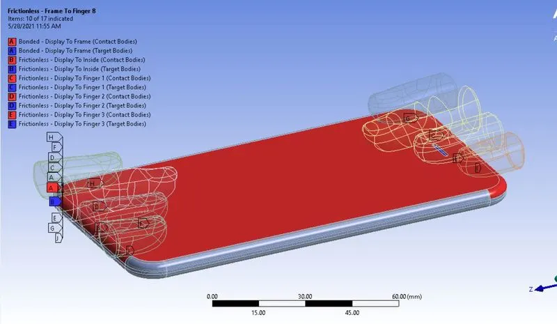
The Ansys automatic contact detection has detected contacts between the components of the phone and also between the fingers and the phone. The default detected contacts are accepted but the type of
contact is set to Frictionless for all the contacts except for the contact between Display and the frame. For contact between the Display and the frame, Bonded contact is defined which makes sense.
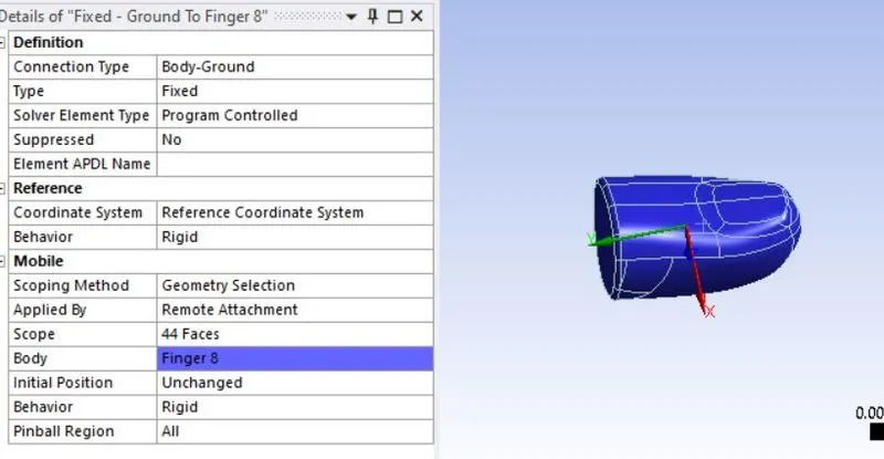
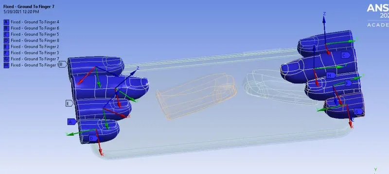
The fingers on the top should hold the phone in position, whereas the pushing fingers will push the phone upwards from down. Now insert Fixed joint for all the fingers. Go to Connections > Insert > Joint.
Select Connection type as Body Ground and type as Fixed. Select all faces of the finger as shown below.
Similarly, create Fixed joint for all the fingers as shown below:
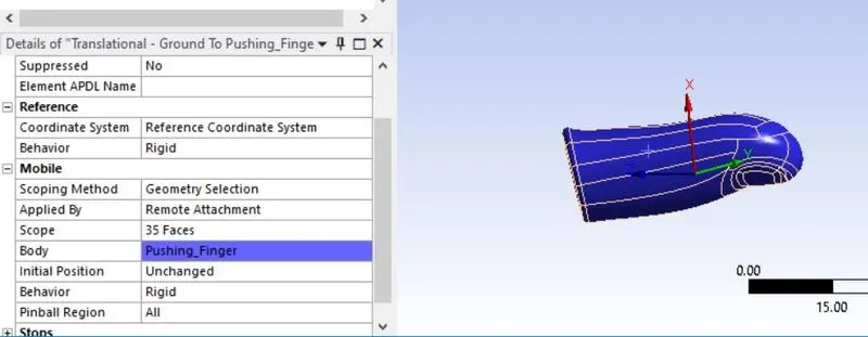
Insert Translation joint for the pushing fingers. Go to Connections > Insert > Joint. Select connection type as Body Ground and type as Translation. Select all the faces of the pushing finger as shown below:
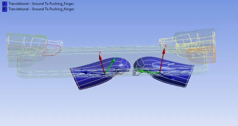
Similarly, Insert Translation joint for the other pushing finger.
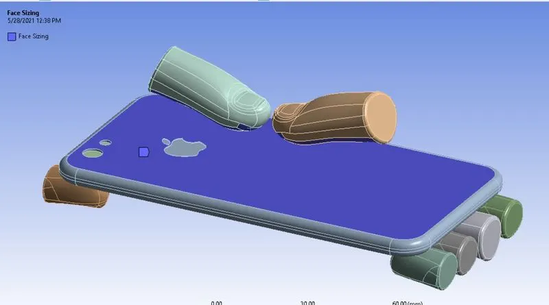
For meshing, mesh size of 4mm is used for the frame and the faces of pushing fingers as shown below:
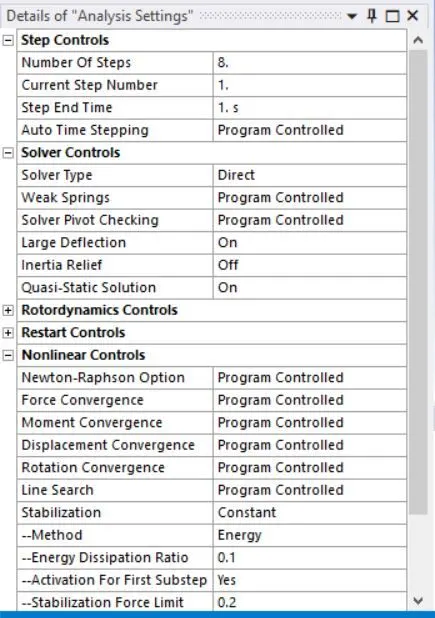
The displacement of the pushing fingers is divided into 8 steps. Therefore, 8 no. of steps is set in the analysis settings with the following parameters:
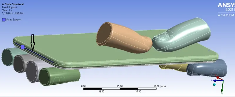
Now insert Fixed support for the sides of the body inside the frame so that it does not fly off when the load is applied.
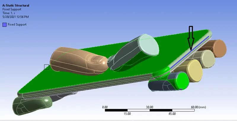
During the simulation, the phone should move only in the Y direction, so we have to constrain the X and the Z movement by using displacement joint on the displayed surface:
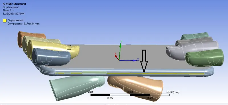
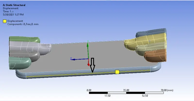
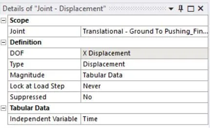
Insert joint load for the pushing finger. Go to Static Structural > Insert > Joint Load. Select the pushing finger joint with type as Displacement. Enter magnitude in tabular form for displacement as follows:
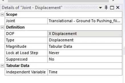
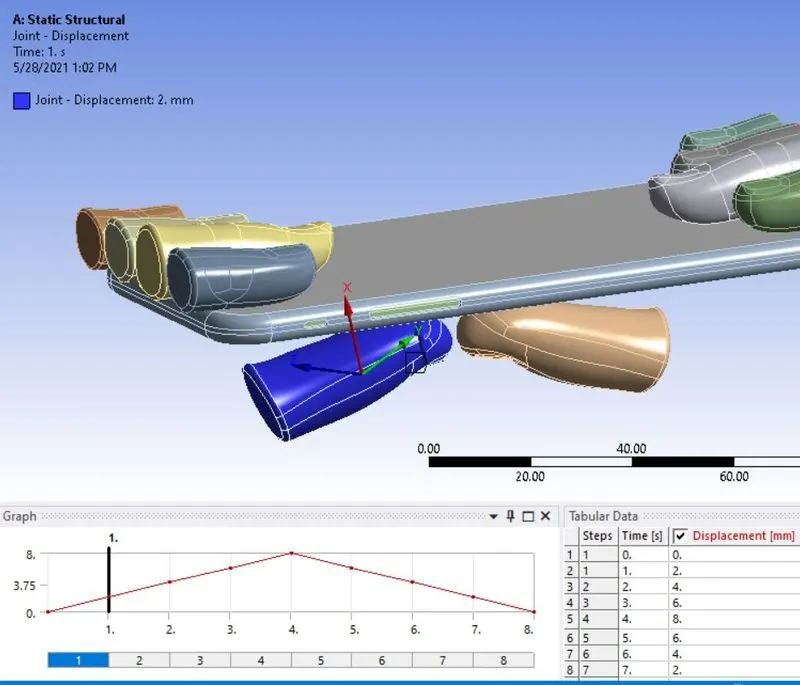
Similarly, define joint load for the other pushing finger.
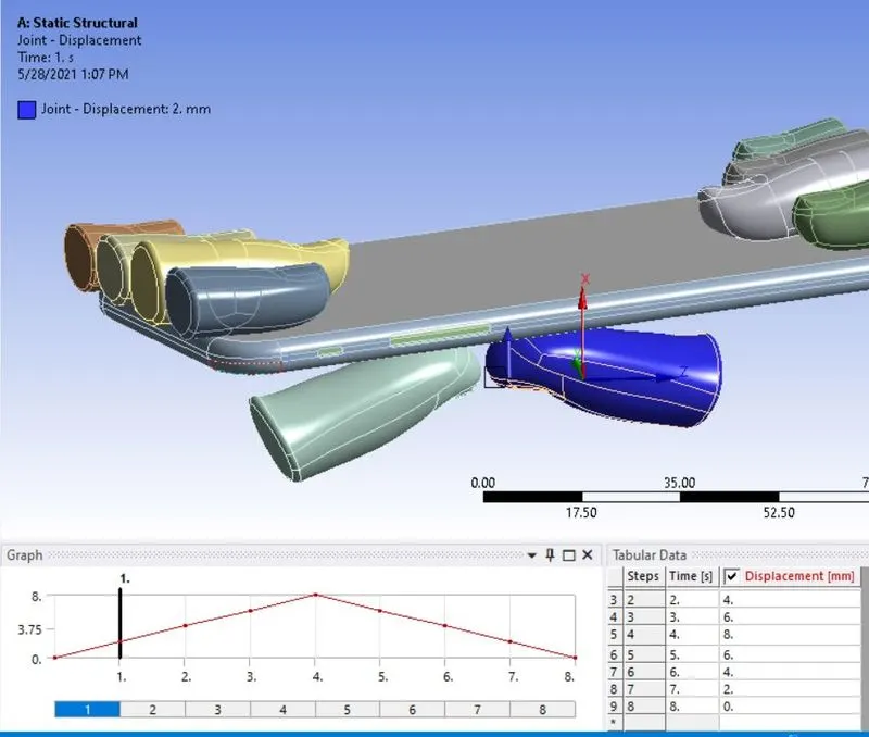
The case setup is now completed. List the required results and run the simulation.
- Stress Contour:
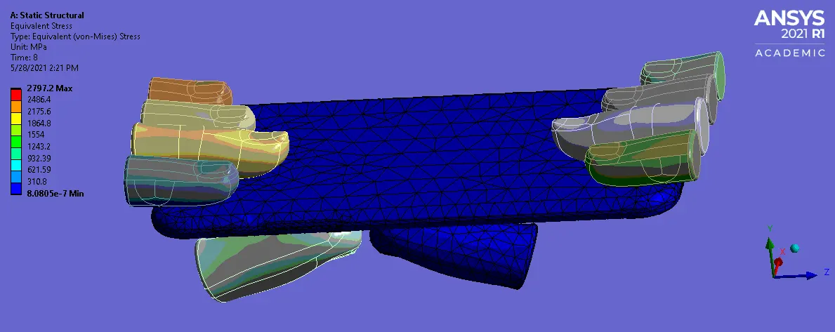
Max stress of 2797 Mpa is observed.
- Deformation: Y Direction
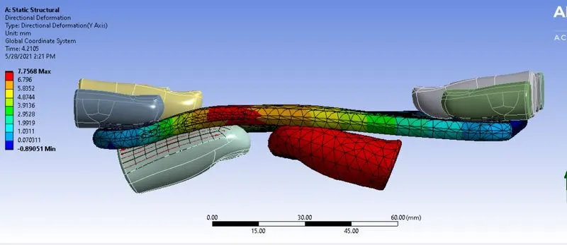
As seen above, deformation of 7.7 mm is observed in the model.
- Deformation of Frame:
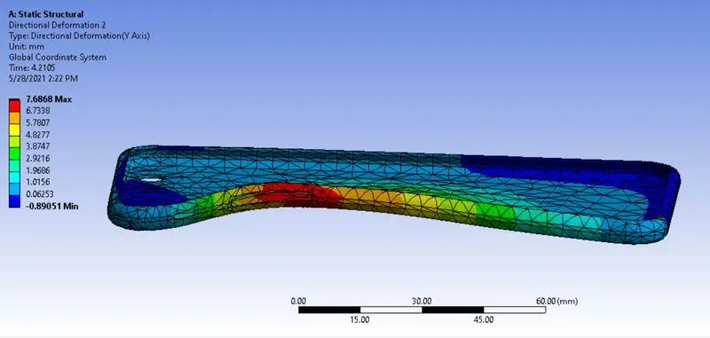
Deformation of 7.6 mm is observed in the aluminium case.
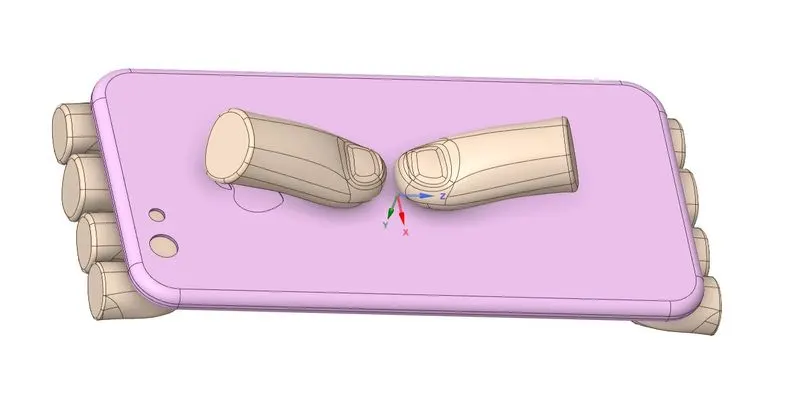
Case 2: The bottom pushing fingers are moved by X = 22.5 mm and Z = 10 mm. Using the new position of the fingers, which now at the centre of the phone, the simulation is repeated for the same loading
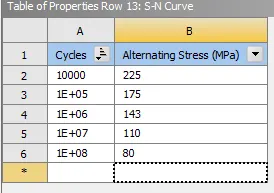
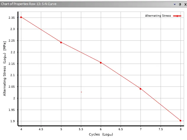
condition. Also, S-N curve for the aluminium frame / case is defined and the Factor of safety and life is evaluated. The new position of fingers and the S-N curve defined is shown below:
- Stress contour:
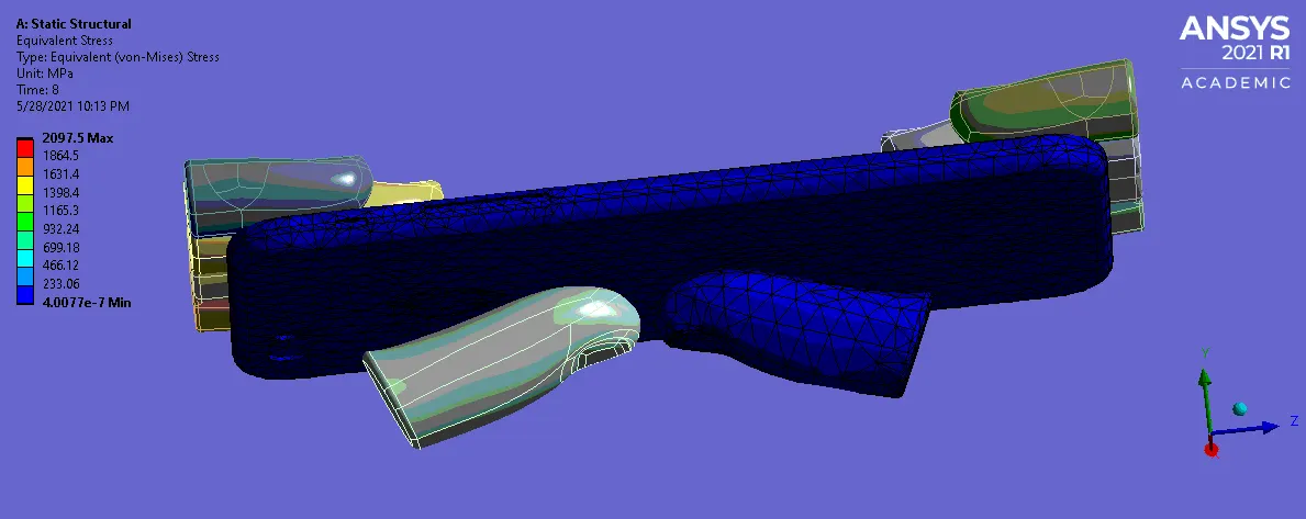
Max stress of 2097 Mpa is observed.
- Deformation in Y direction:
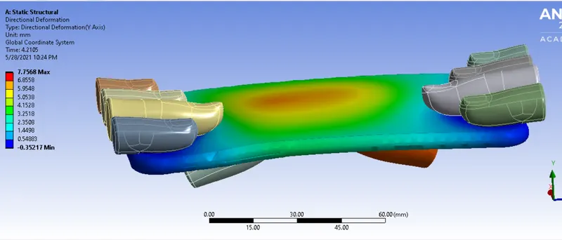
Max deformation of 7.7 mm is observed.
- Deformation of aluminium Frame:
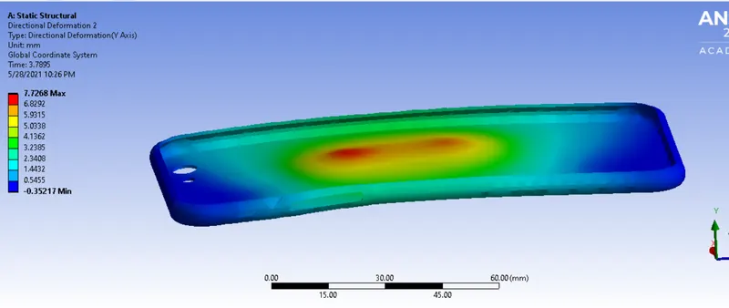
Max deformation of 7.7 mm is observed in the frame made of aluminium.
- Factor of safety:
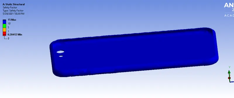
Max factor of safety observed is 15, however min observed safety factor is less than 1.
- Life of alumimium case:
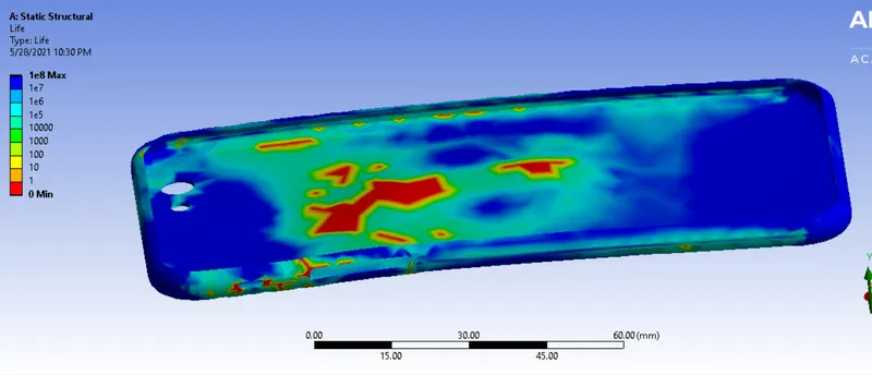
Max life cycle of 1e8 is observed.
- Comparison of Case 1 and Case 2:
In both the cases, same value of deformation is observed. However, the stress concentration observed is more in case 1 where the loading is applied at the near edge of the aluminium frame. In
comparison, the stress distribution is more uniform in case 2 where the loading is applied at the centre of the frame and hence, comparatively less stress is observed compared to case 1.
- Conclusion : Thus the bending simulation of an iPhone model was successfully completed and the deformation and life cycle along with factor of safety was evaluated.