Project 2
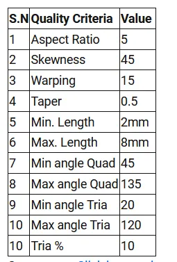
- Objective: Mesh the given component using given criteria and assign thickness.
Target Element Length = 5mm
- CAD Model:
- Procedure:
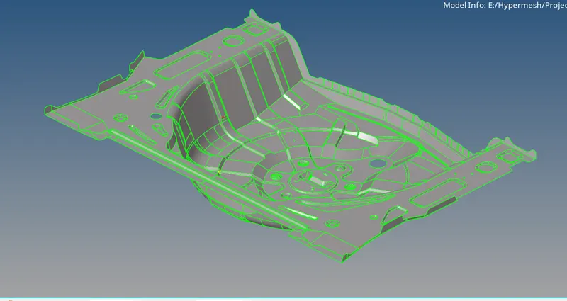
Open the given .hm file and set the Gemoetry color mode to By Topo. It is seen that the given component is a sheet metal component. The thickness of the component is calculated by measuring the
distance between node from a particular surface to the node projected on the opposite side of the surface. The thickness of the component is 0.75 mm. Upon checking for any geometry error, few
free edges are found. We will fix them after we have extracted the mid surface.
We will extract the midsurface manually by offsetting the surface from the outward side. Create a new component and rename it to Midsurface. Go to Geom page > surface edit > offset. Set the method
to contionous offset. Select all the surfaces from the outward side.
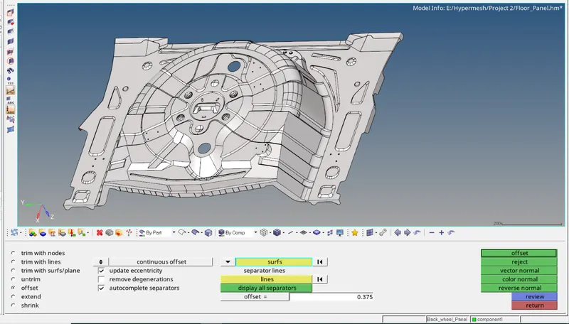
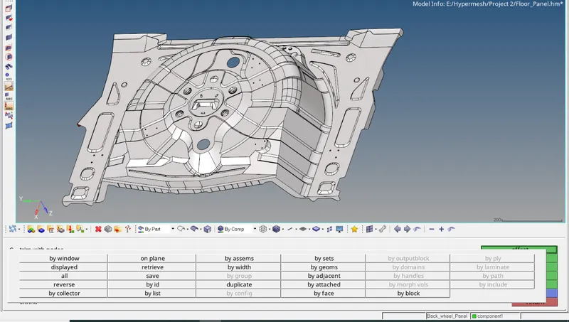
Right click on the entity selector box and click on duplicate > to curent component. Click on color normal. If the direction of normal is okay, we can offset the surface.Click on reverse normal if the noormal
direction is in opposite direction. Enter the offset distance = 0.375 and click on offset. The duplicated surface will be offset.
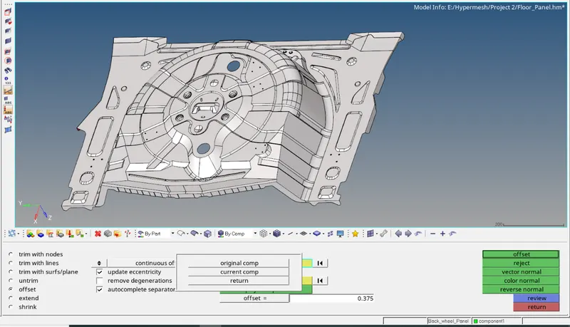
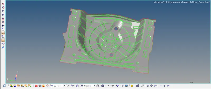
The midsurface is now extracted. Now let us fix the free edges in the midsurface component. These are easily fixed by using toggle option from the Quick Edit panel.
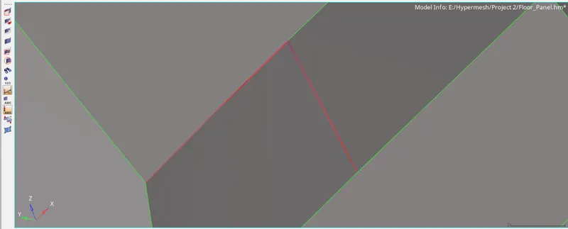
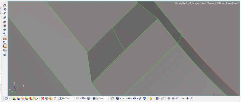
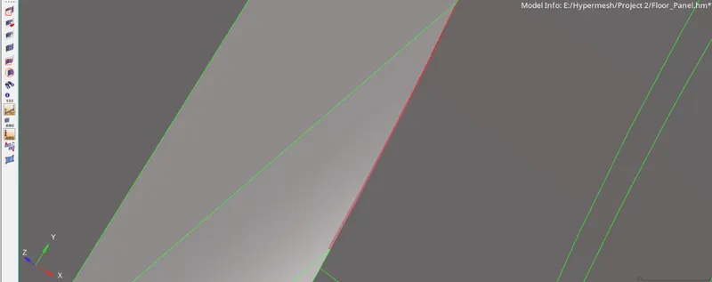
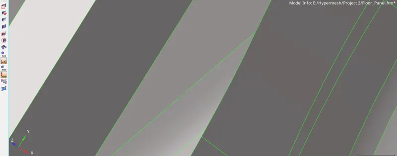
There are also small embossed features on the components, which are very small in size. These cannot be meshed using the given element crtieria, so let us remove them. .
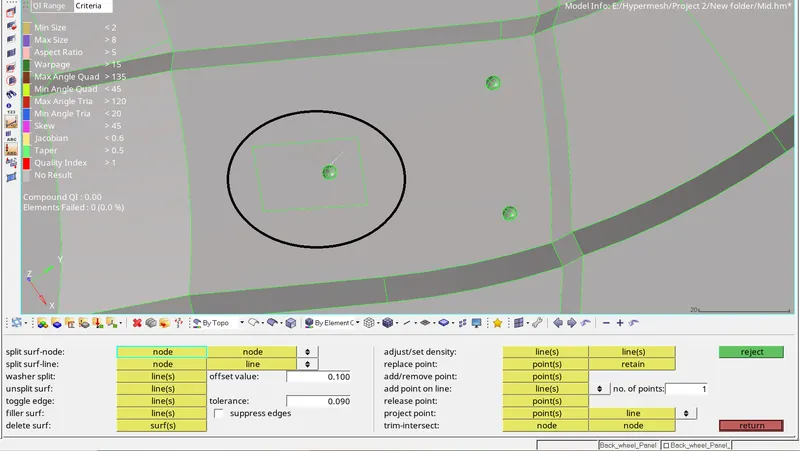
Using split surf-node option from the quick edit panel, trim a small surface containing the embossed feature as shown above. Now delete the trimmed surface.
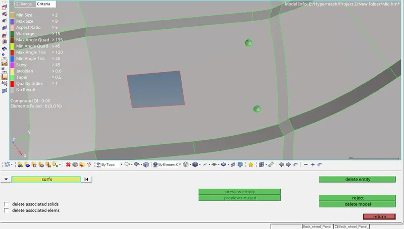
Go to Geom page > surfaces > ruled to create a new plane surface here.
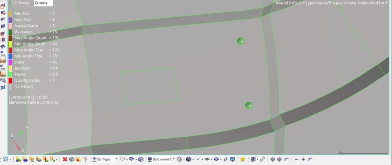
Repeat similar procedure for the remaining embossed features to remove them. Now toggle all the unnecessary split lines so we can maintain proper mesh flow and maintain the element quality.
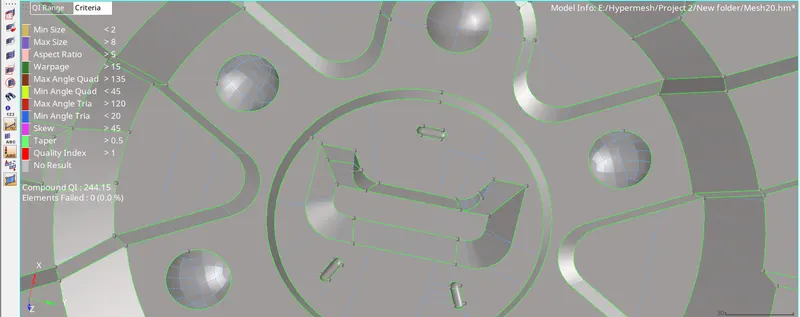
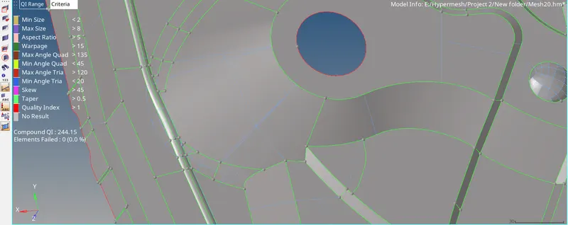
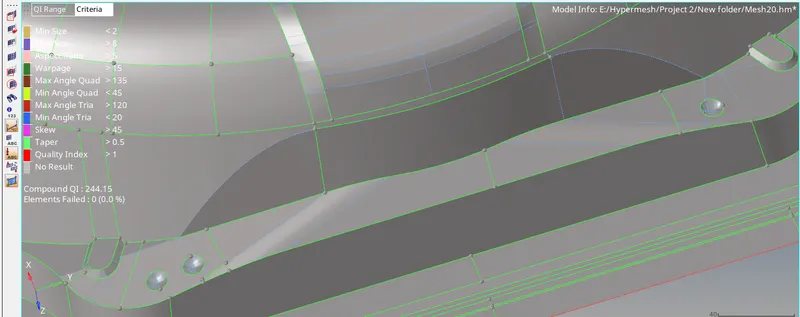
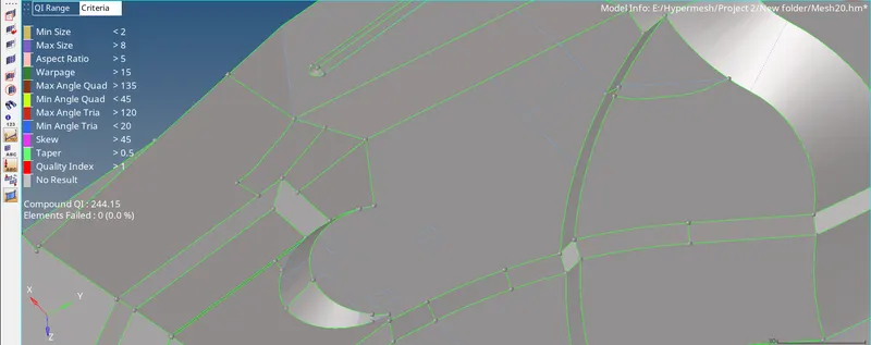
Now the component is ready to be meshed. Go to automesh panel. Enter element size = 5. Keep the mesh type as mixed and mesh the component. The meshing is started from the centre and carried
out in the outer direction towards free edge.
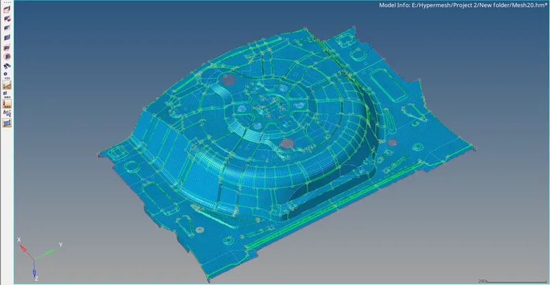
After meshing is completed, check for the elements failing the given quality criteria. Majority of the elements are failing for warpage, which is the out of plane angle. These are fixed by using the translate
tool under the Tool page.
Go to Tools > translate. Before fixing the failed element, check the warpage of the adjacent elements. The purpose of this is to identify adjacent element with minimum warpage, so that we can we can move
the nodes of fialed elements and transfer the warpage of failed element to the adjacent elements with low warpage.
Select the node to be translated. Select the nodes N1, N2, N3 to define the plane for translation and then translate the node to fix the element.
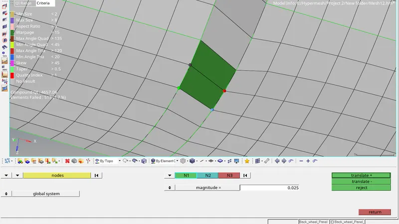
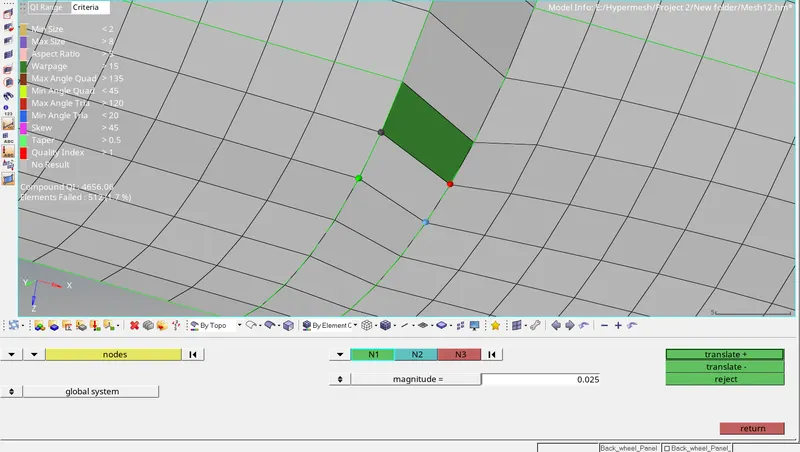
For the elements failing for min and max length, aspect ratio criteria, these can be easily fixed by adjusting the distance between nodes by usning the distance panel. By bringing the elements close to
its ideal shape by adjusting distance between nodes can fix elements failing for skewness and taper , min and max angle for quad and trias.
After fixing the failed elements, we can now check for any free edges in the model. There should not be any free edges in the model otherwise the load will not be transfered further from the free node
and we will get wrong results after simulation. To check for free edges, go to Tools > edges. Select the entity selector to elements. Select all the elements and click on find edges. Isolate the free edges
and press F fit to scrren.
Technically, there should be free edges only at the outer boundary and holes. Any free edges except these places indicates that the nodes there are not connected to the adjacent nodes of the elements.
As shown below, many free edges are found.
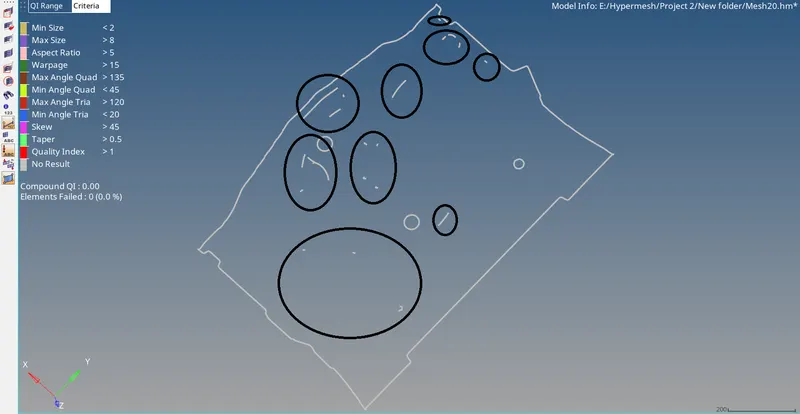
We can easily fix them by using equivalence option. Go to Tools > edges > elements. Select all the elements. enter tolerance value = 0.01 and click on equivalce. Now delete the free edges and once again
extract free edges so see if there are any free nodes which are out of the search tolerance which we entered. This time no free edges are found.
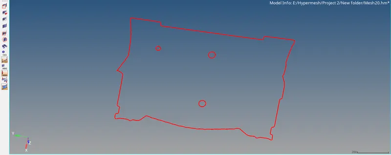
Last important check left to do is now checking the direction of the normals. To check the direction of normals, go to Tool > normals. Select all the elements and click on display.
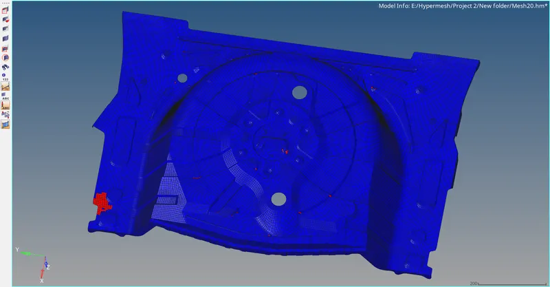
Click on adjust to adjust the direction of the normal which are not proper as seen above.
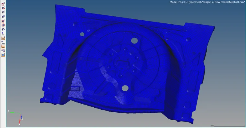
The complete pre-processing of the component is now completed.
.