Week 4- Challenge
- Objective:To create 1D elements with the given cross-section and DOF's on the give component.
a. Rod element:- with only translational DOF and RBE2 link
Cross-Section: BOX- Dimension a= 12 mm
dimension b=10 mm
Thickness t= 0.75 mm
b. Beam element:- with all DOF and RBE3 link
Cross-Section: I Section- Dimension a= 8 mm
Dimension b= 10 mm
Dimension c= 8.5 mm
Thickness t1= 0.75 mm
Thickness t2= .6 mm
Thickness t3= .6 mm
c. Bar element:- with only x and y DOFs With RBE3 link
Cross-section: CROSS section- Dimension DIM1= 5 mm
Thickness DIM2= 1.2 mm
Dimension DIM3= 10 mm
Thickness DIM4= 1.2mm
d. & e. apply the mass of magnitude 10 with RBE2 link
f. Join the two components with Spring elements
- Prodecure:
Import the CAD model. Go to File > Import > Geometry.
Select File type as as IGES. Click on the Select Files icon. Navigate to the folder where file is stored, and select it. Click on open. Then click on Import.
Now extract mid-surface of given geometry.
Go to Geometry > midsurface. In order to properly capture edge fillet, click on extraction options and select skin offset.
Now click on auto extraction, select the surface and click on extract. The midsurface will be extracted.
Similarly extract the midsurface of another side and move them into seperate components. Do washer split on the two surfaces near the holes and mesh them.
To create RBE2 link, go to 1D > rigids
Select the nodes as displayed. Select elements type as RBE2 and click on create. RBE2 links will be created. We will update DOF later. Repeat the procedure at required places of the two components.
Similarly to create RBE3 link, go to 1D > rbe3.
Repeat the above procedure. Select the required nodes and create the RBE3 link at required places of the two components.
To define the cross-section of the 1D elements we will create, go to 1D > Hyperbeam > Standard section > standard section type > thin walled box > create.
Enter the dimensions value for a, b and c. To create I cross section, right click on Hyperbeam view > Create > standard section > optistruct > I. Enter the dimensions.
Similarly create the cross-section.
To create material properties, right click on the model view window, create > material. Rename it to steel. It will have default values of steel. Set card image as MAT1.
To create propertiesfor the 1D elements, right click on the model view window > create > property.
Let's create properties for rod element. Rename the created property to Prod.
Edit the Card Image as PROD, material as steel and Beam section as box_section1.
Similarly create properties of bar and beam elements with respective cross-section, card image and beam section.
Also create properties for 2D elements of midsurface with card image PSHELL and T=5 units and material as steel. And update the midsurface components having mesh with this property.
To create the 1D bar element, go to 1D > rods.
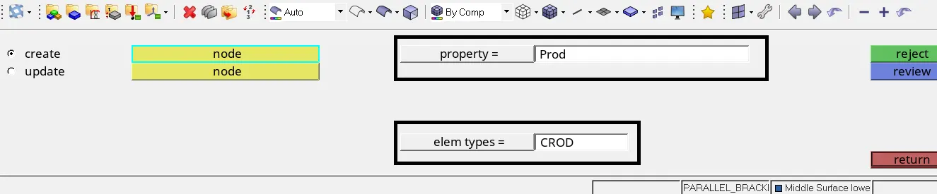
In property, select Prod. Element type as CROD.
Select the nodes displayed. Element will be created.
To create beam element, go to 1D > bars > bar2. Select property > Pbar and element type > cbeam.
Select the nodes displayed. Elements will be created.
To create bar element, go to 1D > bars > bar2.
Select property > Pbar and elem types > Crod.
Select the displayed nodes. Element wil be created.
To apply mass on thr RBE2, go to 1D > masses. Select the displayed nodes. Enter the value of mass = 10.
Select element type as CMASS1. Mass will be applied at these nodes. Repeat the pocedure for another side.
To connect the two components by spring, go to 1D > springs. Select the nodes displayed. Element types as HMSPRING. Repeat the procedure for another side.
Now update the DOF of the 1D elements.
For Rod element, go to rigids > update > dof.
Select the extreme nodes and check all dof expect dof2.
Similarly for beam and bar, go to 1D > rbe3 > update. Select the extreme nodes and uncheck all dof for beam and dof1, dof 2, dof4 and dof5.
- Final FE model