Week 9-Challenge
- Objective:
Create connector and Attach the various parts of the given model
1. Right_Rail_2 & Front_truss_1:- Seam-Quad(angled+capped+L)
2. Left_Rail_2 & Front_truss_1:- Quad elements
3. Front_truss_2, Front_truss_1 & Right_Rail_1:- Spot weld with 3 Layers and 5 mm Diameter
4. Front_truss_2, Front_truss_1 & Left_Rail_1:- Hexa (Adhesive)
5. Rear_truss_2 & Right_Rail_2:- Bolt Connector
6. Rear_truss_2 & Left_Rail_2:- Bolt Connector
7. Right_Rail_1 & Right_Rail_2:- Spot-weld with Rigid Elements
8. Left_Rail_1 & Left_Rail_2:- Spot-weld with Spring Elements
9. Rest all the component left Join them with suitable connectors
- CAD Model:
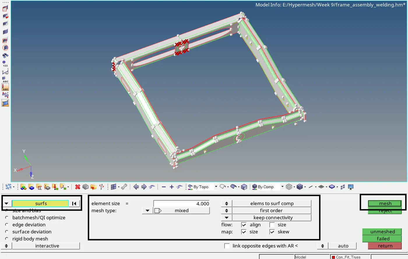
- Procedure: Import the Hypermesh model with .hm extension. Given component is a surface component as visualized when Geometry color mode is switch to By Topo. Now we concerned with only with creating connectors and connecting the components, we will directly mesh the given component with 2D elements with element size of 4mm. Go to automesh panel. Press F12 and set entity selector to surface. Enter element size as 4mm and set elements to surface component. Keep mesh type as mixed and click on align and click on mesh.
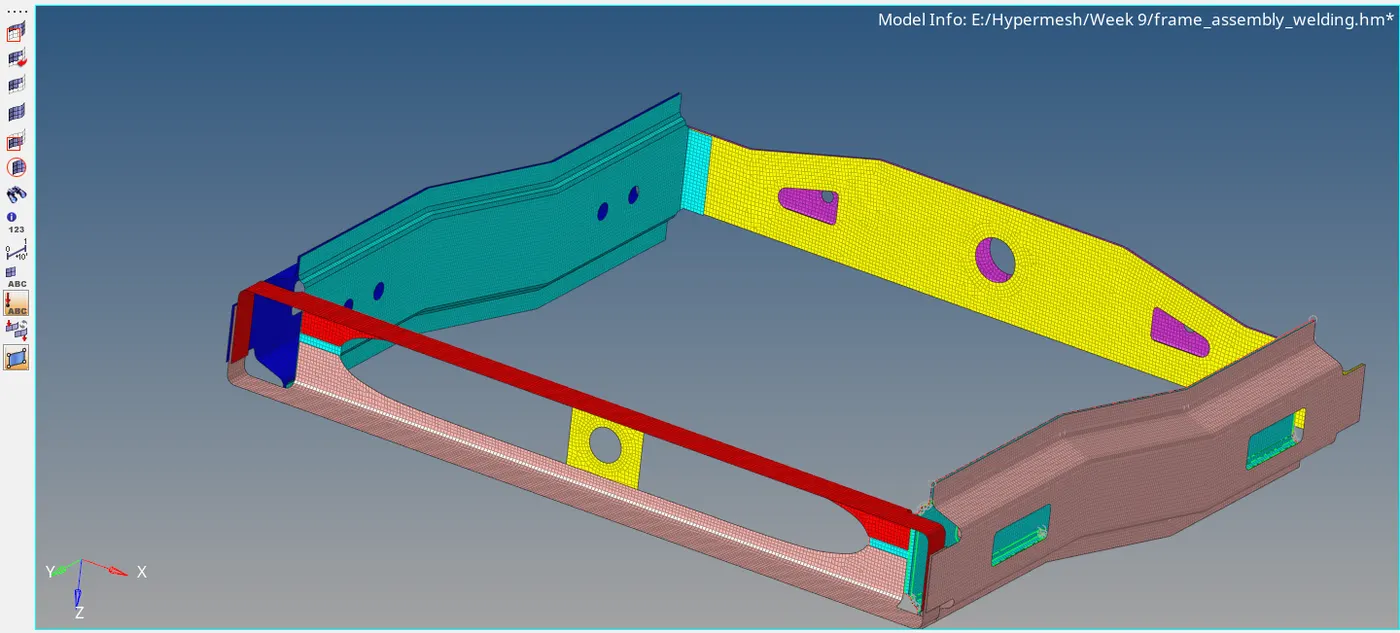
The component will now be meshed now as shown below. Accept the default generated mesh flow.
Now we can directly move to next step, i.e connecting the components using connectors. We will now connect the Right_Rail_2 & Front_truss_1 using Seam-Quad(angled+capped+L) connector. This
connector can be found under 1D/2D page > connectors > seam. Now turn off display for everything, except the Finite Elements for Right_Rail_2 & Front_truss. Go to 1D/2D page > connectors > seam.
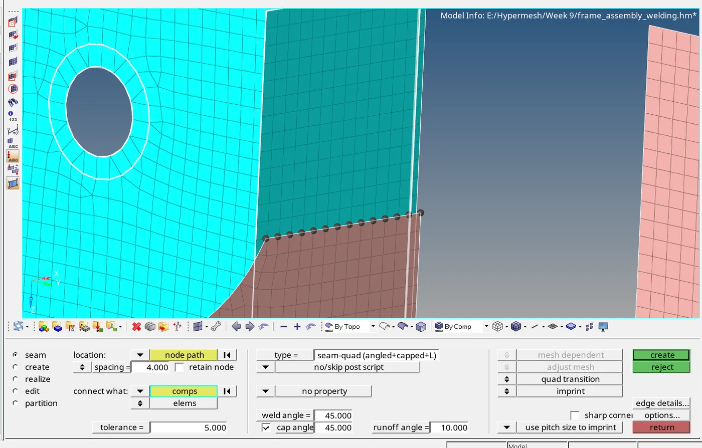
Under seam tab, unde location entity seletor, select the displayed nodes. Enter spacing, which is the target size of connector element as 4mm and enter search tolerance as 5. 4 mm spacing is selected
because the gap between all individual components is approximately 3.9 mm. Under connect what selector, select the Right_Rail_2 & Front_truss_1 components. Select type as Seam-Quad (angled +
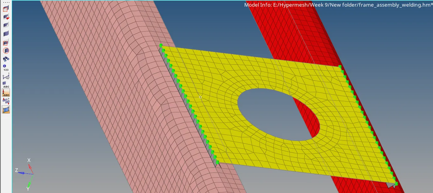
capped +L). Enter weld angle as 45 degree. Select quad transition and keep imprint option on. Click on create. The connector will be created.
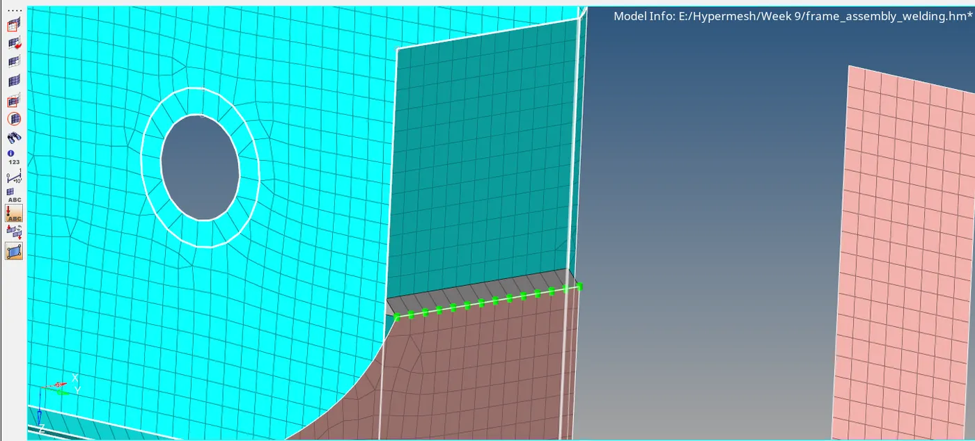
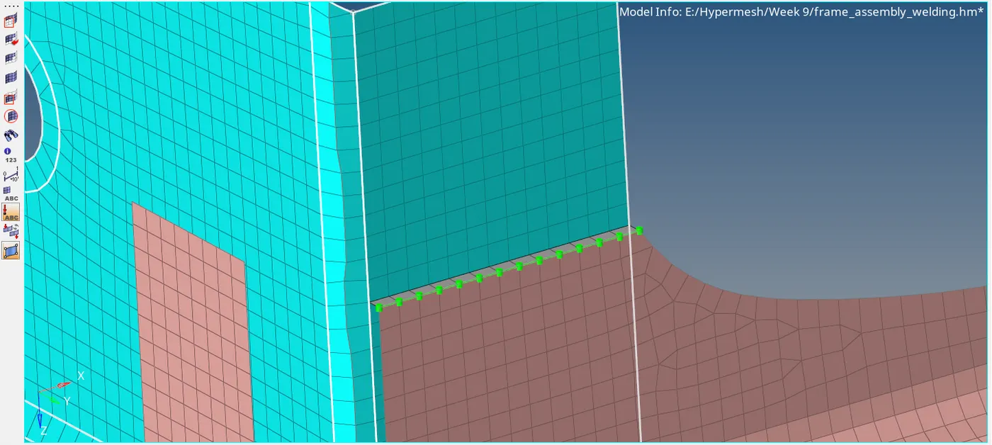
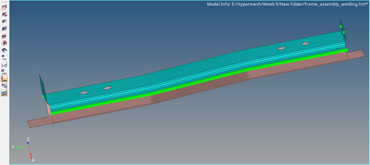
The connectors are now created. Green color indicates that the connecters are realized.
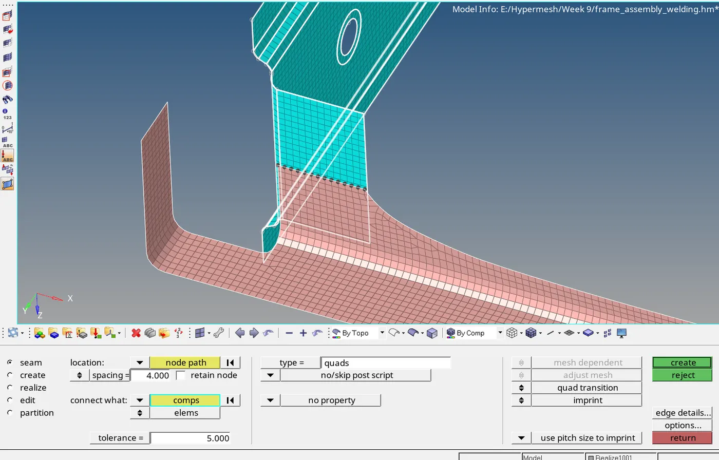
Now we will connect Left_Rail_2 & Front_truss_1 using quads. This is also found under 1D > connectors > seam. Now turn off display for except Left_Rail_2 & Front_truss_1. Go to 1D > connectors >
seam. Under location selector, select the displayed nodes. Enter spacing as 4 and search toloerance as 5. Under connect what selector, select the Left_Rail_2 & Front_truss_1 components. Select type
as quads. Select quad transition and keep imprint option. Create create. The connectors will be now created. As seen, the connectors are realized.
Now connect the Left_Rail_1 & Left_Rail_2 using Spot-weld with Spring Elements. Go to 1D > connectors > spot. Select the diplayed notes under location selector. Under connect what select Left_Rail_1
& Left_Rail_2 components. Select no of layers as 2 and search tolerance as 5. Select types as spring and click on create.
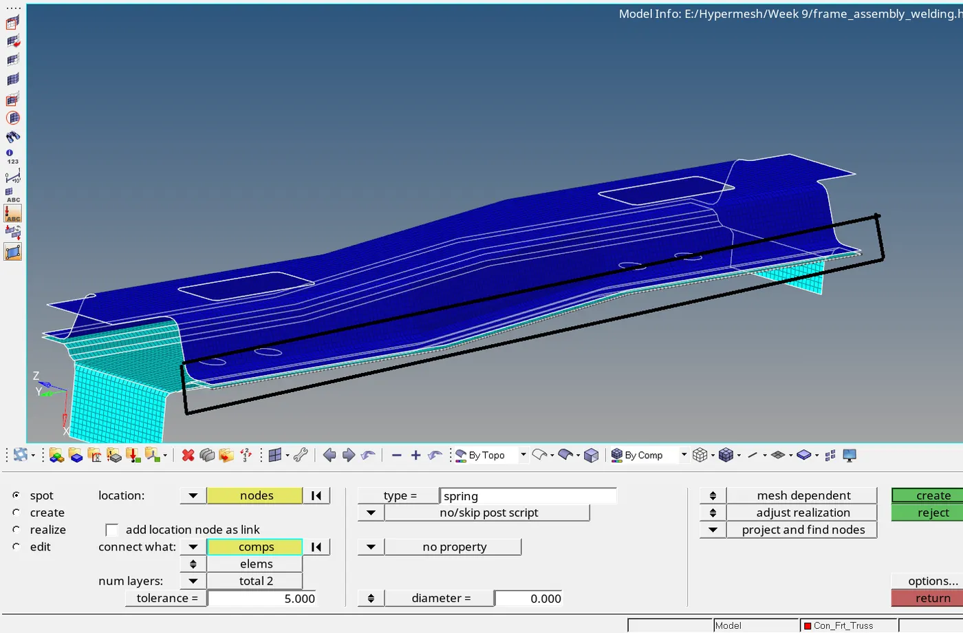
The connectors are created and realized. Repeat similar procedure for left side.
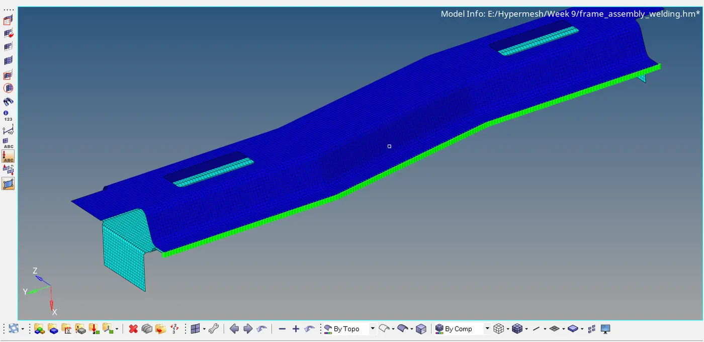
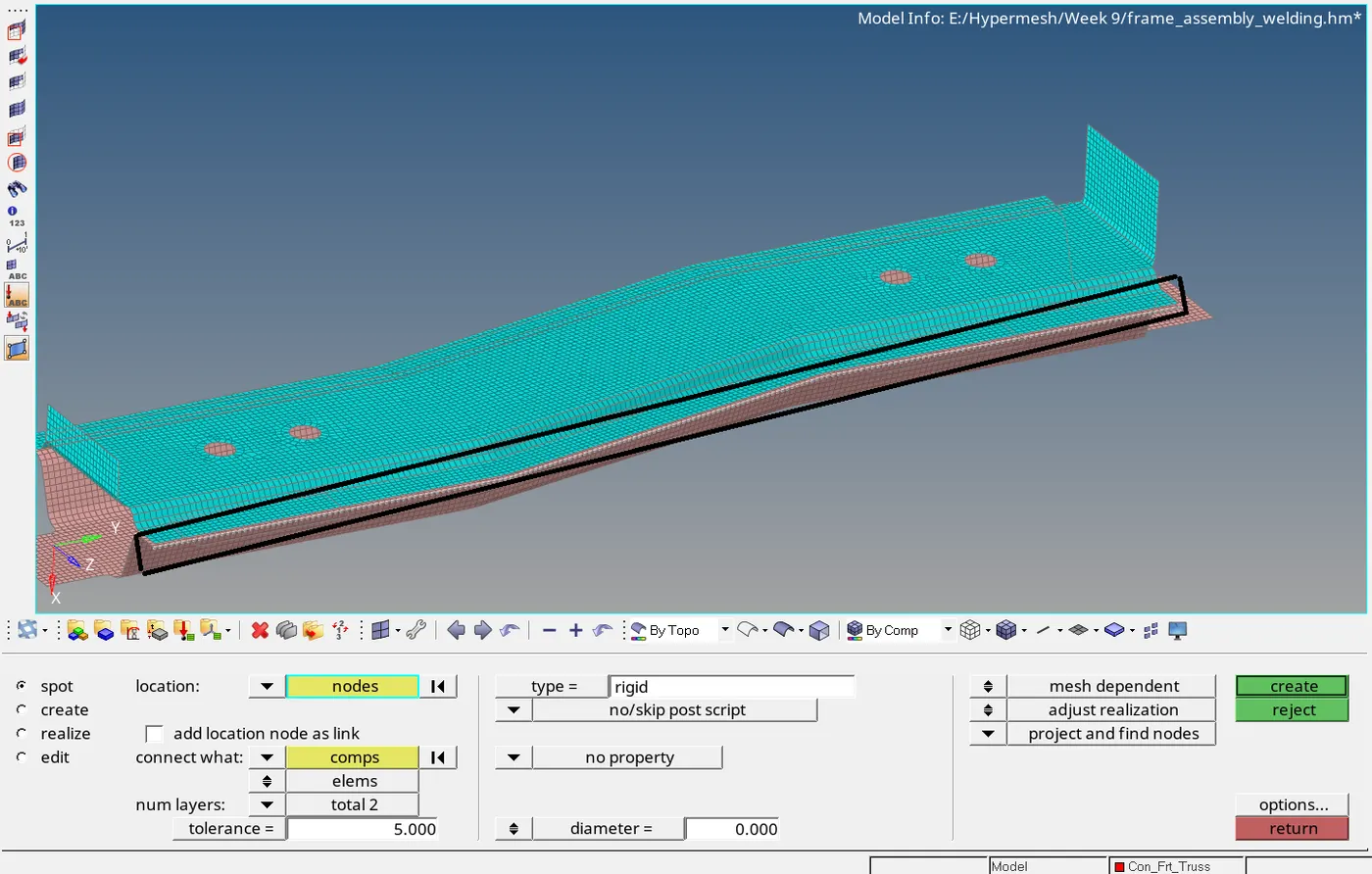
Now connect Right_Rail_1 & Right_Rail_2 using spot connected with rigid type. Go to 1D > connectors > spot. Select the displayed notes. Under connect what components, select Right_Rail_1
& Right_Rail_2. Set no of layers = 2 and search tolerance as 5 and with type as rigid. Click on create.
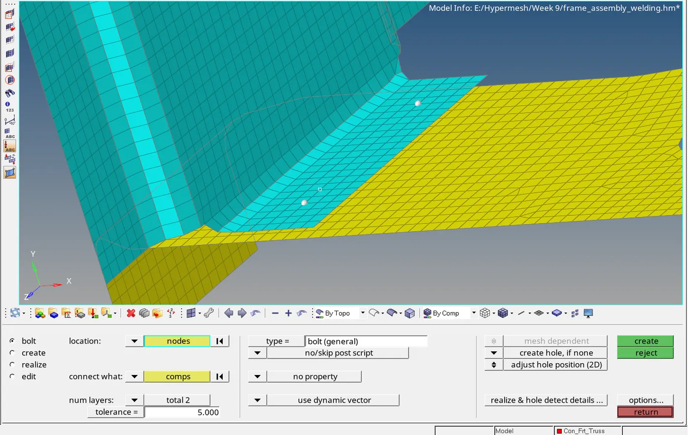
To connect Rear_truss_2 & Left_Rail_2 using Bolt Connector, go to 1D > connector > Bolt. Under location, select the displayed nodes. Under connect what components, select Rear_truss_2 & Left_Rail_2.
No. of layers as 2 and search tolerance as 5 with type as bolt. Switch to create hole if none option and adjust hole position and click on create. The connection will be created as shown below.
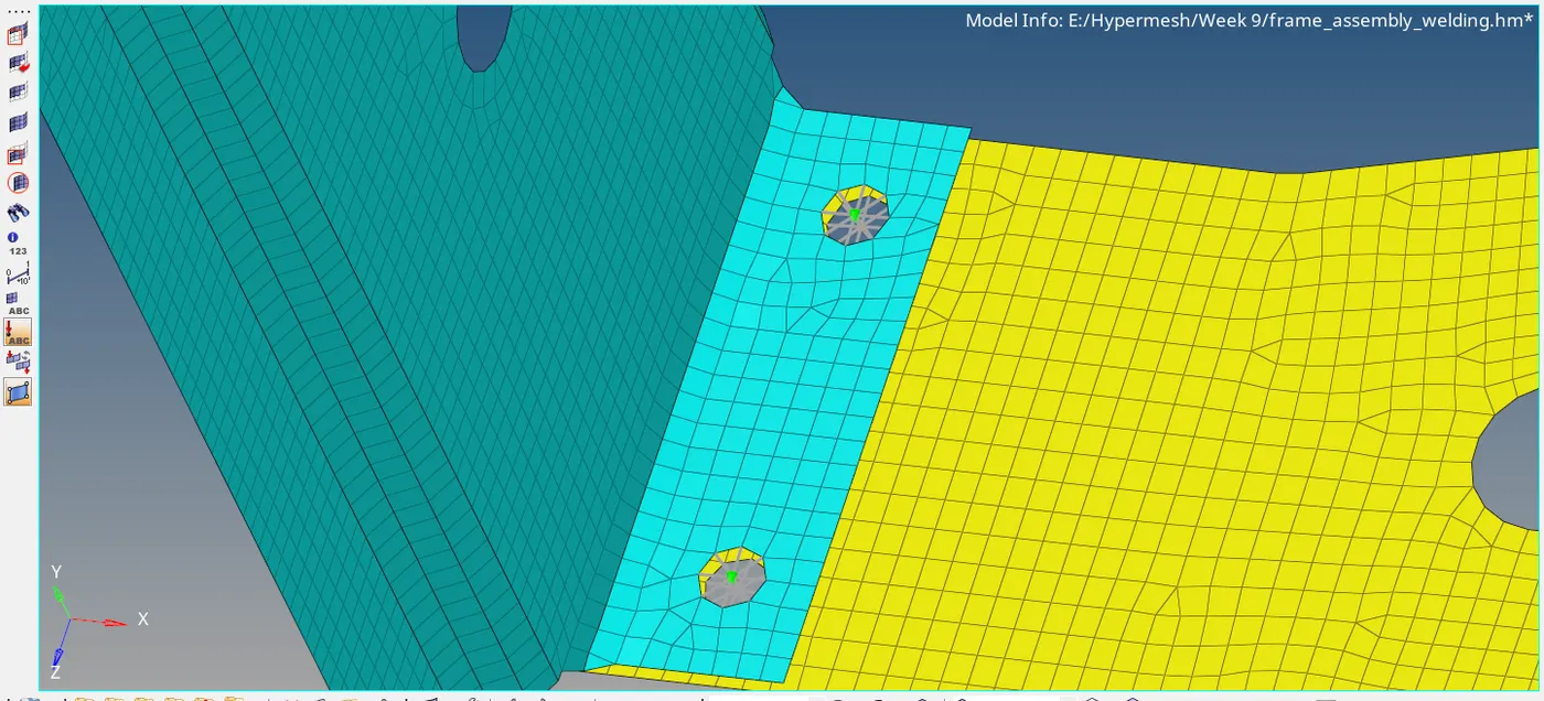
Similarly connect Rear_truss_2 & Right_Rail_2 using Bolt Connector.
Now we have to connect Front_truss_2, Front_truss_1 & Right_Rail_1 using Spot weld with 3 Layers and 5 mm Diameter. We will create them one by one. First we will connect the Front_truss_1 &
Right_Rail. Go to 1D > connectors > spot. Under location selector, Select the displayed nodes. Select Front_truss_1 & Right_Rail_1 components under connect what selector. Set number of layers = 2
and search tolerance as 5 and type as weld and diameter as 5. Click on create. The connectors are created and realized.
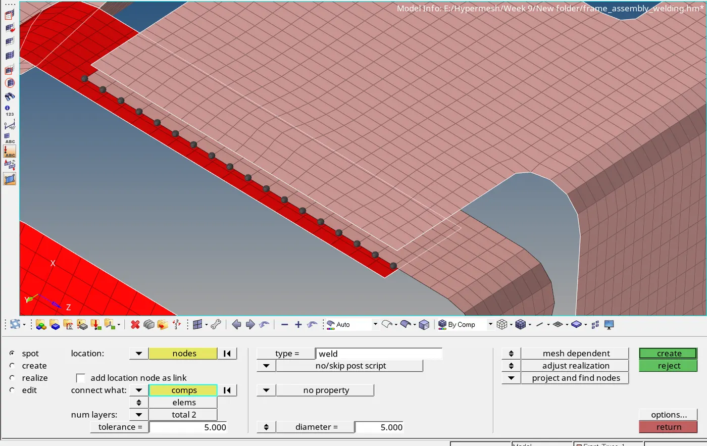
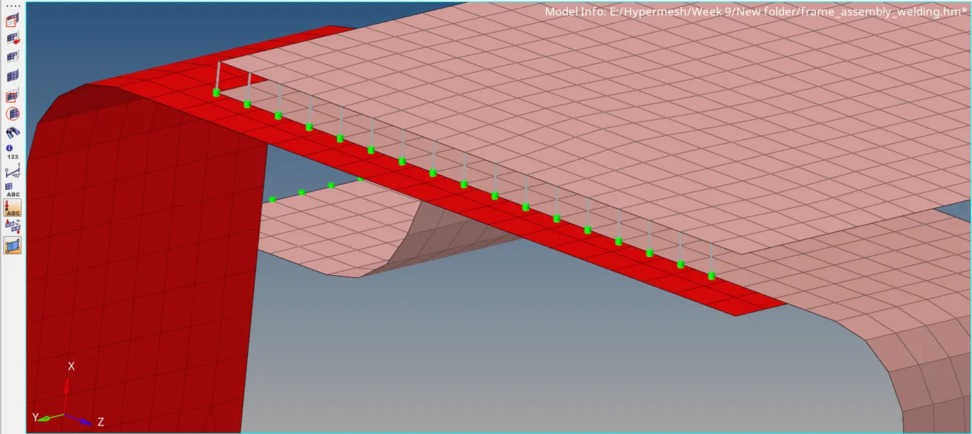
Similarly connect the Front_truss_2 & Front_truss_1.
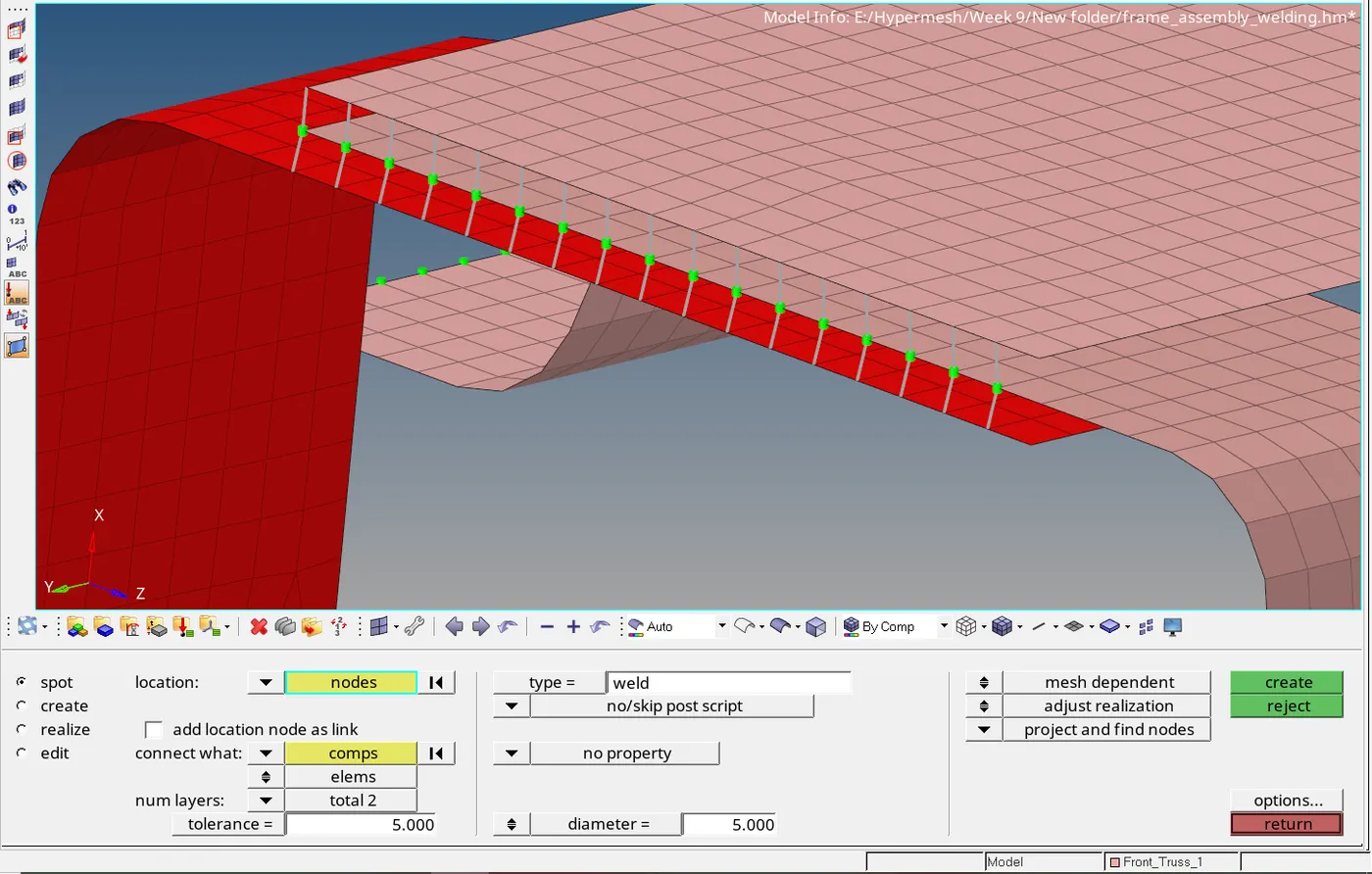
Now connect Front_truss_2, Front_truss_1 & Left_Rail_1 using Hexa (Adhesive). First, we will connect Front_truss_1 & Left_Rail_1 and then we will connect Front_truss_1 & Front_truss_2.
Go to 1D > connectors > seam. Select the displayed nodes of Front_truss_1 and select the Front_truss_1 & Left_Rail_1 under connect what components. Keep search tolerance as 5 and type as Hex
(adhesive). Keep strips & coats as 3 and with as 4. Click on create. The connectors are now created.
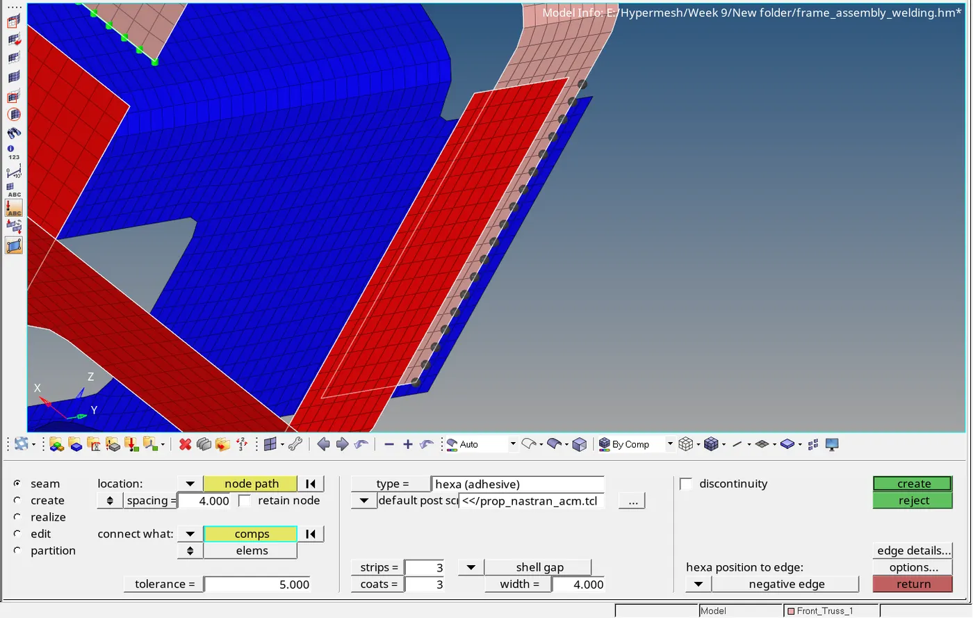
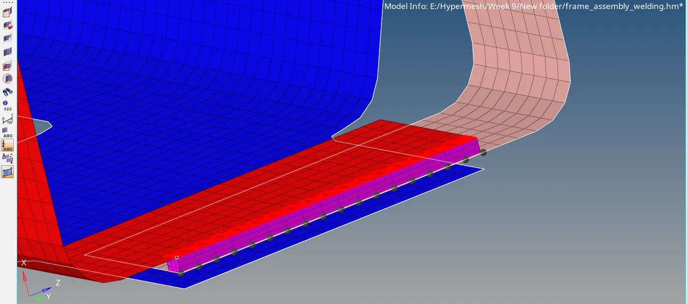
Using similar procedure, connect Front_truss_1 & Front_truss_2.
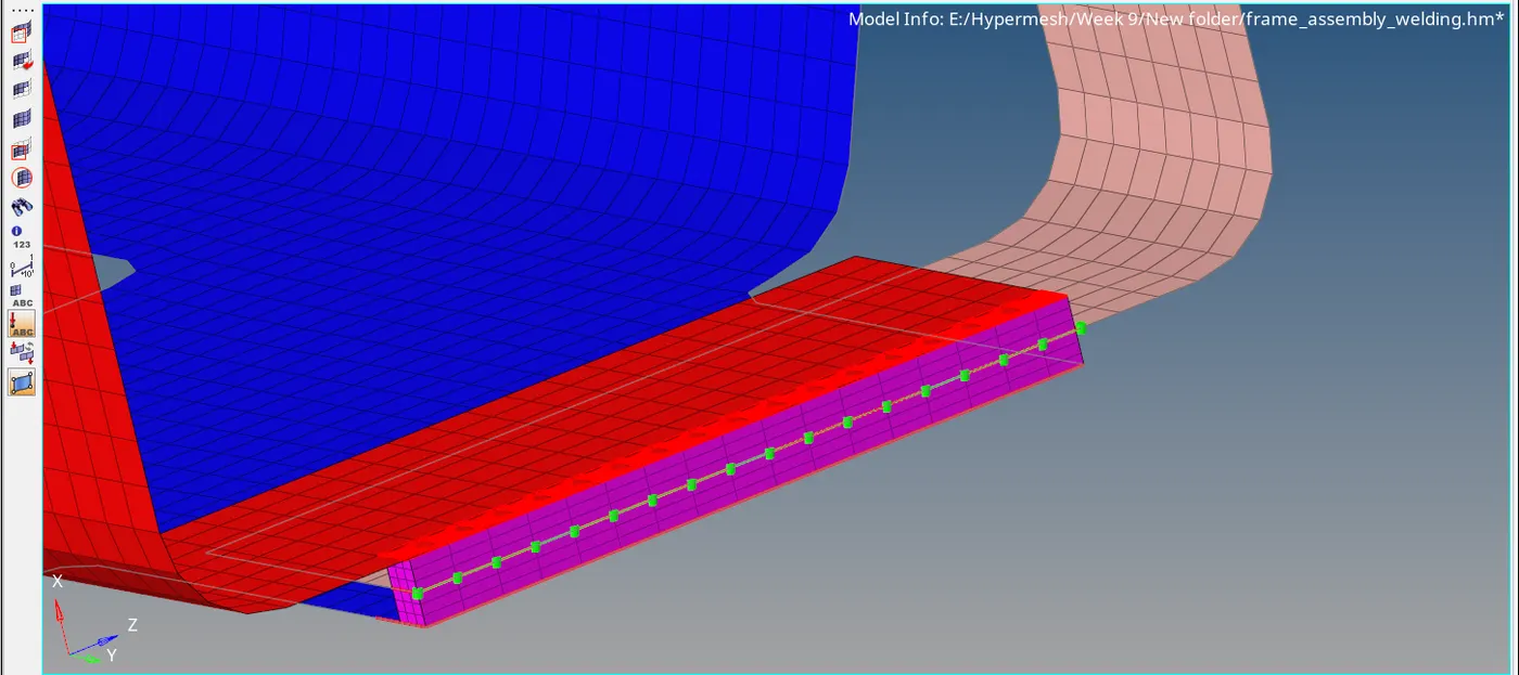
Now for remaining components connect them with suitable conections.
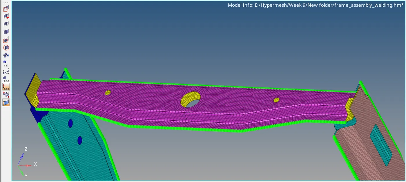
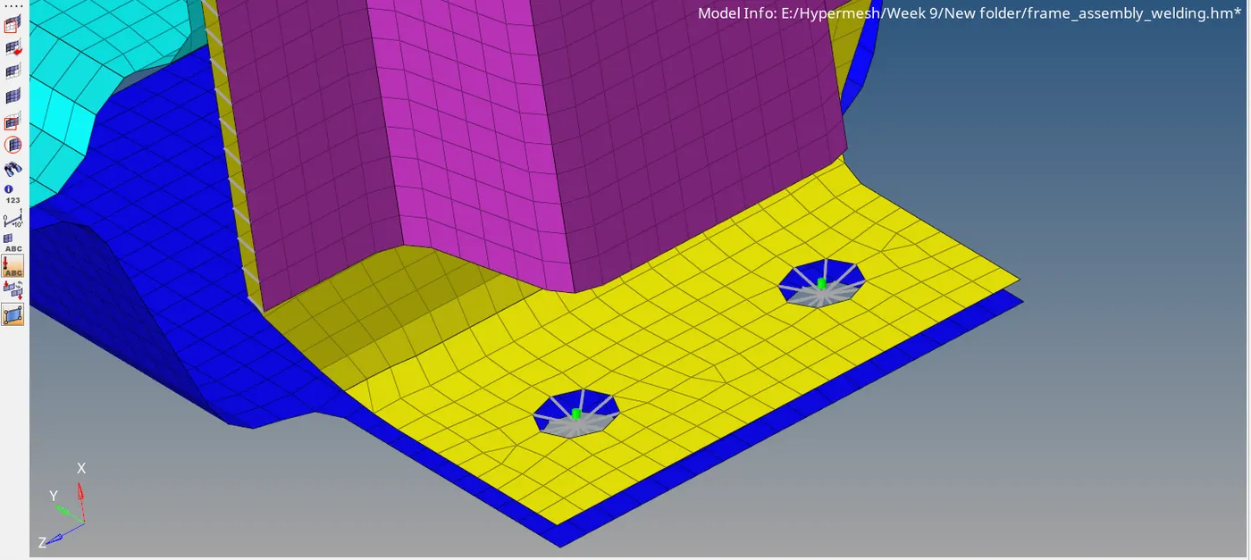
Thus, all the components were connected.
- Conclusion: Under this challenge, we have learned how to make connections like spot, seam, bolt between the components using connectors making sure that theconnectors are realized and how to debugg
unrealized connectors.