Week 8-Challenge
- Objective: To create Tetramesh for Housing using following criteria -
Elements sizes: Min- 2mm
Target- 5mm
Max- 7mm
Tet collapse≥">≥ 0.15
For other components, they are to meshed using target size of 6mm and Tet collapse≥">≥ 0.15
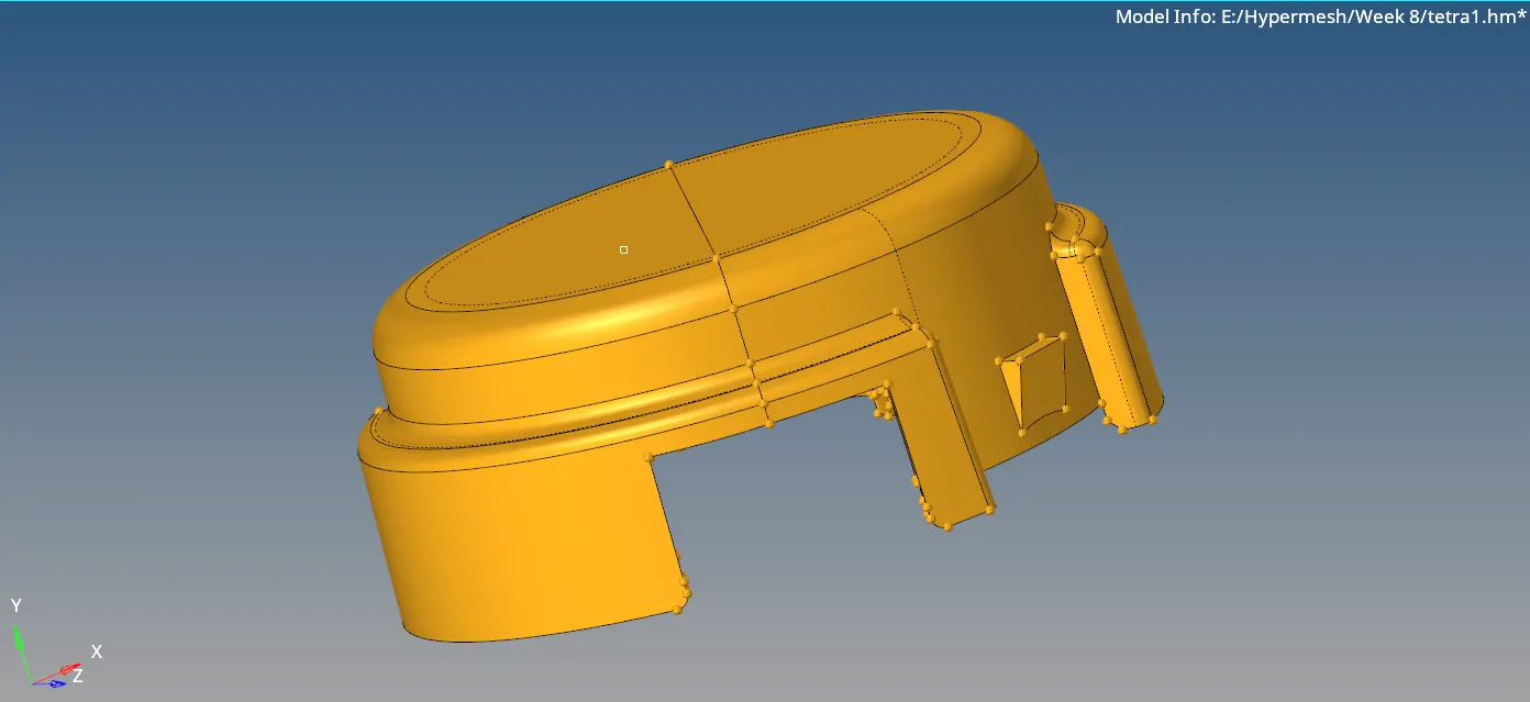
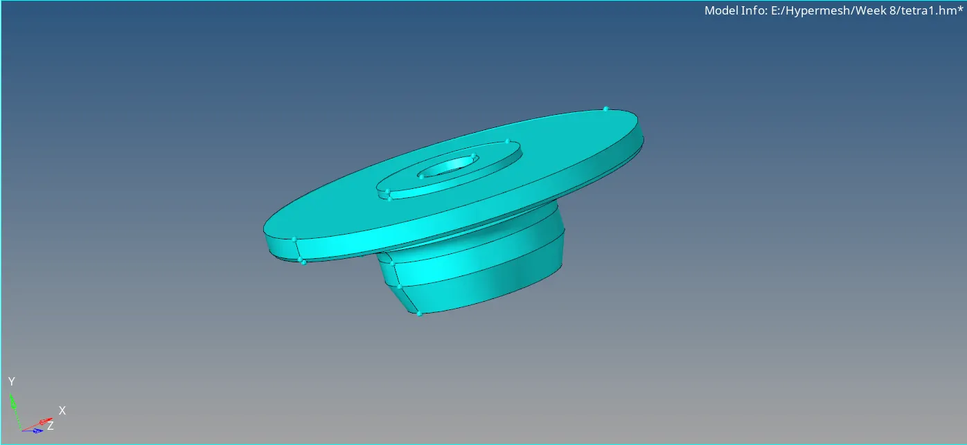
- CAD Model:
- Procedure:
Import the component. Go to File > Import > Geometry. Set the file type to STEP and open the CAD file. Set the Geometry color mode to By Topo.
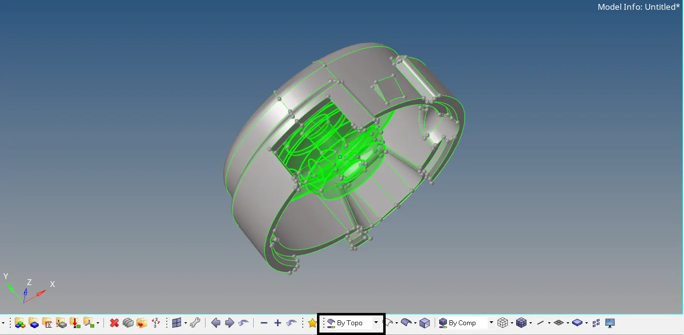
The Model component is a surface component and the Model2 is a solid component as indicated. Isolate the Model component and make it current component.
No free edges are found in the component. We can now perform geometry cleanup. Toggle all the edges where the elements may fail for max or min element size.
Go to Quick Edit panel > Toggle edge. Click on the edges to be toggled.
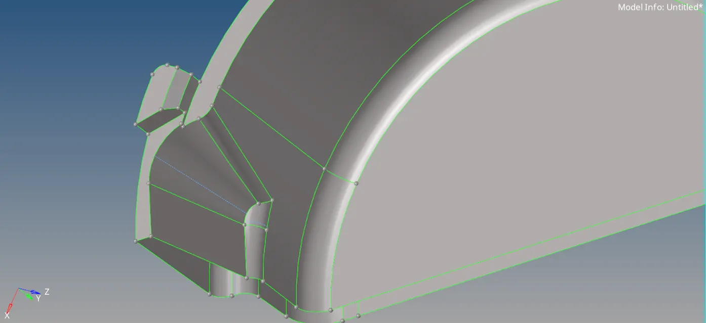
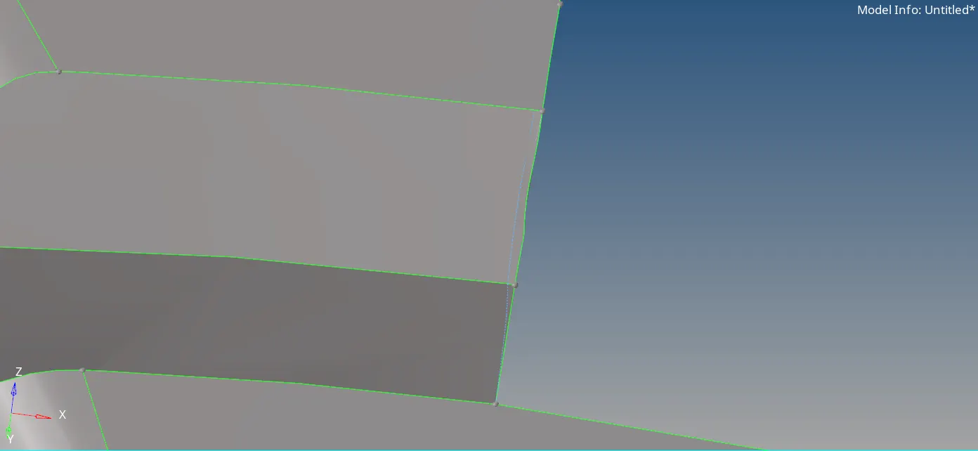
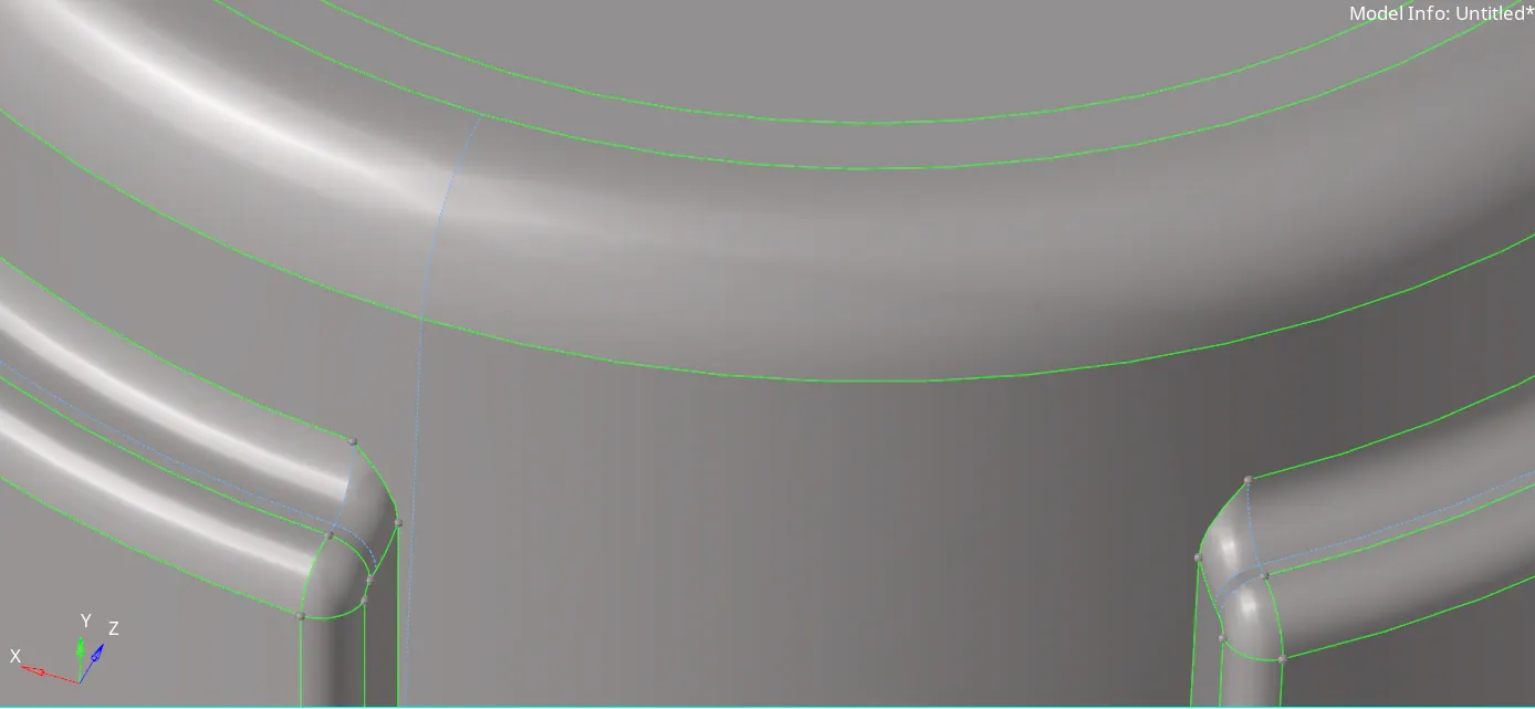
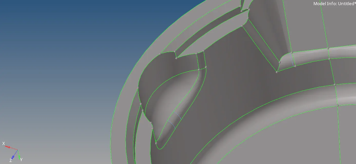
Now we can mesh the component. Go to 2D > automesh. Set element size = 5 and mesh type to Trias. Select the displayed surface and click on mesh. The component now will be meshed with
2D tria elements.
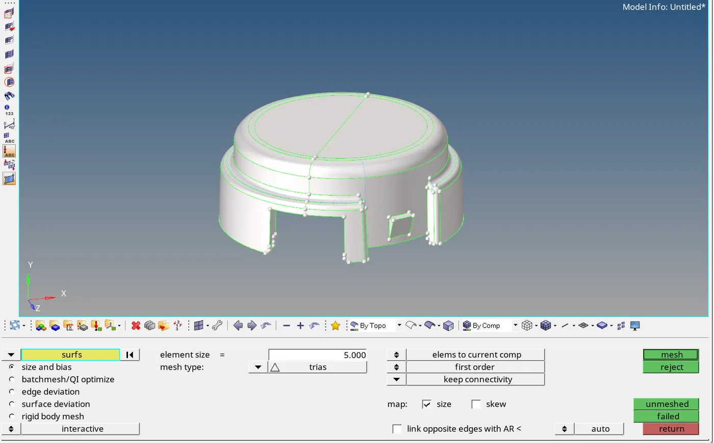
The component will be meshed with 2D tria elements. Now check for elements failing for min and max element size. Go to Tools > Check elements > 2D.
Check for elements failing for max and min element size. We can easily repair the elements failing the quality criteria by remeshing the failed elements with the adjacent elements or also by using
the distance option and ajust the distance between two nodes.
After cleanup of the failed elements, we can proceed to tetrameshing. Go to 3D > tetramesh > tetramesh parameters. Set Max tetra size = 7, Min tetra size = 2 and tet collapse > 0.15.
Now go Tetramesh > Fixed trias/ quads to tetramesh. Set entity selector to element and select the displayed elements. Click on mesh. Now the component will be meshed with tetramesh.
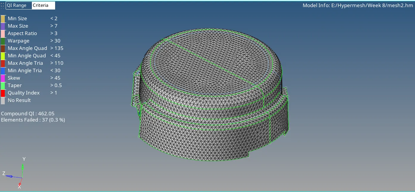
Now we can check the elements for tet collapse. Go to Tools > check elemens > 3D > Tet collapse. Set value to 0.15 and click on tet collapse. Failed elements will be highlighted. No failed elements
are found.
Now isolate the Model 2 component and make it current component. Since this is a solid component, first we will delete the solid. Press F2 and set entity selector to solid. Select displayed solid and
click on delete.
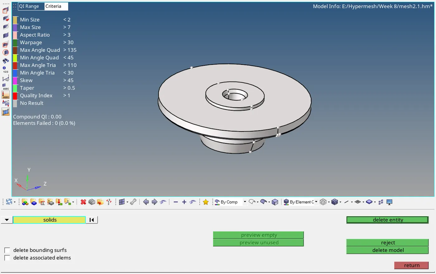
Only the surface will remain now. No free edges are found in the component.
Let us perform geometry cleanup. Toogle unwanted edges.
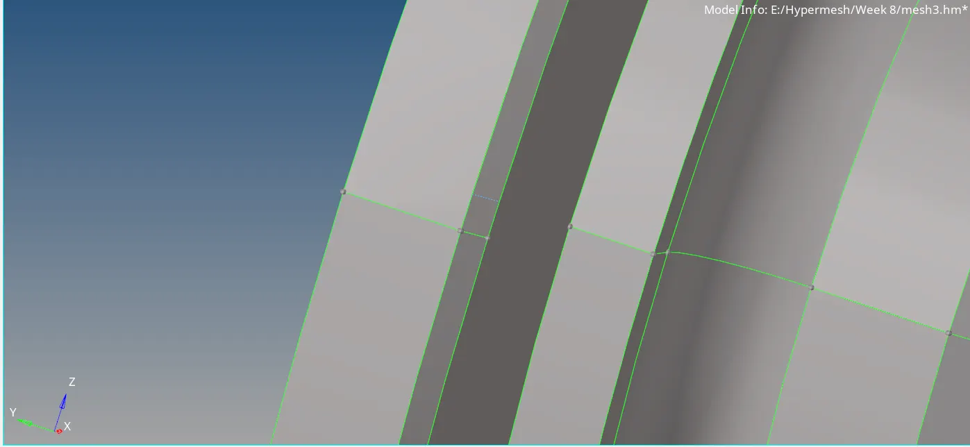
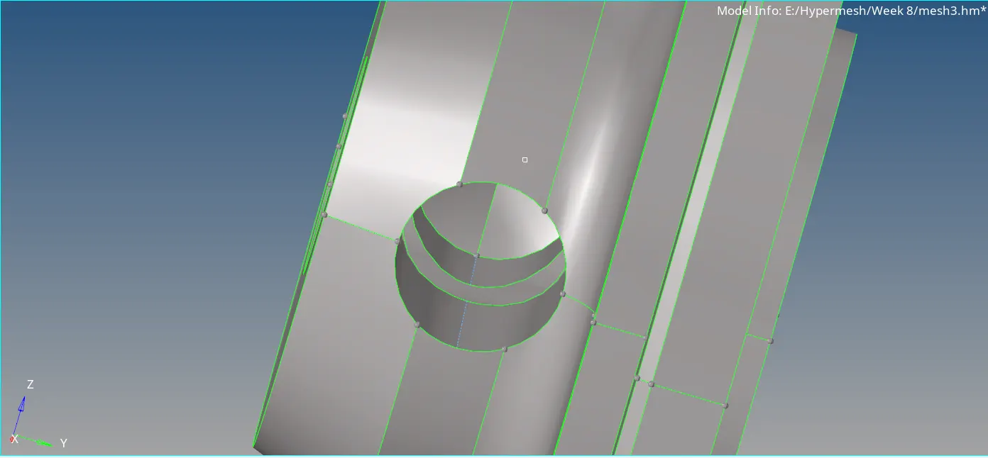
Now we can mesh the component with trias. Go to 2D > automesh > surf > displayed. Set element size = 5 and mesh type to tria. Click on mesh.
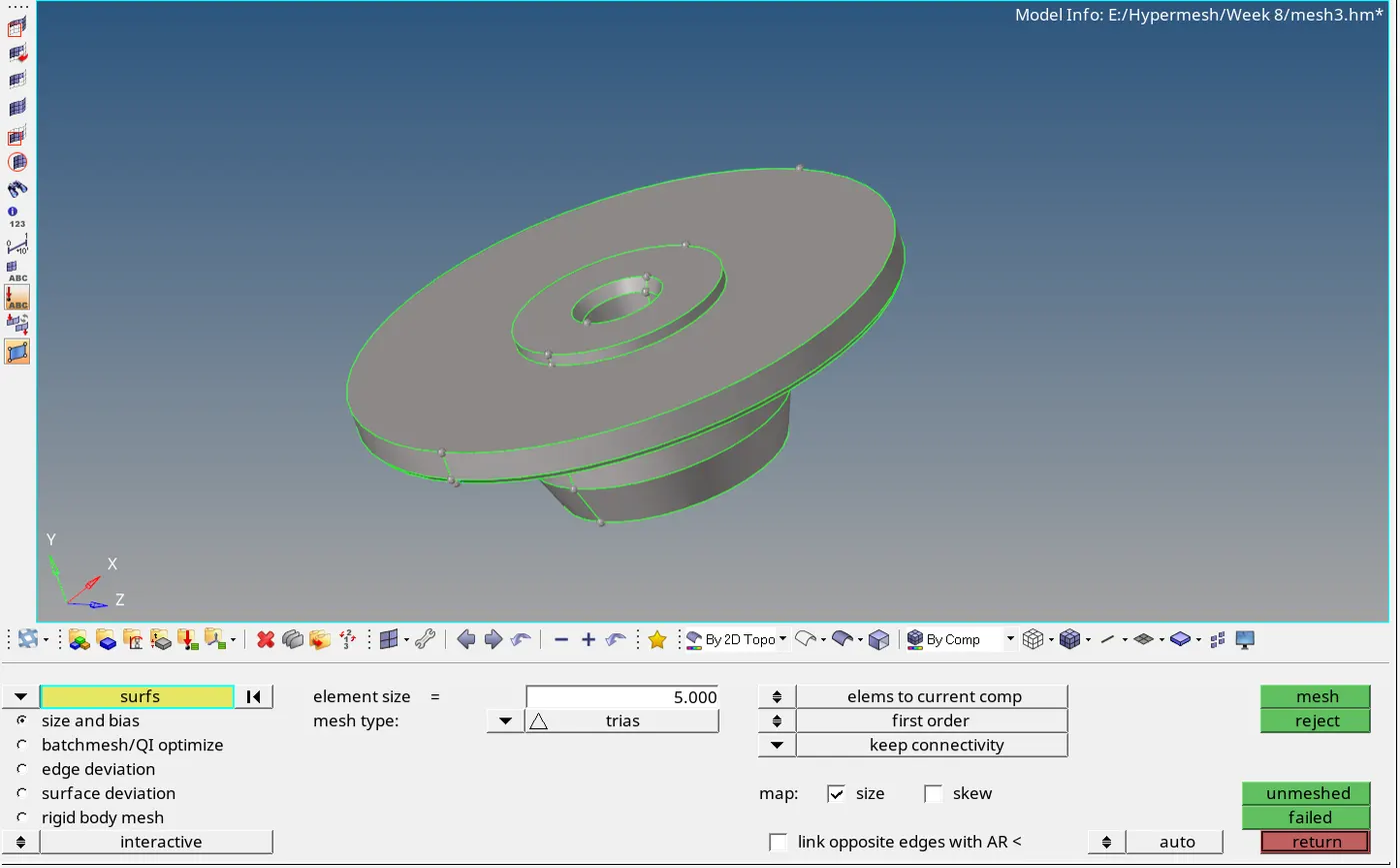
The component will be meshed. Now we can check the elements failing for max and min elements size. Go to Tools > check elements > 2D. Click on max element size. Failed elements will be
highlighted. Click on save failed.
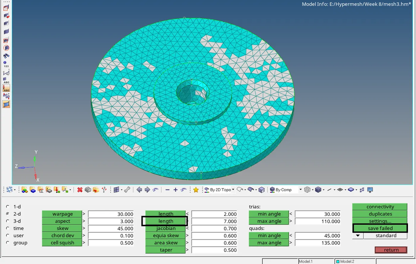
Now we can clean up these failed elements by remeshing or adjusting distance between two nodes using Geo > distance option. Press F5 to enter mask tool. Set entity selector to elements and click
on retrieve. Now click on mask and then click on reverse. Now only the failed elements will be visible. Click on unmask adjacent icon elements to unmask adjacent elements.
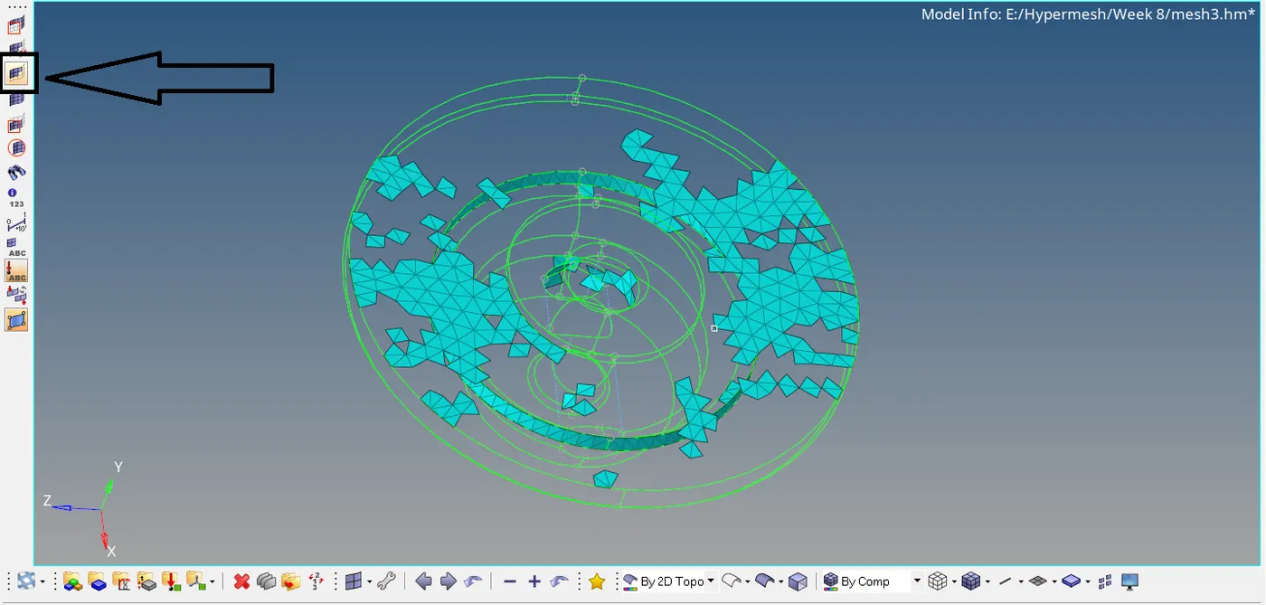
Now remesh failed elements or adjust the distance between two nodes to clean up the failed elements.
After cleanup of failed elements, we can perform tetra meshing on the component. Go to 3D > tetramesh > fixed trias / quads to tetra mesh. Under element selector, Select the displayed elements.
Click on mesh.
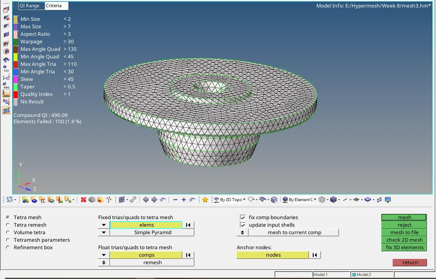
The component is now meshed with tetra mesh. Now check for tet collapse of the elements. Go to Tools > check elements > 3D > tet collapse. No failed elements for tet collapse are found.
Now let us import the chassis assembly file. There are total 8 components in it. We will mesh only the 4 components since the other 4 are symmetric and we wont reflect the elements considering the
node count for student version. We will perform Quick tetra mesh for these components. We can delete the solids.
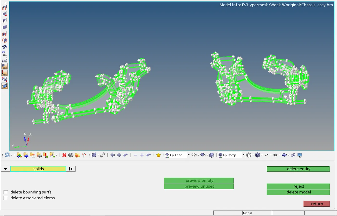
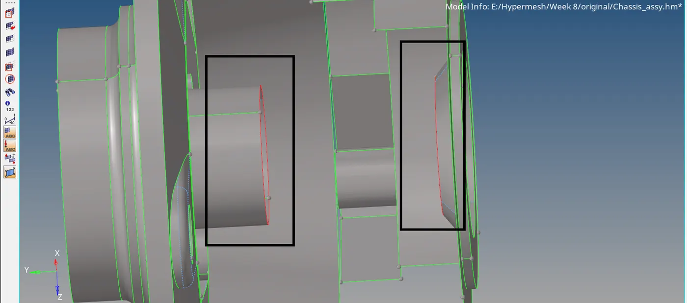
Isolate the hub component. As shown below, there are teeth in these components. We will remove these teeths so that the quality failing elements are reduced for 3D mesh.
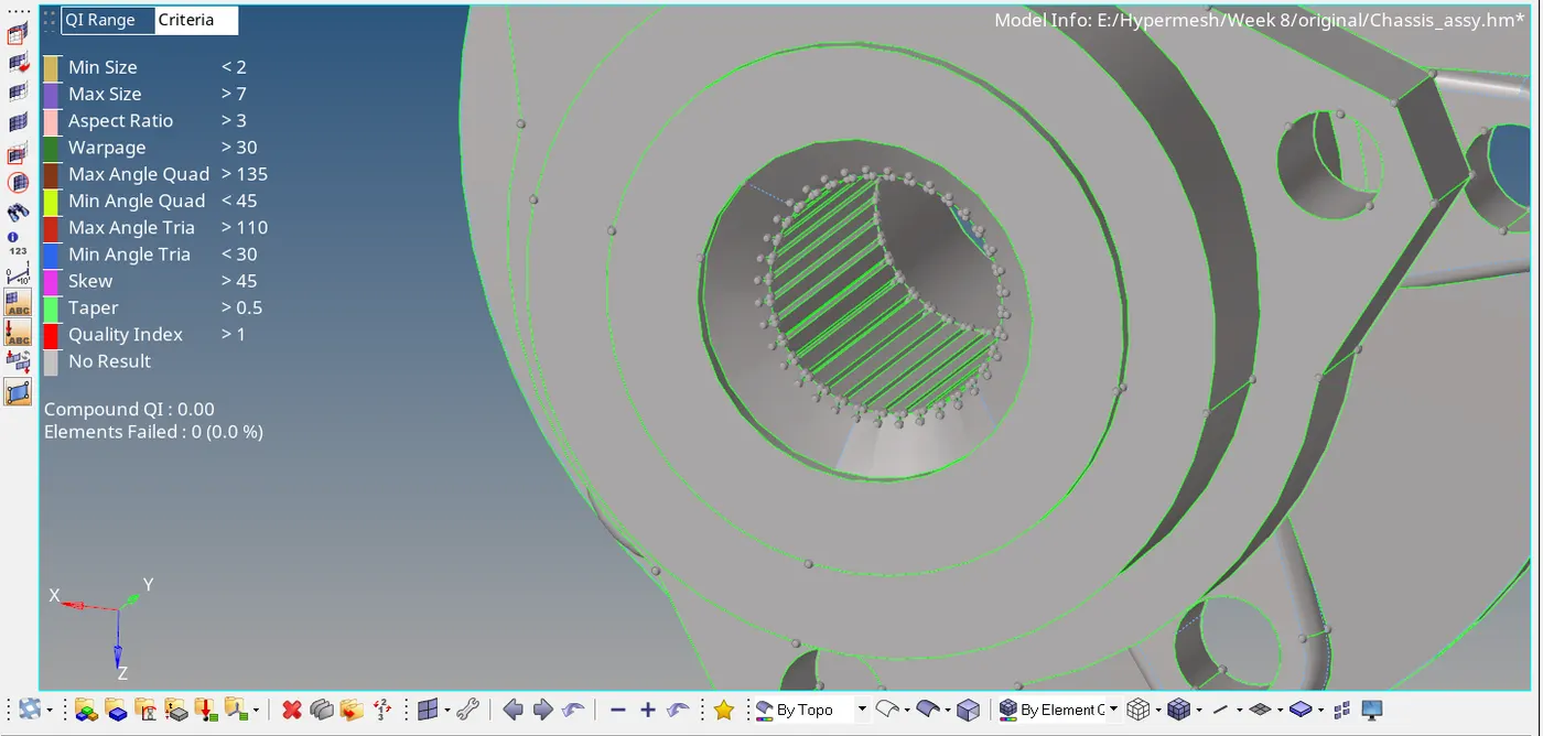
Split the surface as shown below and isloate the teeths so we can delete them without any accidently involving unwanted surface.
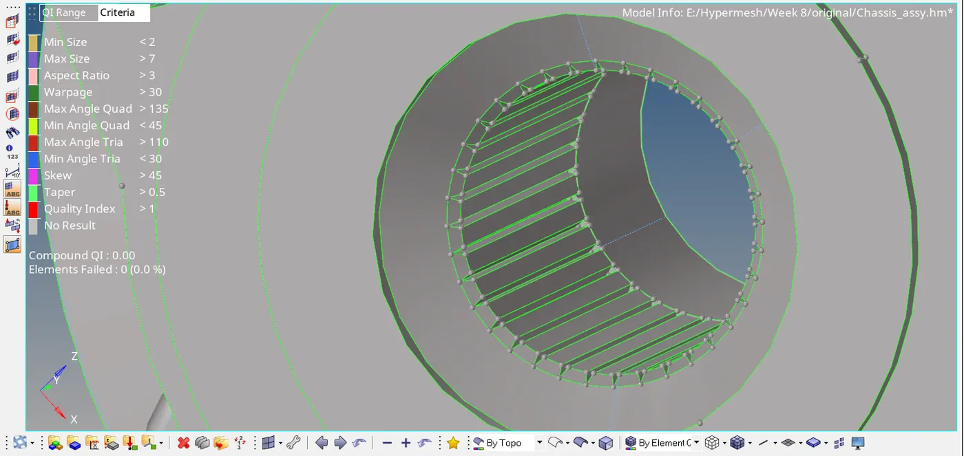
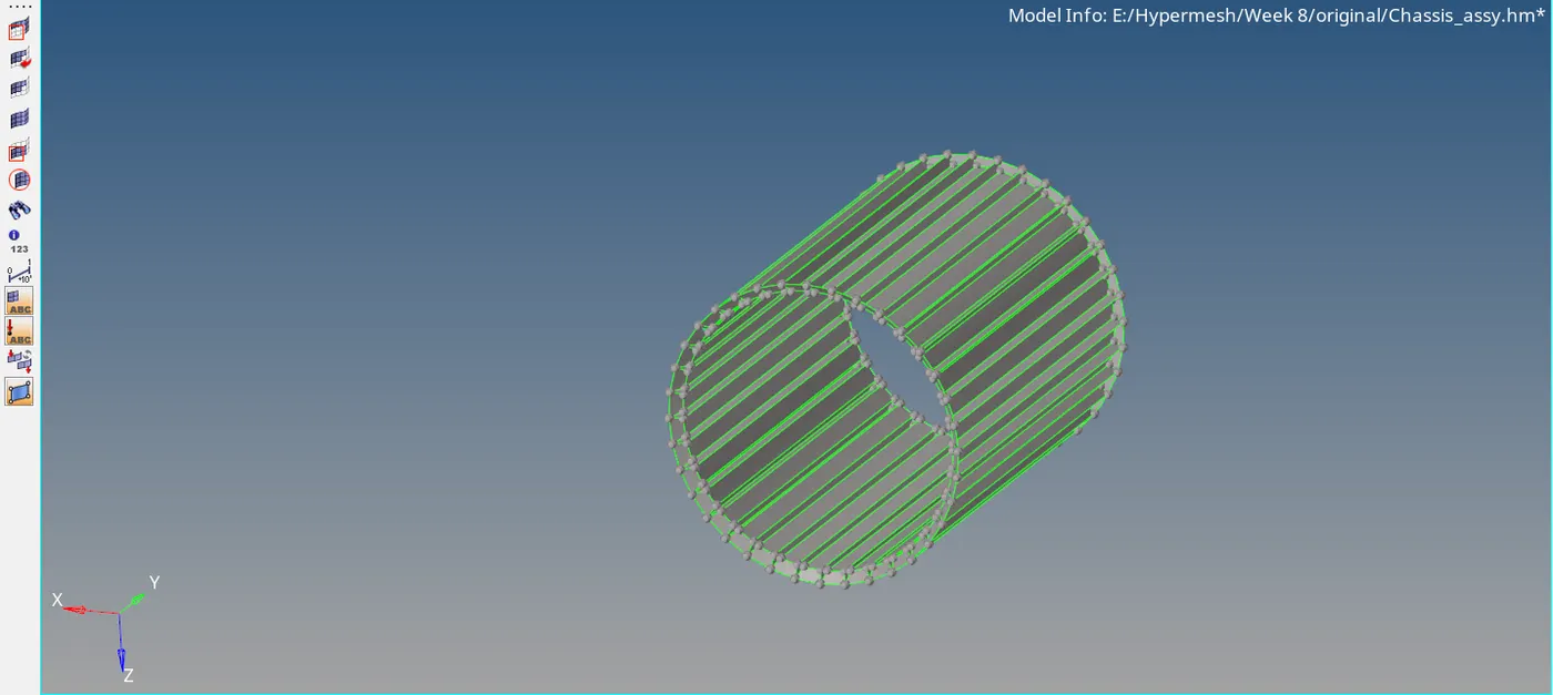
Now we need to connect the two shown surfaces as we have deleted the teeths.
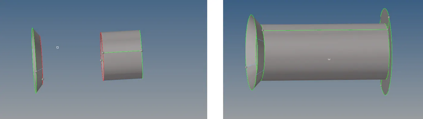
Perform geometry cleanup. Toogle unwanted split surfaces or feature lines that could distort proper mesh flow. Refer below for the same.
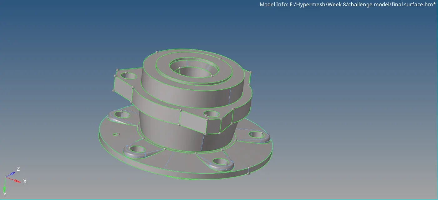
Now the component is read to be meshed. To mesh the component, go to View > HyperMesh > Utility.
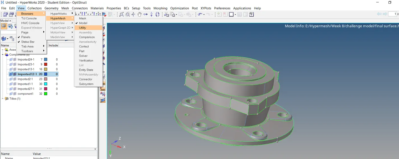
Click on the Geom / Mesh. Then select Quick TetraMesh.
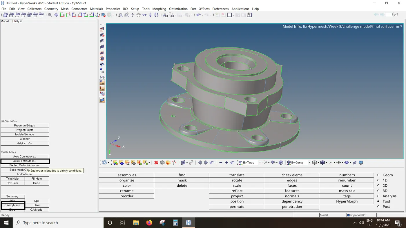
In the Volume complist, select the hub component. Enter the mesh size = 6 and mesh type to trias only. Click on mesh. After completion of meshing, popup window will occur indicating that mesh is
completed.
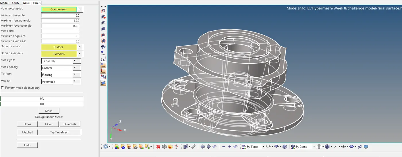
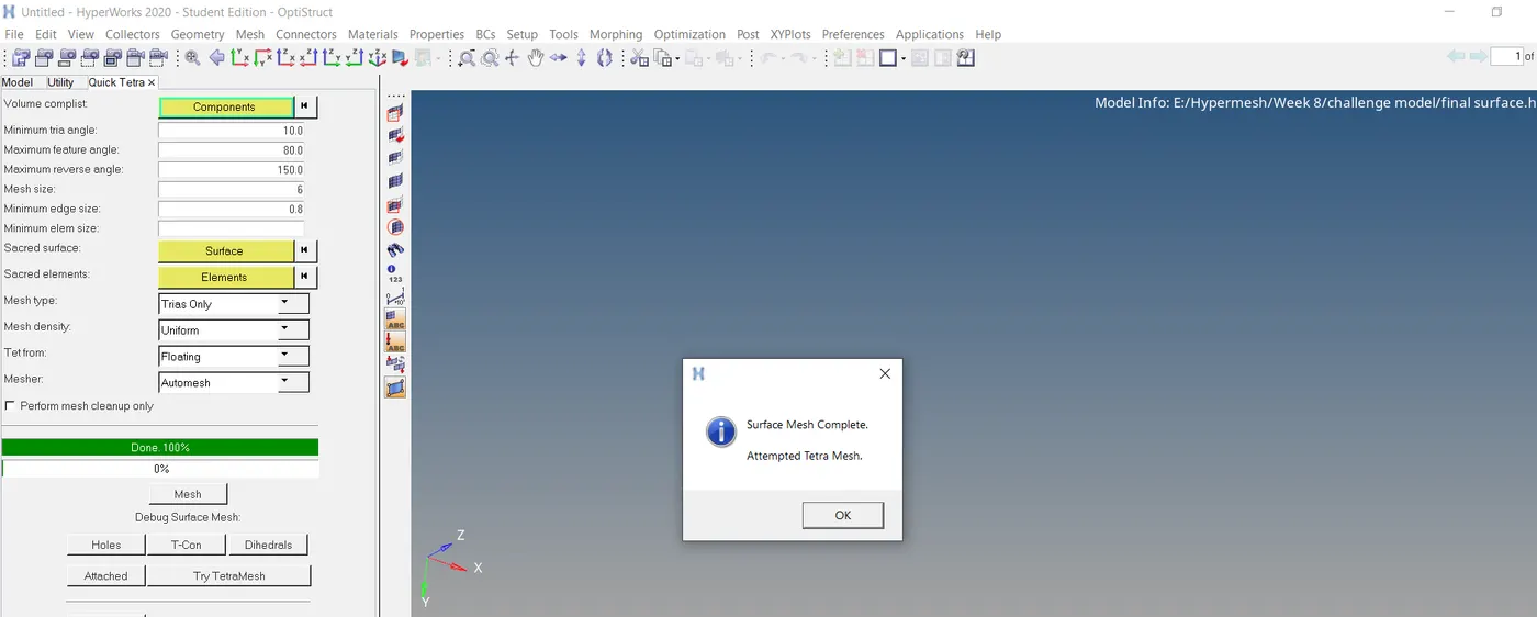
The component is now meshed. We can verify this by masking few elements. As we know, Quick Tetramesh performs surface mesh first and then attempt tetra mesh, there are shell elements produced
in the original component collector containing the surface and new component is created where the 3D elements are stored.
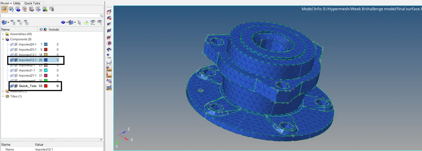
Now we can check for Tet collapse which is an important quality check for 3D elements. Go to Tools > check elements > 3D > tet collapse. Enter tet collapse value as 0.15. Click on tet collapse. All the
elements with tet collapse less than 0.15 will be highlighted. 77 elements are found to be failing for tet collapse.
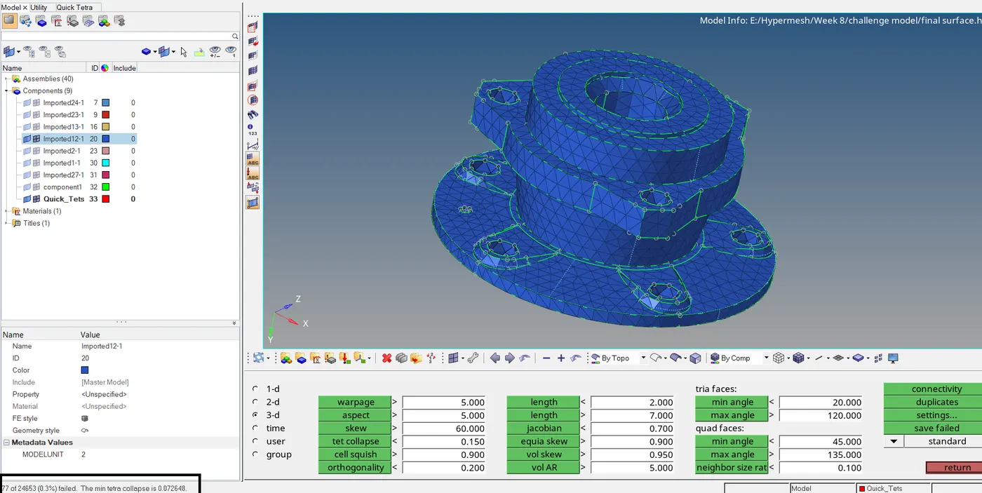
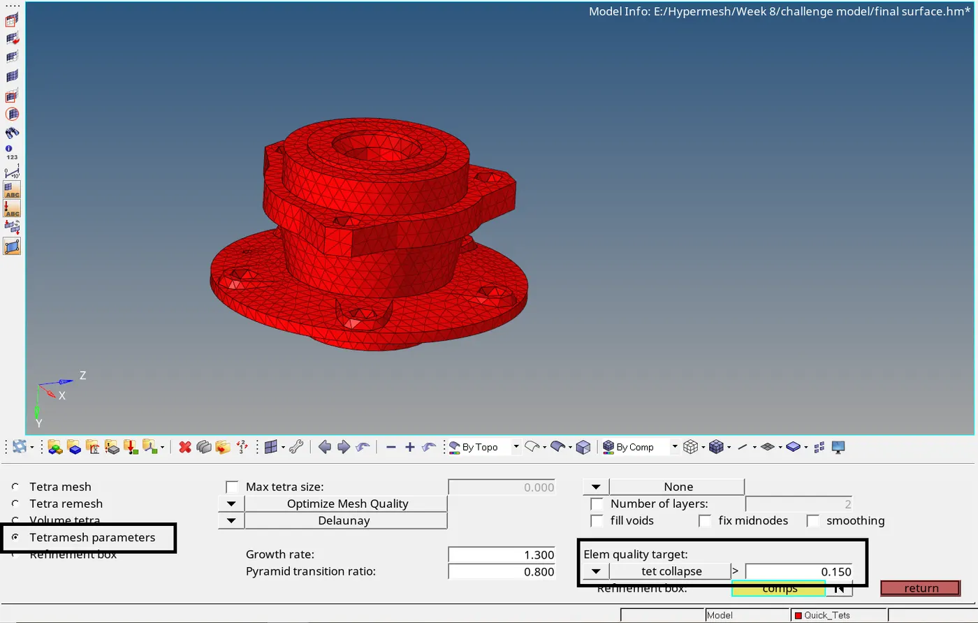
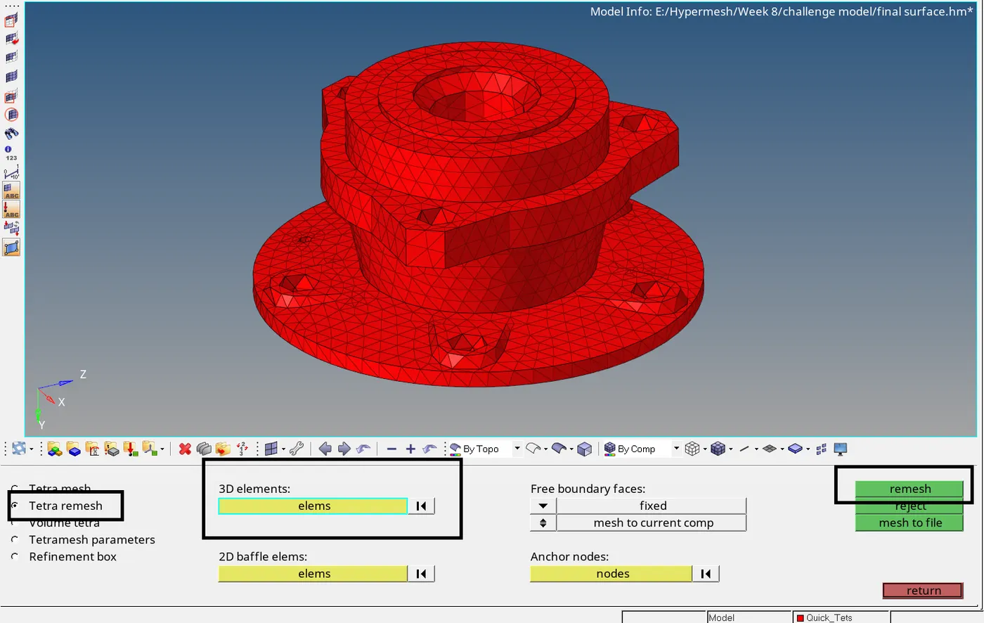
Let us try remeshing the elements to repair failed elements for tet collapse. Go to 3D > tetramesh > tetramesh parameters. Enter tet collapse value > as 0.15. Again go to Tetra remesh option. In the
3D elements entity box, select 3D elements using displayed option. Click on remesh. The elements will be remeshed considering the entered tetramesh parameter for tet collapse.
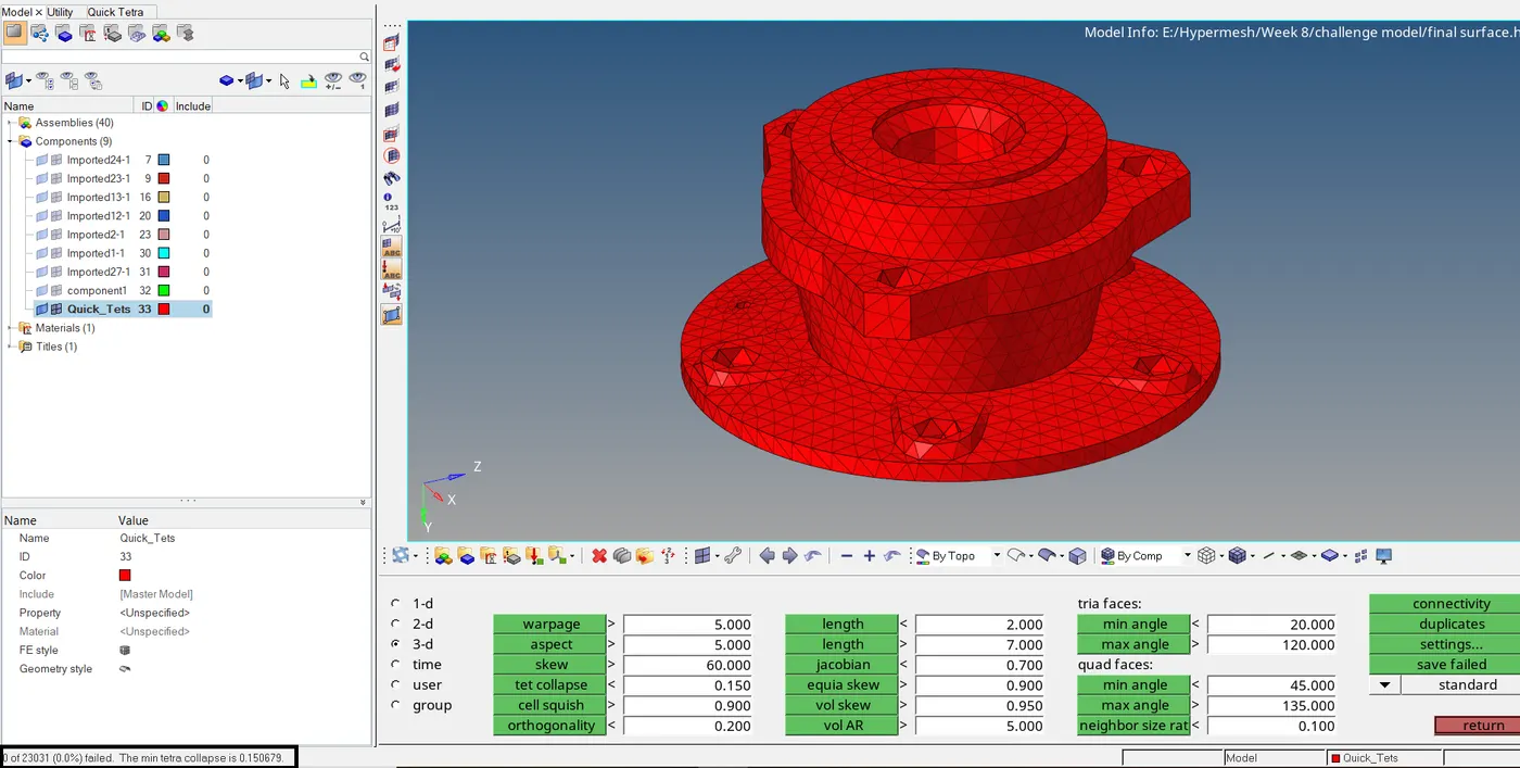
After remesh is completed, again check the elements for tet collapse. This time 0 elements are found failing for tet collapse.
Now we can delete the shell elements from the original component and move the 3D elements in the original component using organise tool.
Using above procedure, we can mesh the other components and remesh the components failing for tet collapse.
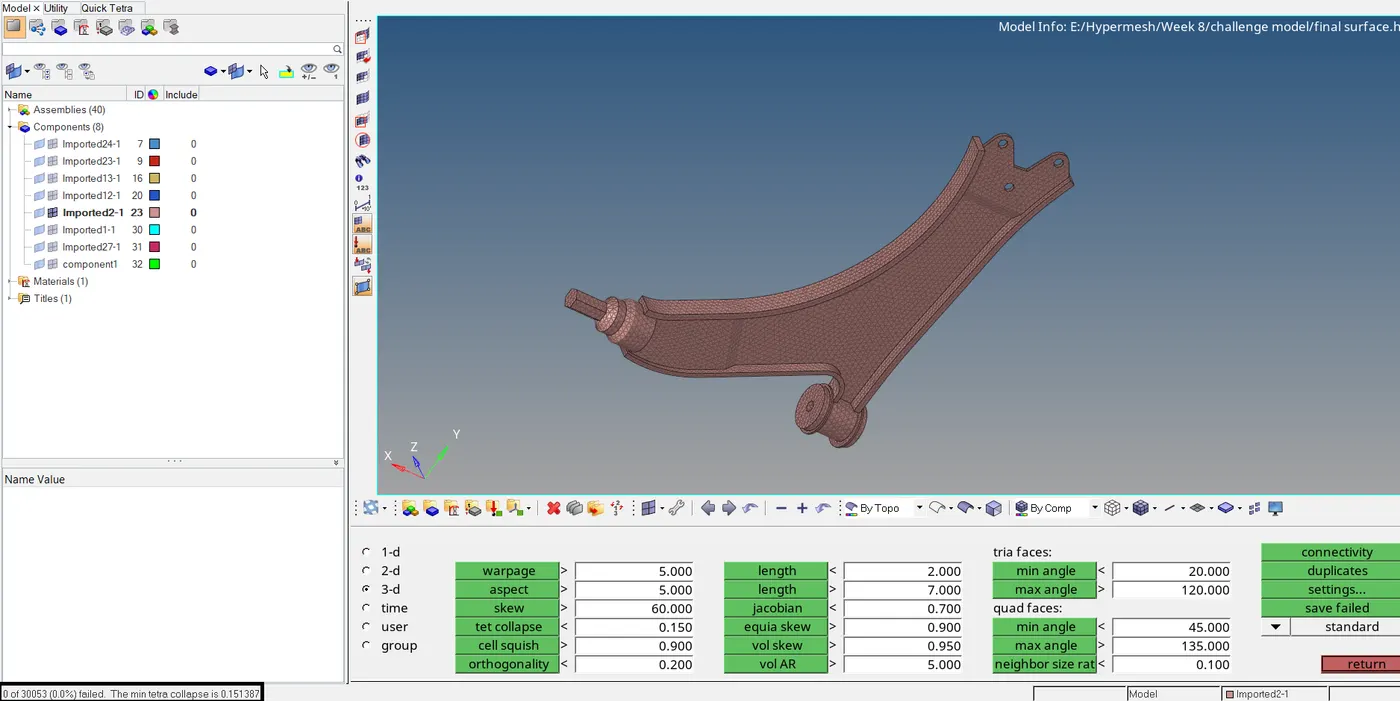
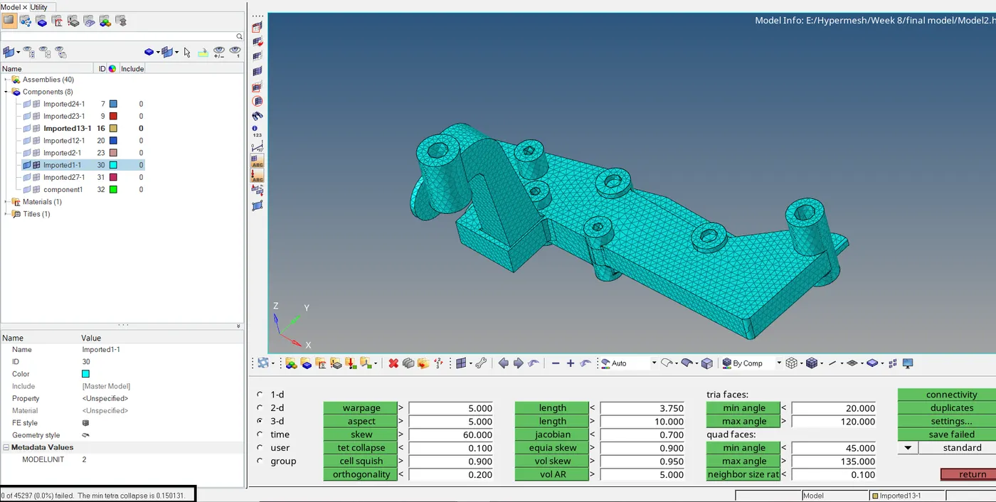
For the knuckle component, we cannot use Quick Tetramesh due to errors in geometry. The component has penetrating surfaces, thus we will have to perform volume tetramesh. We will perform volume
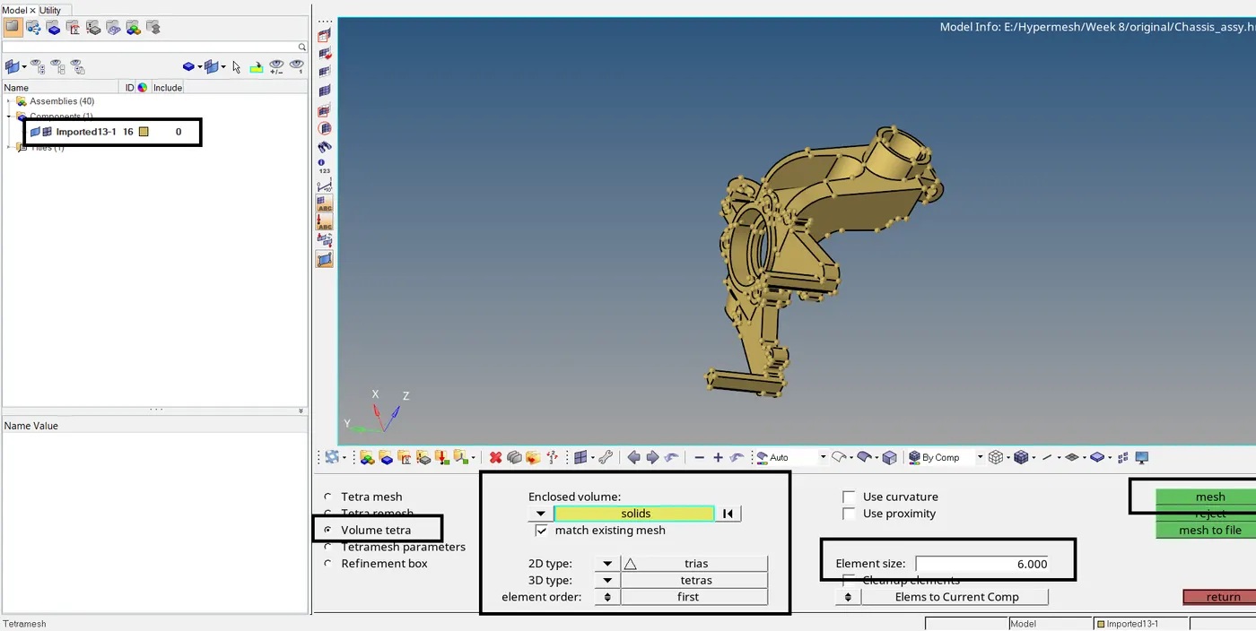
tetramesh in original file containing the solid and import the FE model in our file since we have deleted the solid component. Save the current file.
In the original file, delete all the components except the knuckle. To perform volume tetra, go to 3D > Volume tetra. In the entity selector, select displayed solid. Set 2D element type to trias and 3D
element type to tetras. Element size as 6. Click on Mesh. The component now will be meshed.
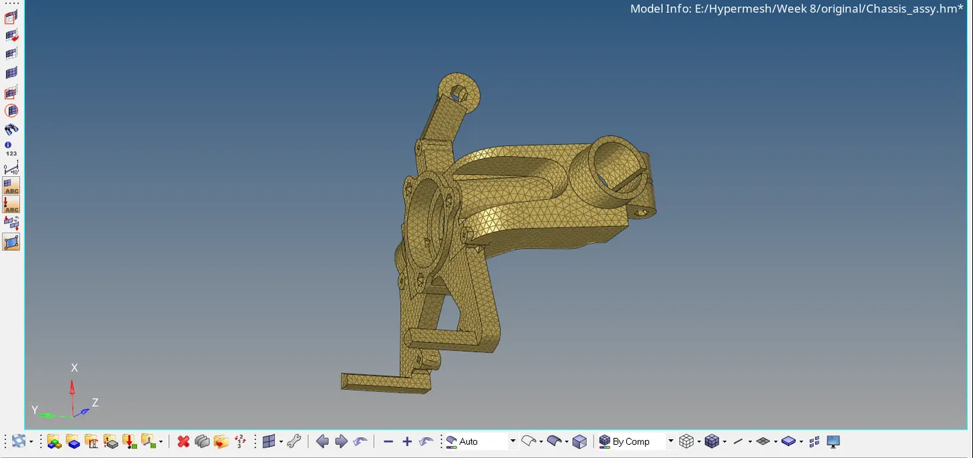
Let us check for tet collapse for the knuckle component. 300 failing elements are found.
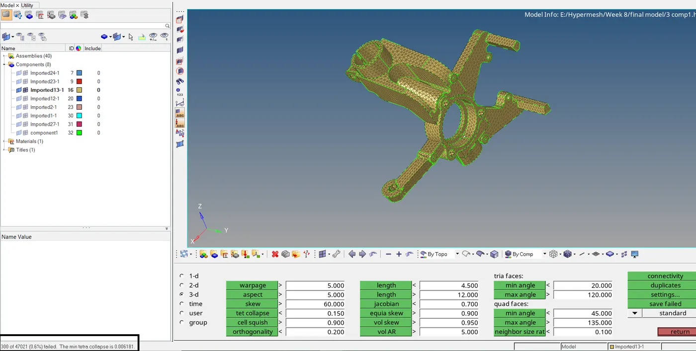
So we have to remesh the elements now to reduce failing elements for tet collpase. After remeshing, the number of failed elements are reduced to 90. Again remeshing the failing elements did not reduce
the failing elements in greater count, so we need to manually repair the failed elements. We can use the translate tool to adjust the height of the tetra element, so that they wont fail for tet collapse. Mask
the failing elements and retreive them and isloate them.
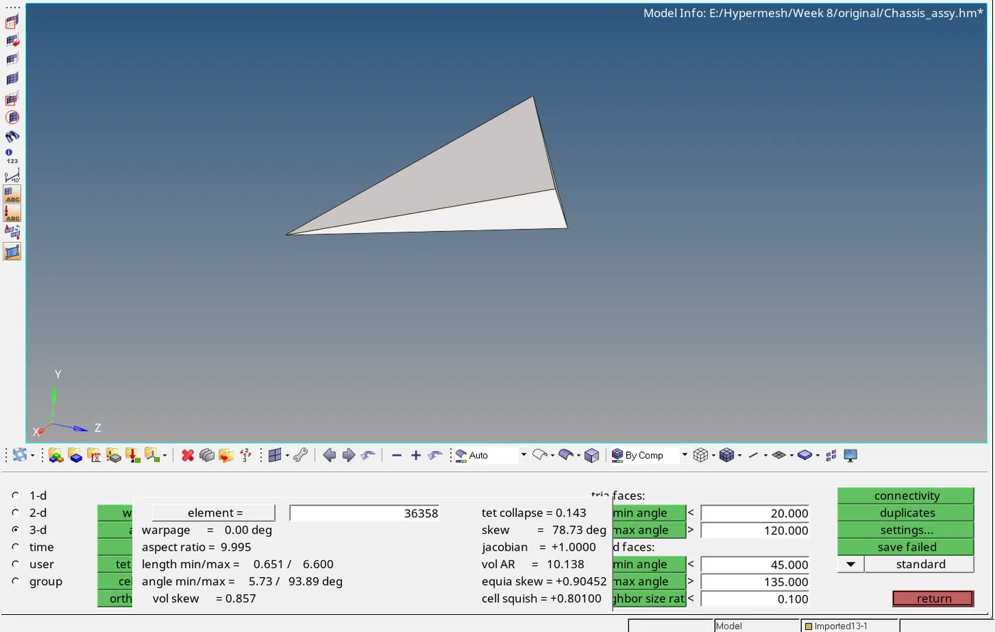
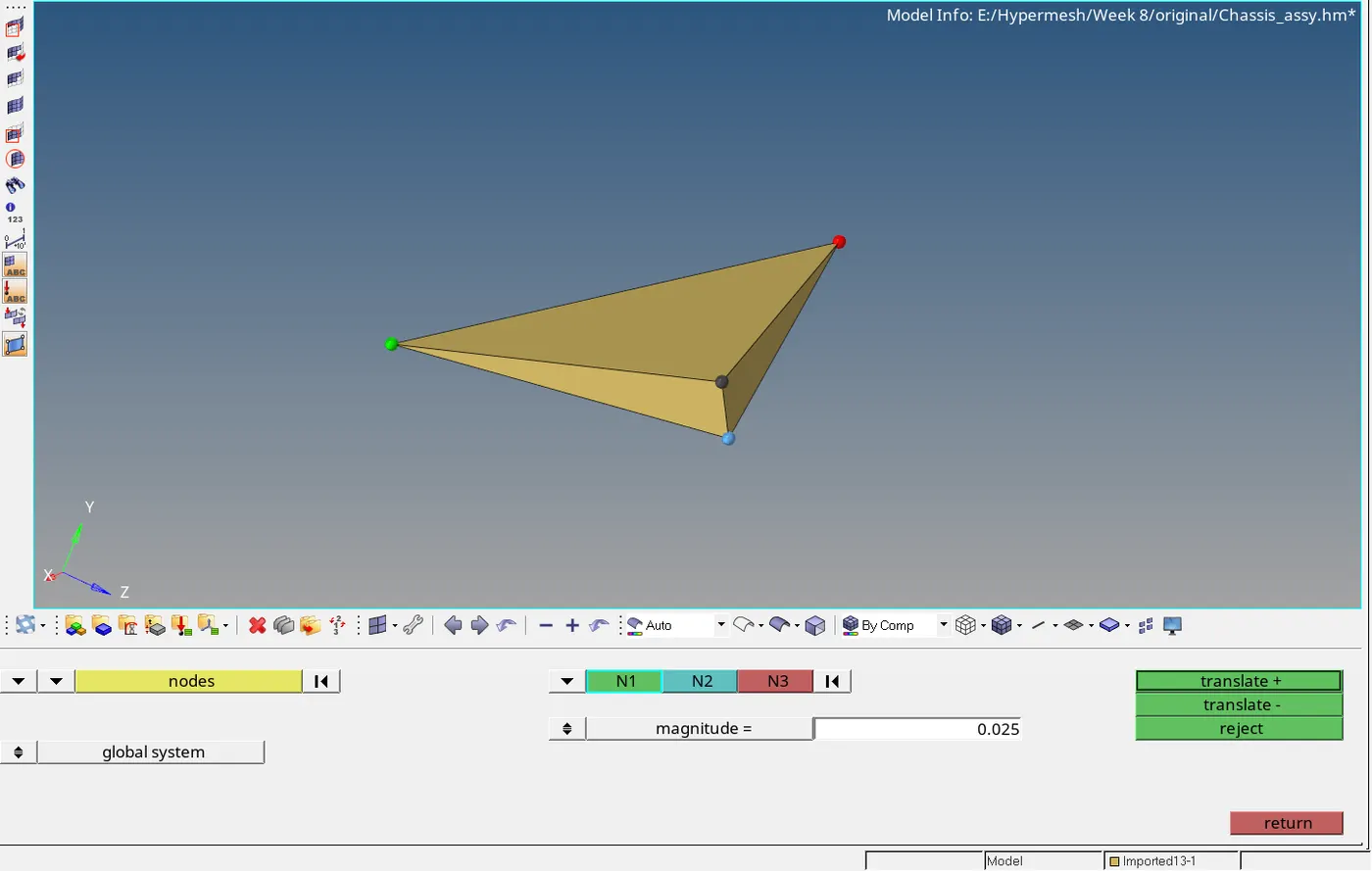
This element has tet collapse of 0.143. Now adjust the height of this element to increase the tet collapse. Go to Tools > translate. Select the shown node to adjust the height. Select the base nodes as
N2, N2, N3. Enter magnitude = 0.025. Click on Trasnslate to adjust height until min tet collapse of 0.15 is achieved.
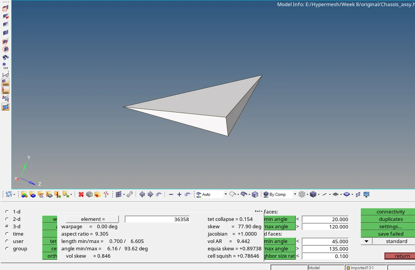
Now the element is repaired fo tet collapse. Similarly, repair all the failed elements.
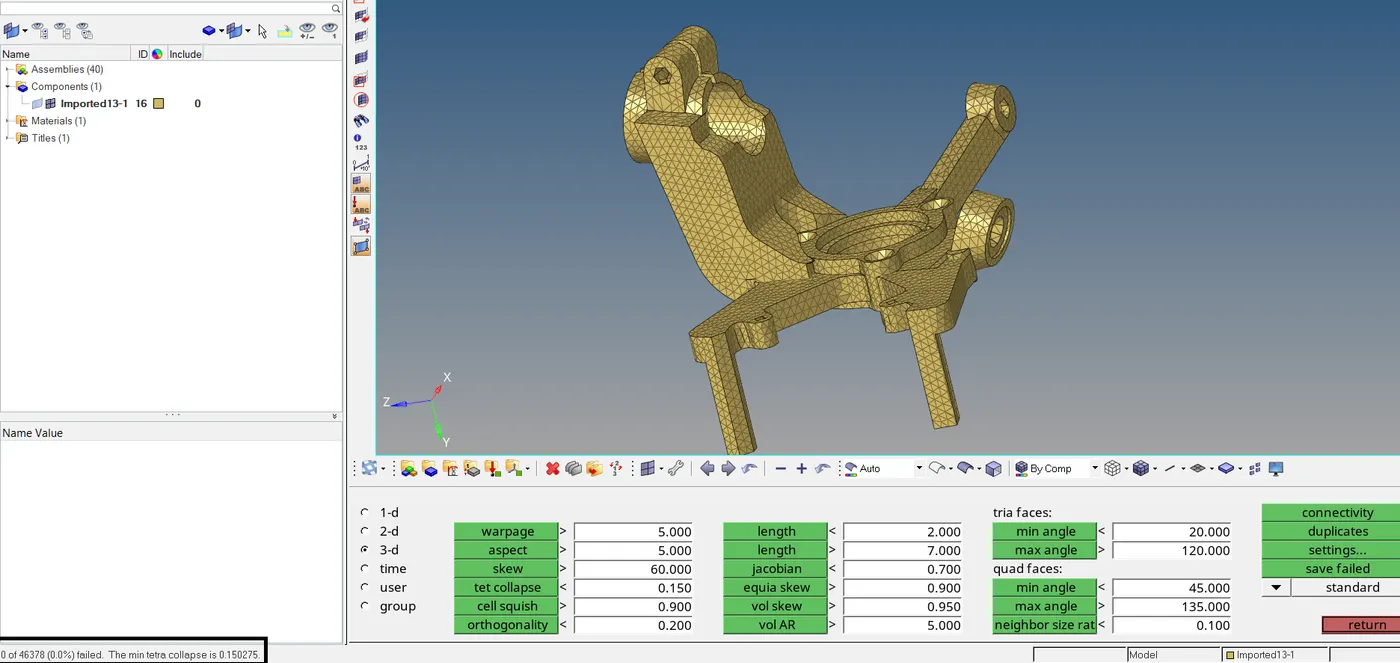
Now delete the solid and after that the surface of the component. Keep only the FE model and save the file. Now open the previous saved file and import the now saved model in this file. Now we have the
surface and FE models of all the components of chassis assembly.
For the crank housing component, we can use 2D to 3D method. After meshing only one element was found failing for tet collapse which was repaired.
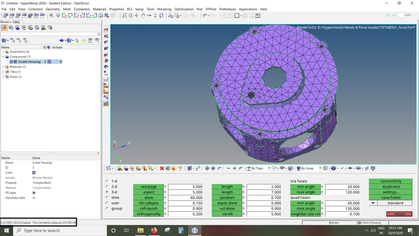
- Conclusion: Thus we have performed tetrameshing on the given components using 2D to 3D method, Quick TetraMesh and Volume Tetramesh. We have also learned how to repair elements failing
for tet collapse by remeshing Tetramesh using Tetramesh parameters and using the translate tool.