Week 12 - Project-1
- Note: The resolution of the attached images are automatically reduced, so the image quality is reduced.
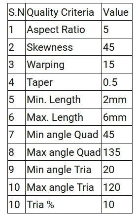
- Objective: Follow the Quality Criteria and mesh the given component and assign thickness.
-
Target Element Length = 4mm
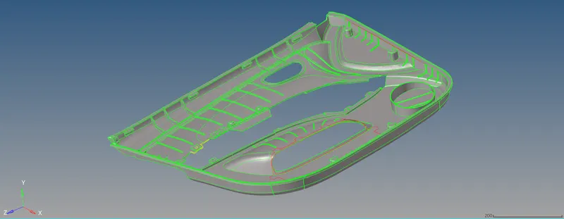
- CAD Model:
- Procedure:
Import the given CAD model. The given component is an plastic component having variable thickness, so we will extract the mid surface manually. First, we will split the component into 4 parts for
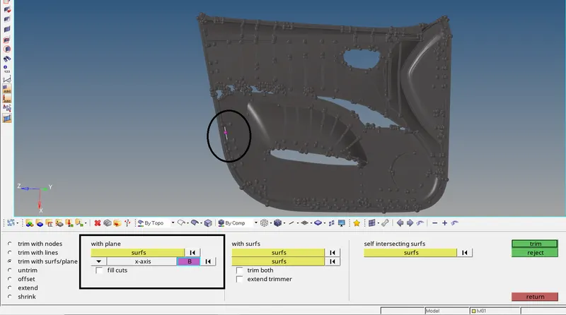
simplification of work. Go to Geom > Surface edit > Trim with surfs/plane > with plane. In the entity selector, select the displayed surface. Set Z axis and base point as shown below and click on trim.
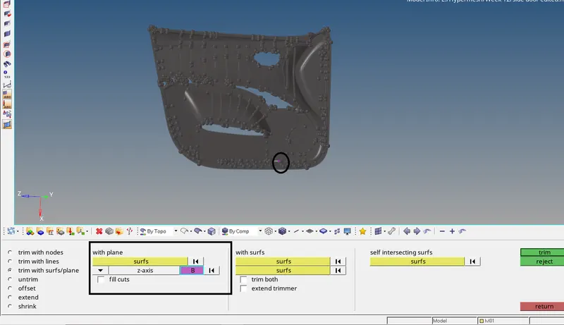
The component will be now splited perpendicular to Z axis i.e along the X axis through the base point.
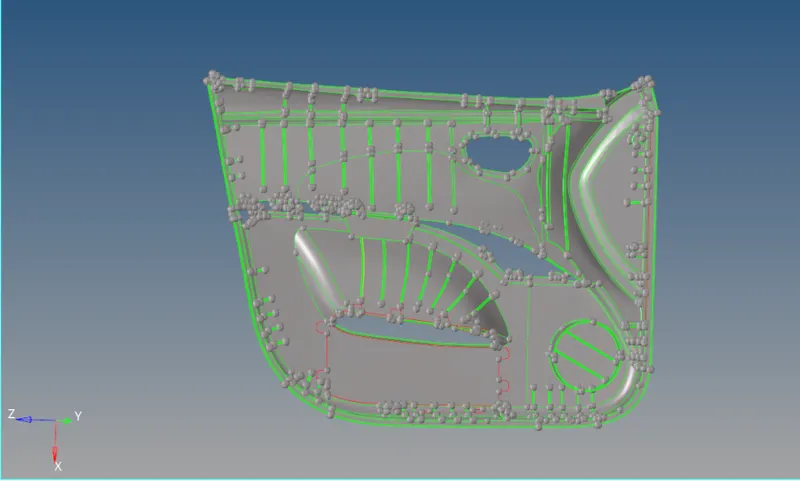
Similarly, split the component now along the horizontal direction.
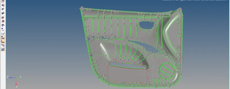
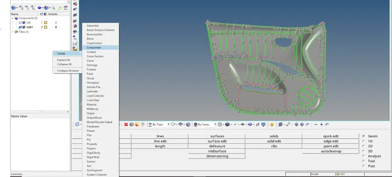
Now the component is splited into 4 parts. Now move the splited 4 parts of the component into 4 different components. For that create 4 new components. To create new component, Right click on the model
view > create > component. A new component will be created. Create remaining three components.
Now move each splited part of the component into different created component. To move the splited part of the compoment into newly created component, go to Tools > organize > collectors. Set the
entity selector to surfs. Select the displayed surface. In the dest component tab, select component1 and click on move.
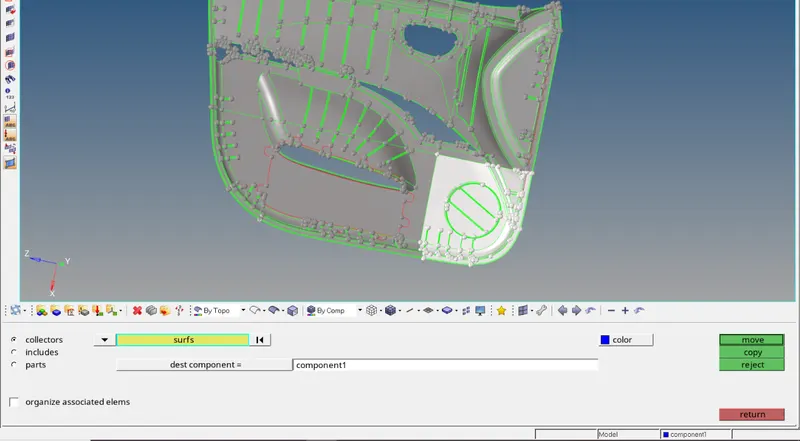
The select surface is now moved to the component1 collector. In similiar way, move the remaining three components to the 3 remaining newly created component.
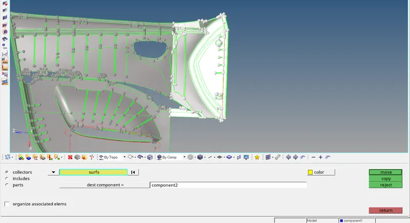
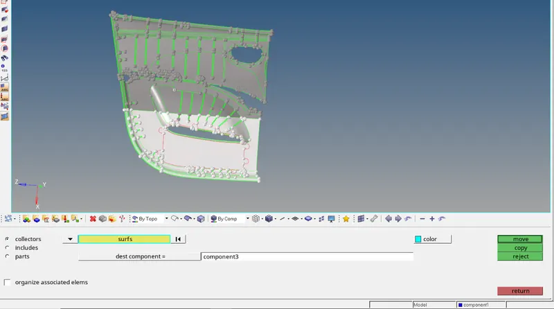
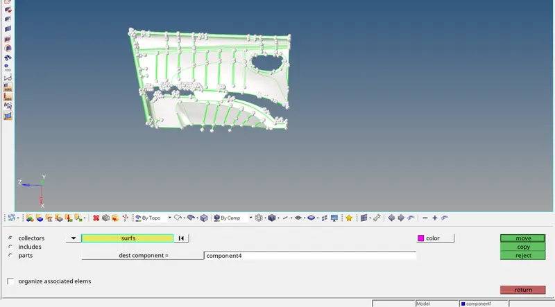
Now we can extract the midsurface of the splitted components one by one manually. But before that we should know how to properly check the thickness of the given geometry since it is not a regular
component with flat surface. To check the thickness of the given component, first create a node on the surface of the component whose thickness is to be found.
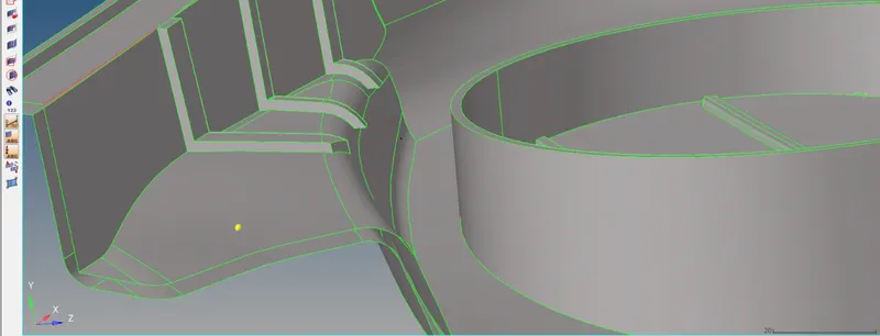
Now project the duplicate of this node on the surface on the opposite side. For that, go to Tool > Project > to surface. Set the entity selector to nodes. Select the created node. Right click on the entity
selector and click on duplicate. A duplicate of this node is now created. Now in the surface entity selector, slect the surface on the opposite side. Set the projection type to along normal. Click on project.
The duplicated node is now projected on the surface on the opposite side. Now we can easily measure the distance between these nodes to find out the thickness of the component.
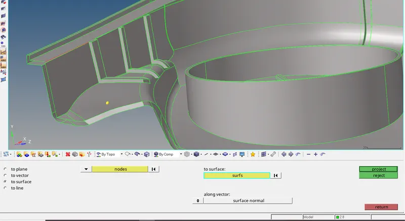
To measure the distance, press F4 from the keyboard to go to distance panel. Select the two nodes option. In the N1, N2 selector, Select the two nodes that we created.
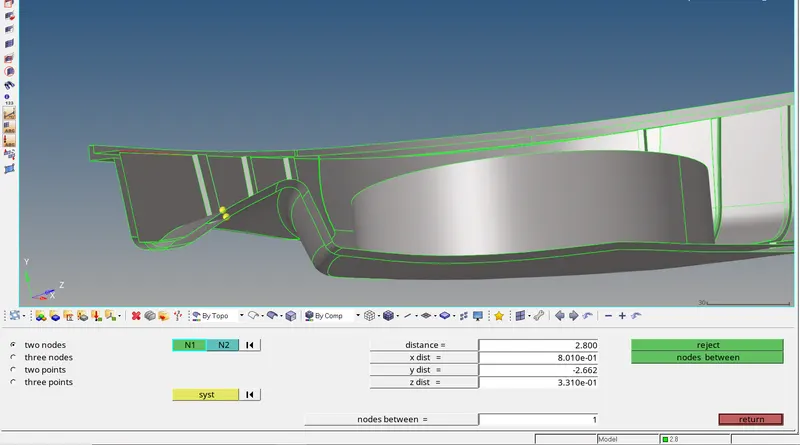
The distance shown is 2.8 units which is nothing but the thickness of the component. Now we can extract the mid surface of the component. Create a new component for the midsurface and make it current
component. Go to Geom > Surface edit > offset. Select the surface to be offset and enter the offset distance. Click on the surf entity selector and click on duplicate > current component. Click on offset. The
surface will be now offset by given distance.
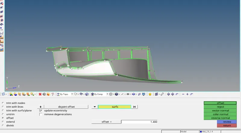
Use same procedure for the extraction of midsurface of the remaining geometry. For the ribs, we can defeature them by removing the present fillets and then extract the midsurface. Go to Geom > defeature
> surface fillet > find fillet in selected. Enter min radius as 0.5. Now select the rib and click on find.The fillet will be indentified. Now click on remove. The filled will be now removed.
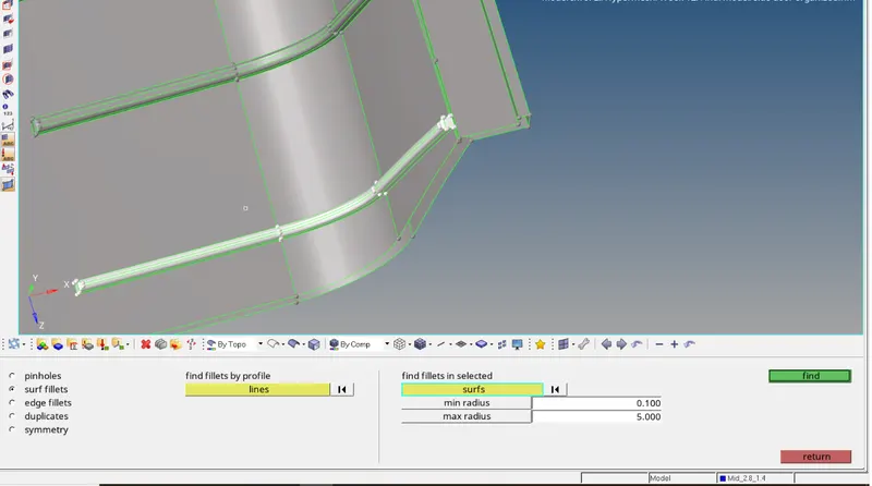
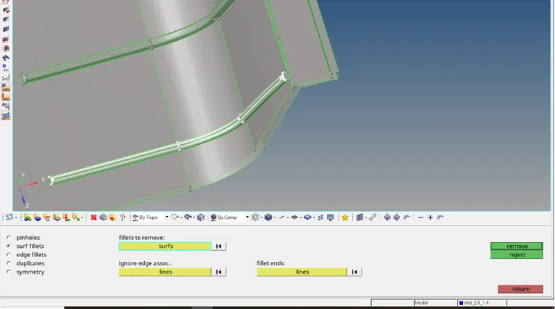
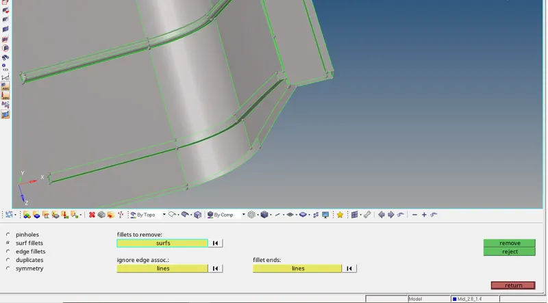
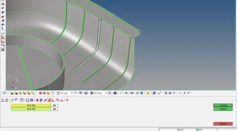
Now we can measure the thickness of the rib and extract the midsurface. To extract mid surface of rib with variable thickness, extract the midline of the rib first. Go to Geom > lines >midline. In the line list 1
& 2 select the displayed edge of the ribs as shown below and click on create. A midline is now created between these 2 lines.
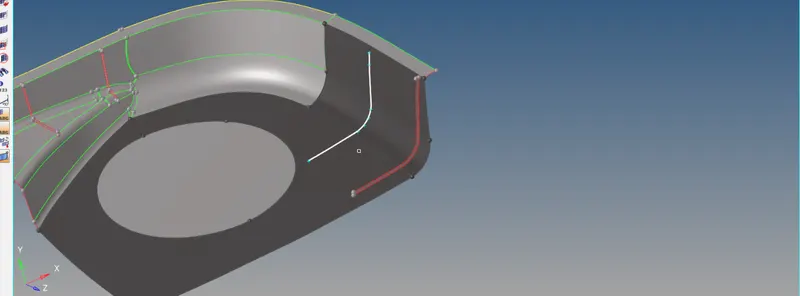
Now split the base surface with this line. Go to Geom > surface edit > trim iwth lines > with free lines. In the surface entity selector, select the surface to be trimmed, i.e base surface and in the free lines
selector, select the newly created midline and then click on trim. the surface will be trimmed with this line as shown below.
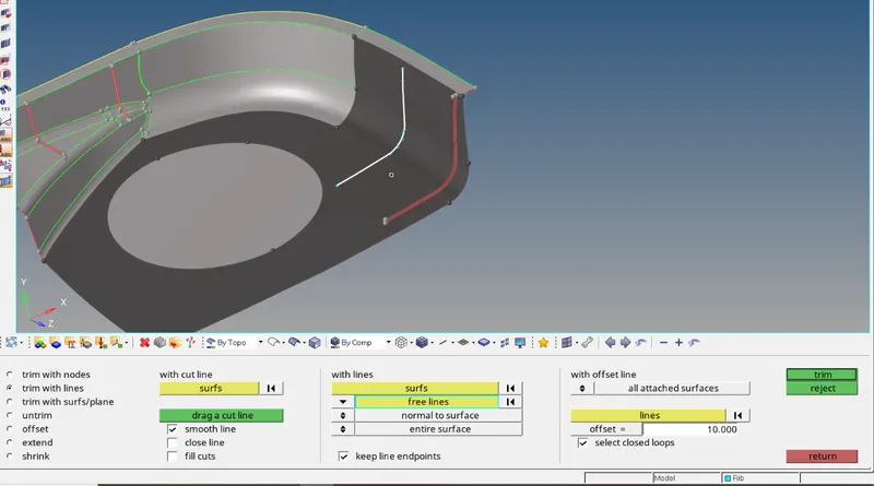
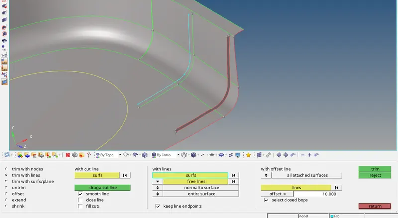
Now we can created surface between these two lines. Go to Geom >surfaces > ruled. In the list lists, select the midline and the split line which we just created and click on create. The surface will ne now
created as shown below.
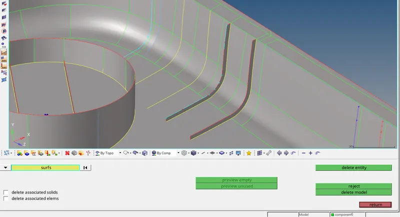
Thus, in this way the mid surface of the rib with variable thickness is created. Take thickness of such ribs as the average of max and min thickness of the rib. Now extract the mid surface of the
remaining parts to complete the midsurface of the geometry.
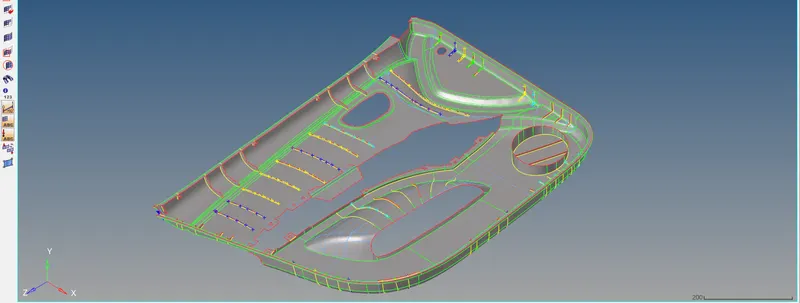
Now we can do geometry cleanup of the midsurface. Toggle unwanted split lines and split the geometry as per requirement.
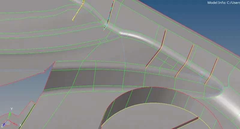
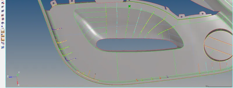
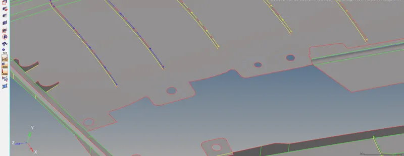
Now we can mesh the given component. Press F12 to go to automesh panel. Set the entity selector to Surface. Enter element size as 4 and mesh type as mixed. Click on align.Select the surface to be meshed
and click on mesh. The surface will be now meshed. Part by part mesh all the surfaces manually.
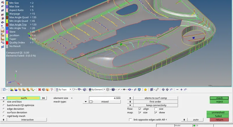
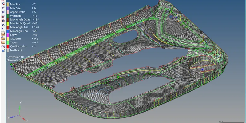
Now the entire FE model is completed. Now check for elements failing the quality criteria. Press F10 to go to check elements. Under 2D, enter the max values allowed for the given quality parameters and click
on the parameter name. The elements failing the quality parameter will be highlighted. Around 15 failing elements were found faling for lin length, max length, warpage and min int angle for quad. These were
easily fixed by smoothing the elements and adjusting the distance between nodes by using distance option available under Geom panel > Distance.
Check for any free edges between the elements to make sure all the nodes of the elements are connected. Go to Tool > edges. Set the entity selector to elements.
Click on the entity selector box and click on displayed. All the displayed elements will be selected. Click on find. The free edges will be extracted. Only the outer boundary should have free edges.
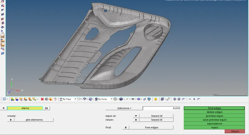
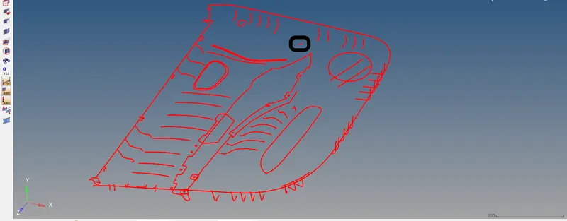
Few free edges were found as seen above. These were easily fixed by using equivalence option.
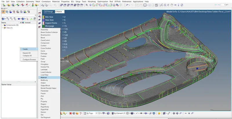
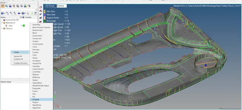
Now create property for the elements to assign them thickness. First let us create material. Right click on the model view > create > material. Rename it to steel.
Enter the default value of E, NU and RHO. The material is now created.
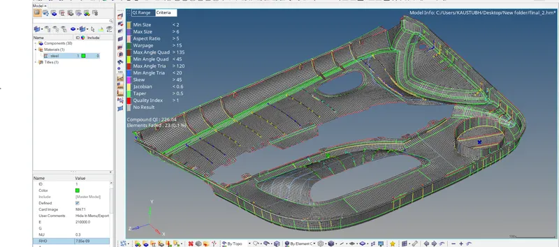
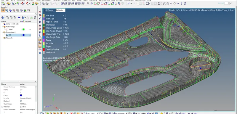
Again right click on the model view > create > property. Let's say we are creating property for elements having 2.8 thickness. So rename the created property to 2.8, so we can identify the property while
applying it to the component containing the 2.8 thickness element. Click on it and enter T = 2.8 and material as steel. The property card is now created.
Now assign this property card to the component having 2.8 mm thickness. Click on the component name in the model view under component collector. Click on property tab and select the property named
2.8. The property and material is now applied to this component.
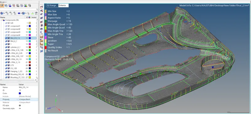
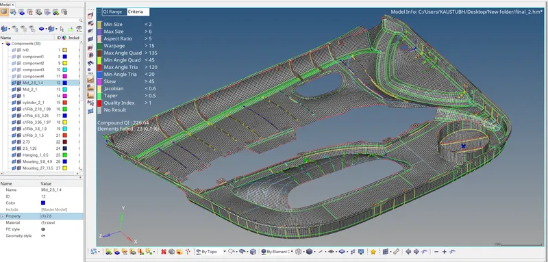
Similarly, create property for the remaining components and apply them to the components after creating them. There is now only one important check remaining now, the direction check of the normal of
the elements. Go to Tool > normals > element. Click on the entity selector box and select all. All the elements will be selected. click on Display. The direction of the normal will be indicated by color. Click on
adjust option to adjust the direction of normal if needed.
- Conclusion:
We have learnt to create midsurface manually for a complex plastic component with variable thickness and create 2D mesh on it. All the elements created pass the quality check parameter. Also while
working on the given geometry, we have learned how to repair distored surface by trimming only particular portion of the surface and creating a new surface at that portion. Also the use of midline
option for creating midline of the rib and using it to split the surface and create midsurface from it was learned.