Week 5 To analyze the simulation of bending of iPhone for the given material and find the directional deformation, life and safety factor in ANSYS.
OBJECTIVE:- To analyze the simulation of bending of iPhone for the given material and find the directional deformation, life and safety factor in ANSYS.
Case 1: Simulate the model as it is given in the video
PROCEDURE:-
- Open Ansys Workbench and choose static structural.
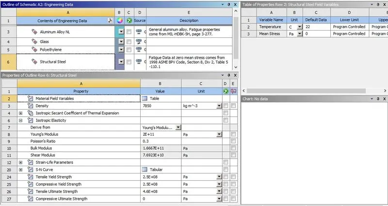
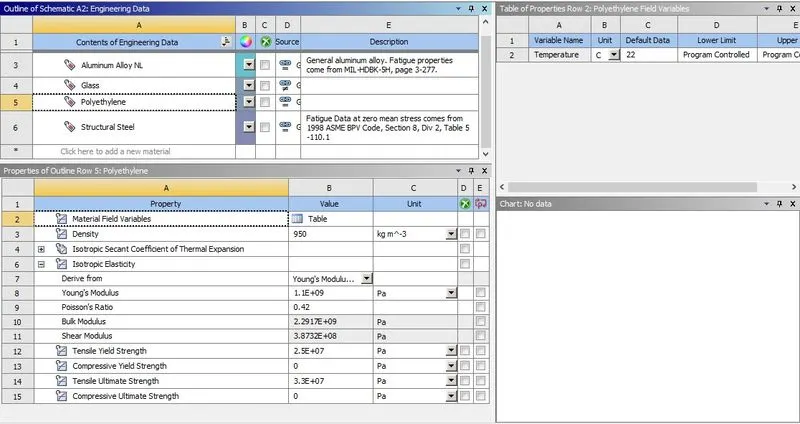
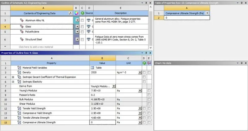
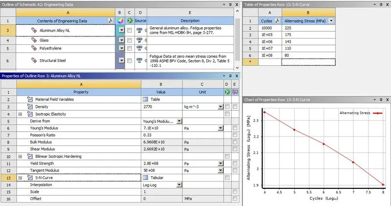
- In the Engineering data, let the material be structural steel and also choose Polyethylene from general materials and Aluminium Alloy NL from general non-linear material with default values. Now in the engineering data duplicate the Polyethylene and rename to Glass and provide below given values and in Aluminium Alloy NL add S-N curve whose tabular data values are shown below for Cycles and Alternating Stress (MPa).
Structural Steel
Polyethylene
Glass
Aluminium Alloy NL
- For the geometry, right-click and import the given "Iphone_Bending.x_t" and open with space claim.
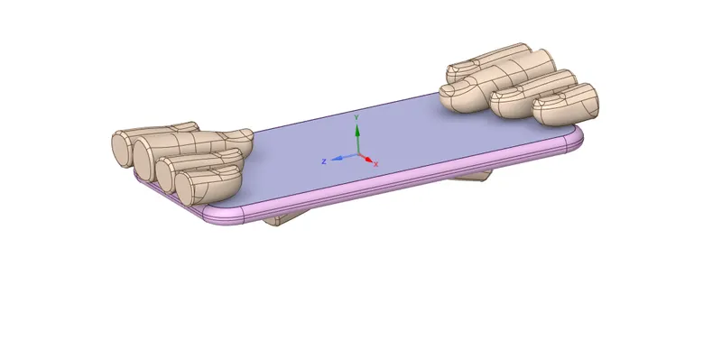
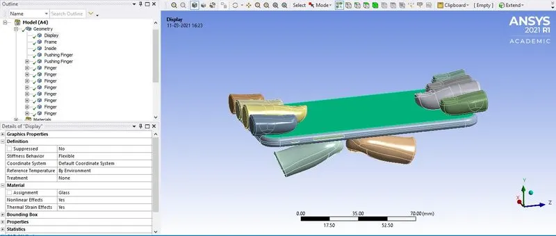
- Now in the workbench goto Model -> Edit, in the model window check the Geometry for the material and assign Structural Steel to all the fingers, Glass to the display, Aluminium Alloy NL to the frame and Polyethylene to the inside component.
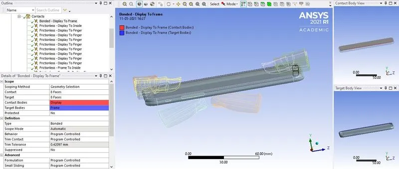
- For contact, delete any unwanted contacts and rename the rest of contacts based on definition, the display to frame contact should be type= bonded while all other contact type= frictionless.
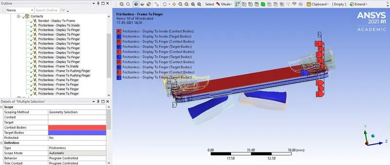
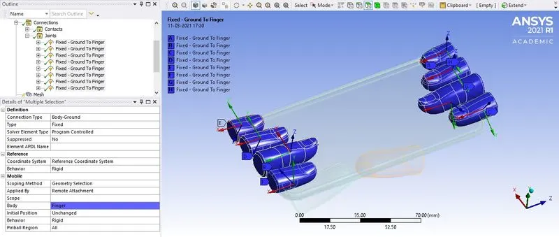
- Create individual joints with connection type= body-ground, type= fixed for all the 8 fingers present on the top.
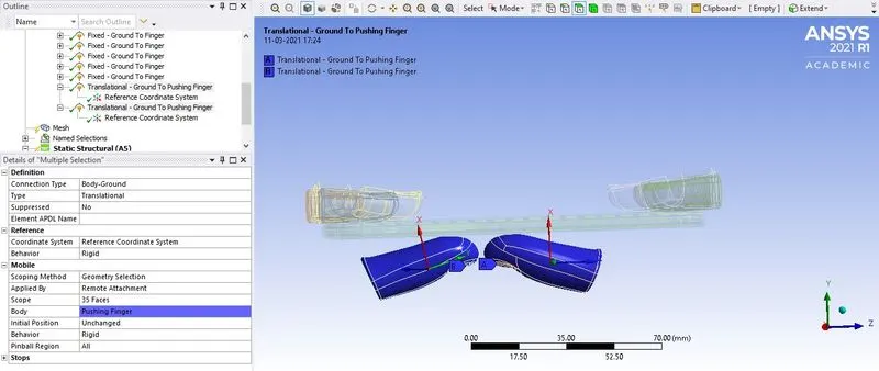
- For the bottom 2 pushing fingers, create individual joints with connection type= body-ground, type= translational and make sure the X-axis is pointing upward which can be changed by the reference coordinate system.
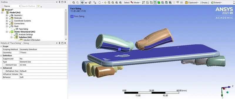
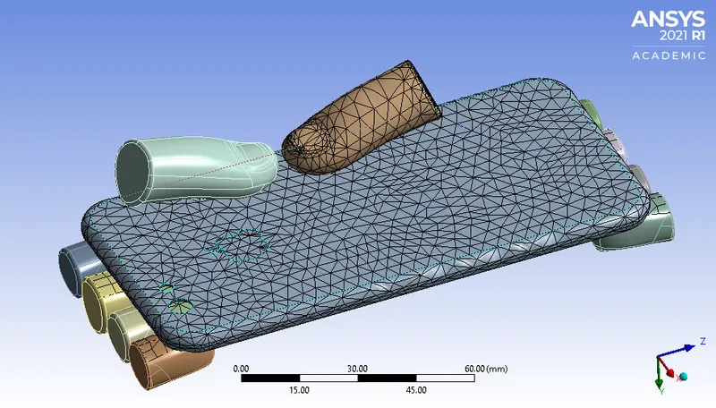
- For mesh, apply face sizing to the pushing finger and bottom of the frame with element size= 4mm and set the mesh quality smoothing to low and generate mesh.
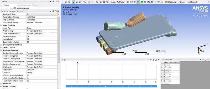
- For the analysis setting, the number of steps will be 8, select all the steps and choose solver type= direct, weak spring= programme controlled, large deflection= on, stabilization= constant, method= energy, energy dissipation ratio= 0.1, Activation for first substep= yes, in output control turn all to yes.
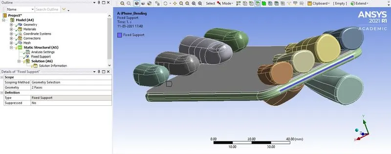
- Apply fixed support and select the 2 opposite faces present along the Z-axis of the inner component.
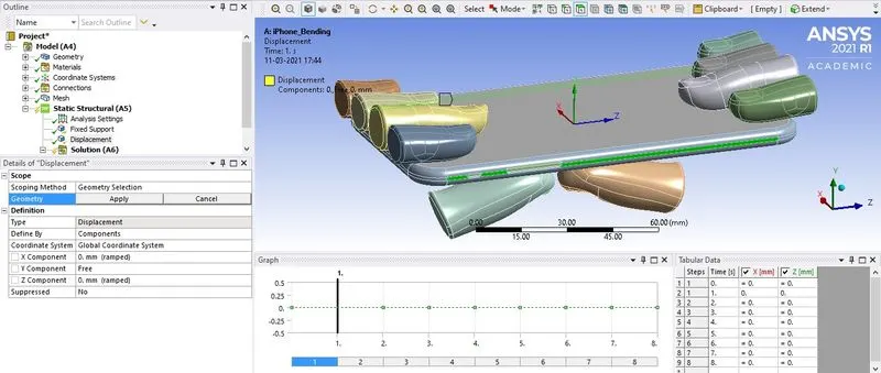
Apply displacement ad select the side faces of the frame present on the X-axis and select the X and Z component to be constant.
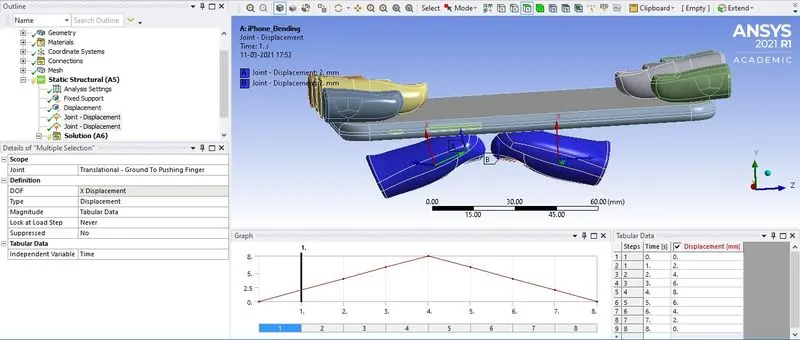
- Now apply joint load and select the translational joint individually of type= displacement and magnitude= tabular data, provide the displacement data.
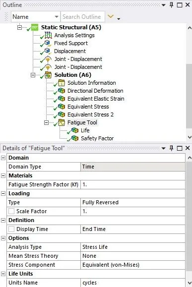
- In the solution request select for the required output like directional deformation along the y-axis, Equivalent elastic strain of the frame, Equivalent Stress on the frame, Equivalent Stress on the whole body, under fatigue tool- life and safety factor. Click on solve to generate the result.
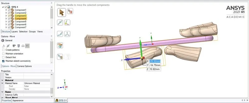
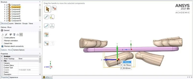
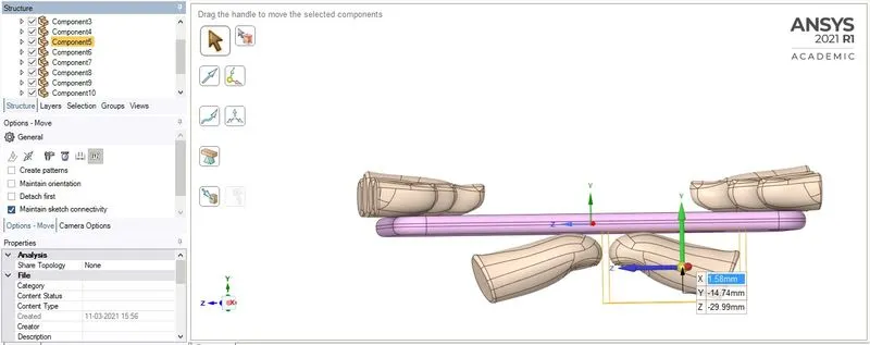
Case 2: Move the bottom fingers from their defined position to the given position X= 22.5mm & Z= 10mm and obtain the results for the simulation. Also define the S-N curve for the Aluminium Alloy material as per values given below and determine the fatigue life results for the same.
PROCEDURE:-
- All of the above settings are kept similar to Case 1, except only in the SpaceClaim the 2 pushing finger are moved to position X= 22.5mm & Z= 10mm which can be done with the help of Sketch -> Edit -> Move and select coordinates.
RESULT:-
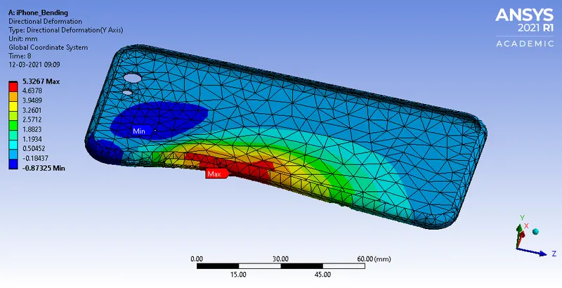
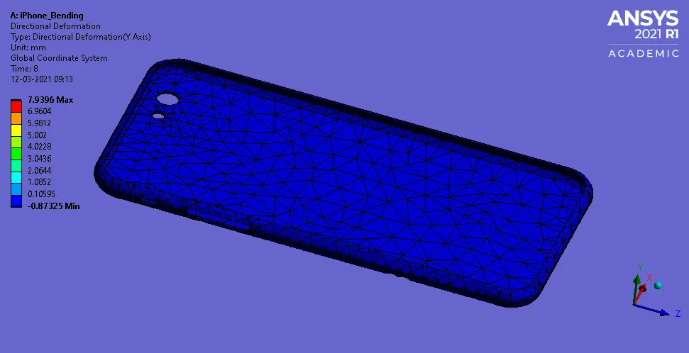
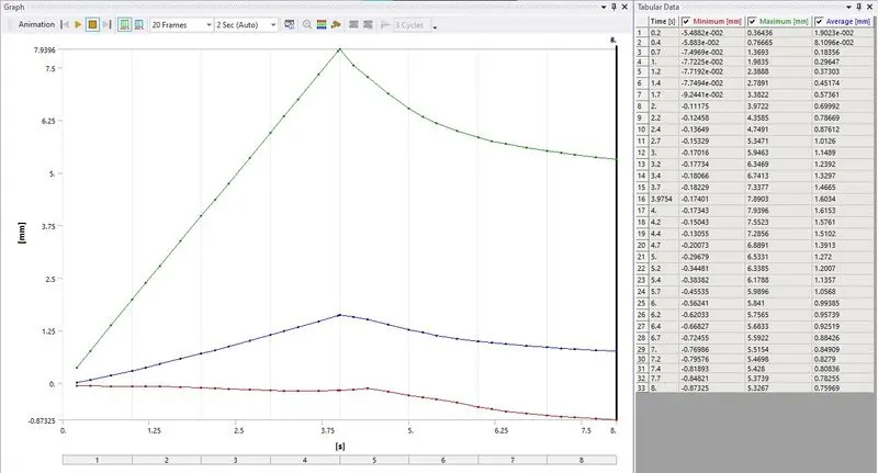
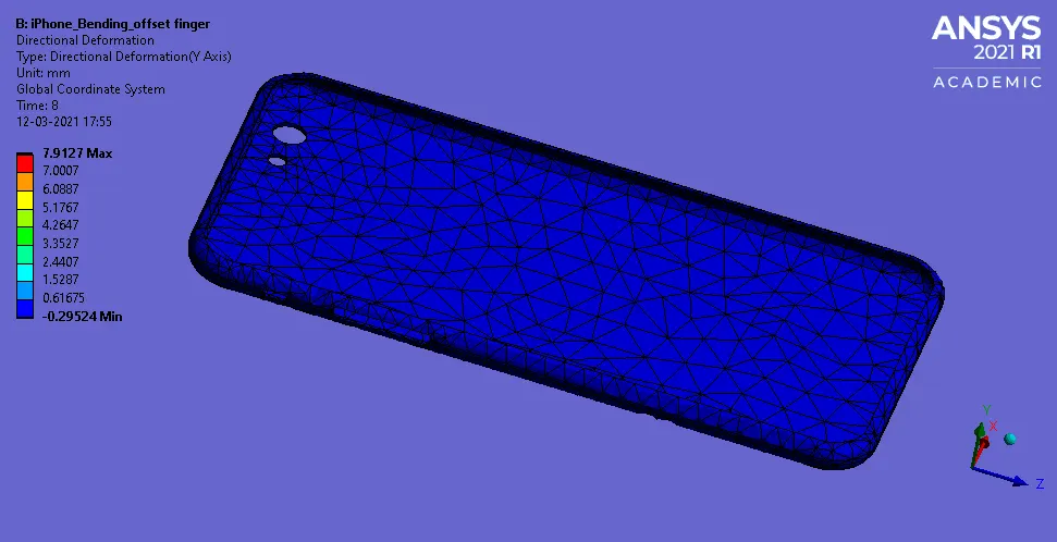
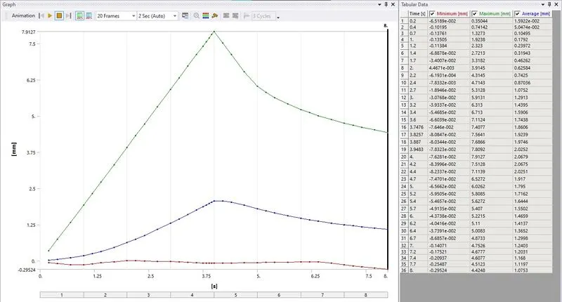
Directional Deformation Along Y-axis
CASE 1
CASE 2
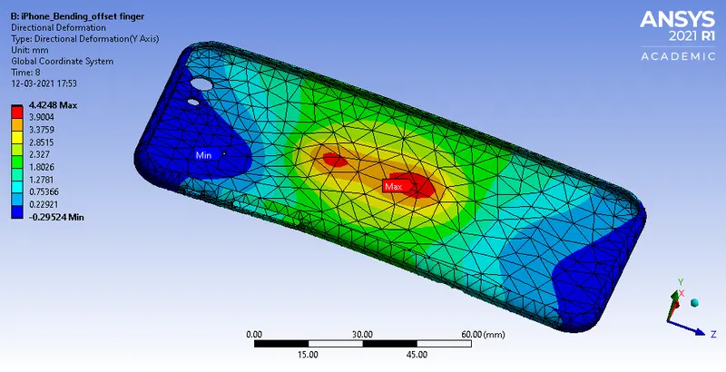
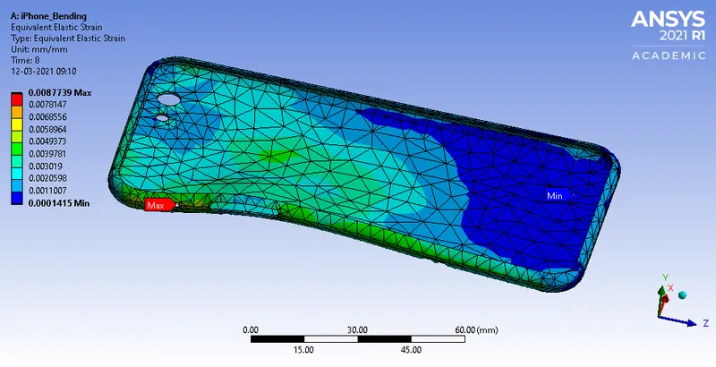
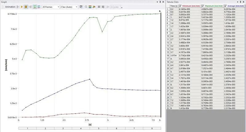
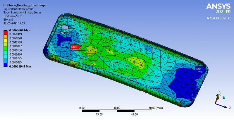
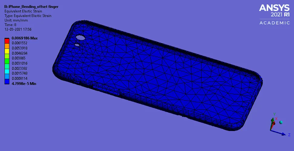
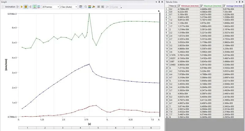
Equivalent Elastic Strain on Frame
CASE 1
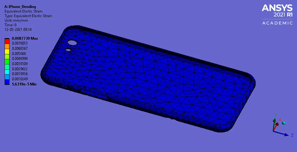
CASE 2
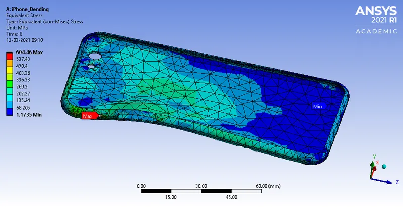
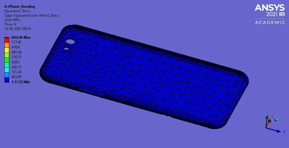
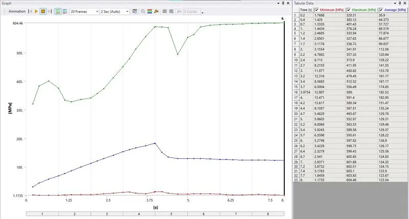
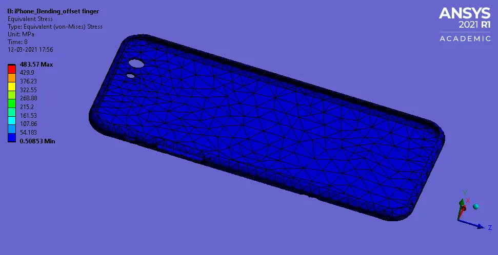
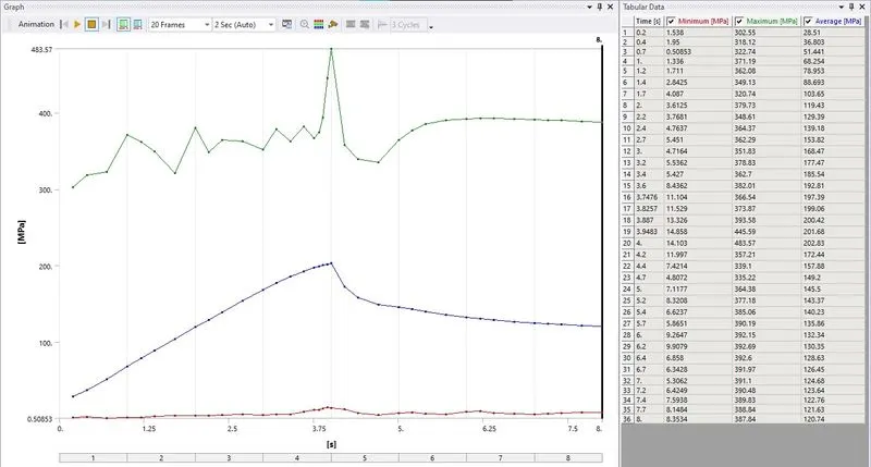
Equivalent Stress on Frame
CASE 1
CASE 2
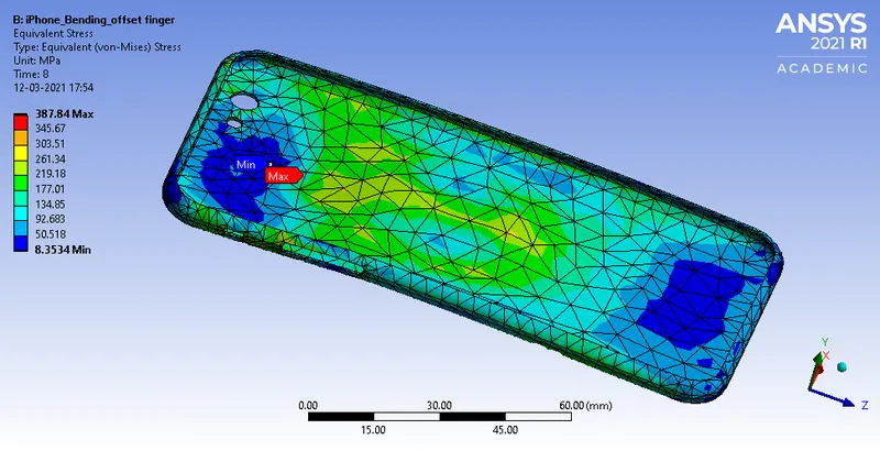
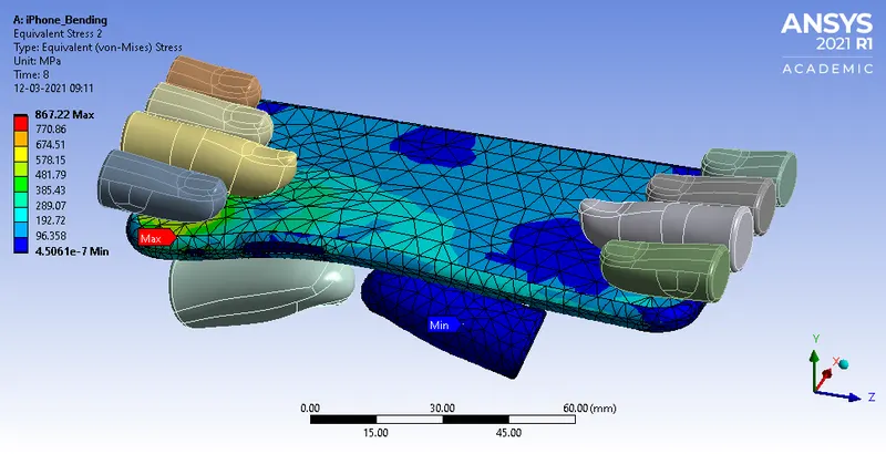
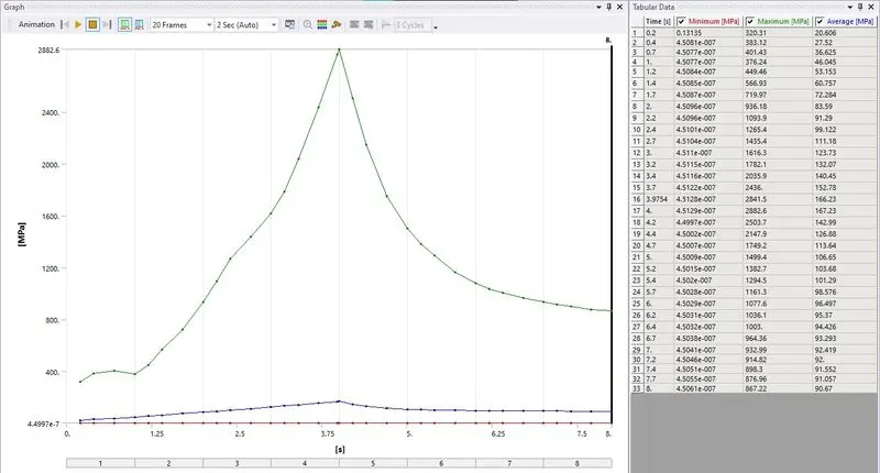
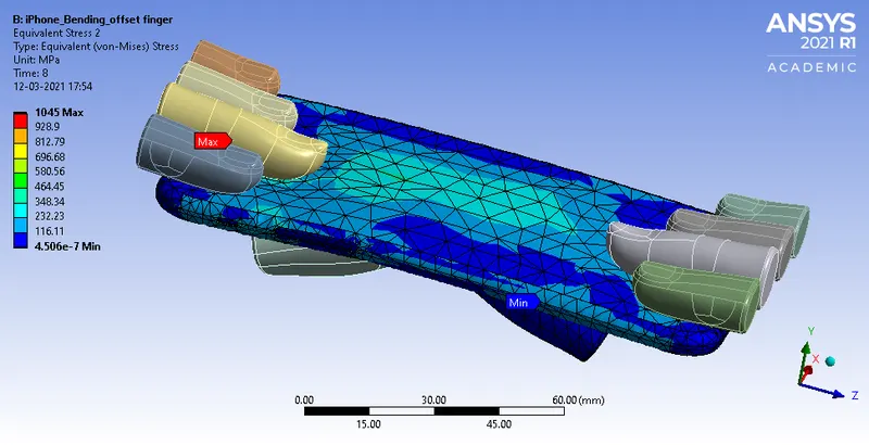
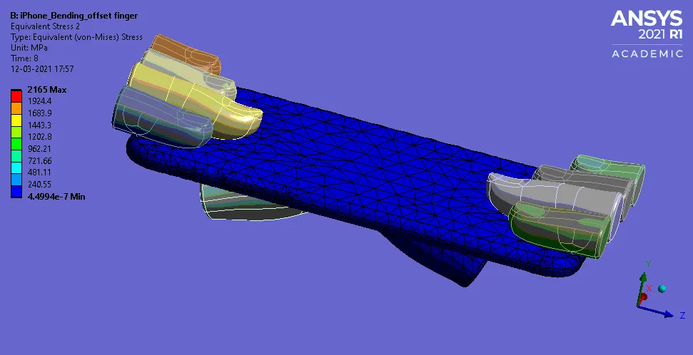
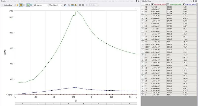
Equivalent Stress on Whole Body
CASE 1
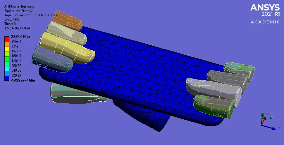
CASE 2
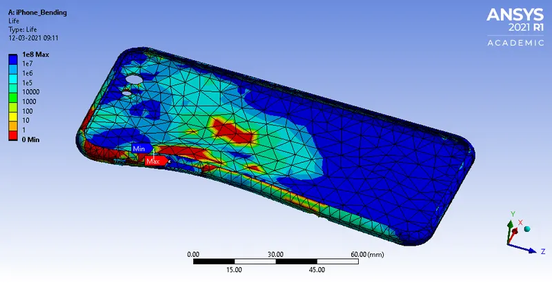
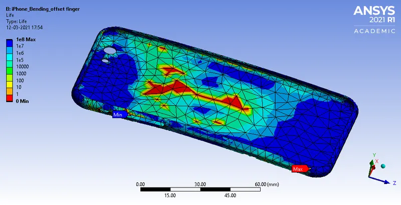
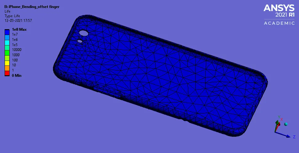
Life of Frame
CASE 1
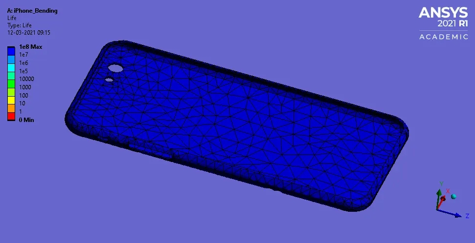
CASE 2
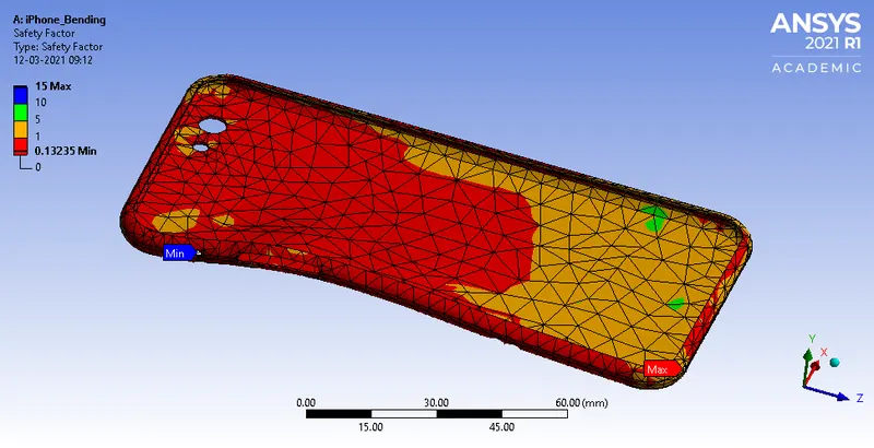
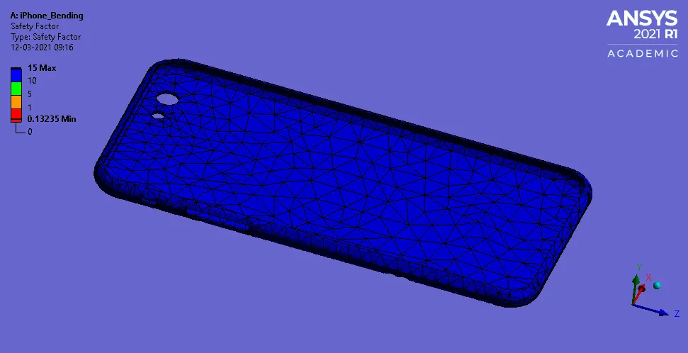
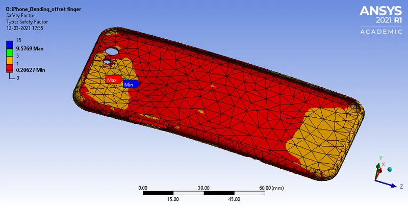
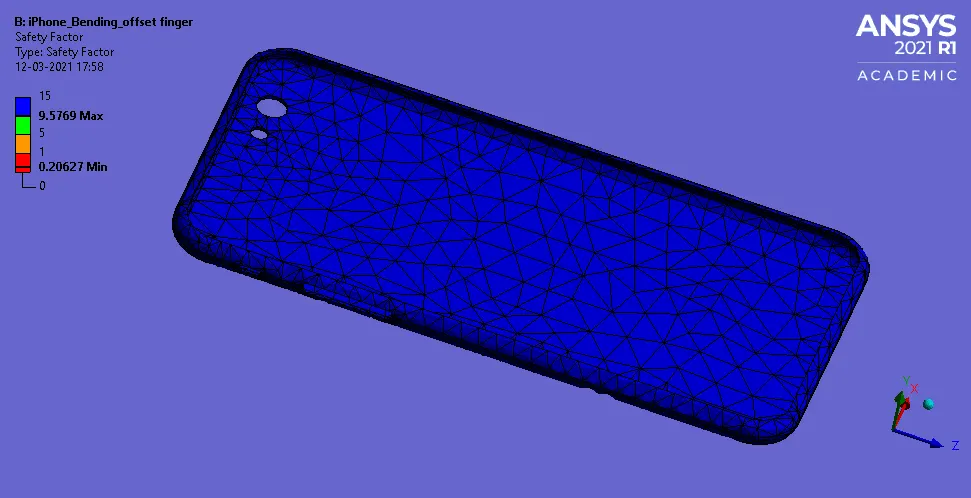
Factor Of Safety of Frame
CASE 1
CASE 2
| Directional Deformation Along Y-axis (mm) | Equivalent Elastic Strain of Frame (mm/mm) | Equivalent Stress on Frame (MPa) | Equivalent Stress on Whole Body (MPa) | Life (Cycles) | Factor of Safety | |||||||||
| Min. | Max. | Average | Min. | Max. | Average | Min. | Max. | Average | Min. | Max. | Average | Minimum | Minimum | |
| CASE 1 | -0.87325 | 5.3267 | 0.75969 | 1.42E-04 | 8.77E-03 | 2.32E-03 | 1.1735 | 604.46 | 123.54 | 4.51E-07 | 867.2 | 90.67 | 0 | 0.13235 |
| CASE 2 | -0.29524 | 4.4248 | 1.0753 | 3.39E-04 | 6.36E-03 | 2.29E-03 | 8.3534 | 387.84 | 120.74 | 4.51E-07 | 1045 | 91.919 | 0 | 0.20627 |
It can be observed from the analysis and table that Case 1 experience the highest max. directional deformation along the Y-axis of about 5.3267 mm, max. equivalent elastic strain on the frame of about 8.77E-03 mm/mm and max. equivalent stress on the frame of about 604.46 MPa while Case 2 experiences the highest max. equivalent stress on the whole body of about 1045 MPa because of offset of the fingers near to the middle but both the cases have life cycles of 0 because the highest stress given was 225 MPa for 10000 cycles but in both the cases the max. stress experienced is greater than 225 MPa, for the factor of safety the min. for case 1 is 0.13235 and for case 2 is 0.20627.
CONCLUSION:-
So from the analysis, it can be inferred that Case 1 experience the highest max. directional deformation along the y-axis and the life cycle for both the cases is obtained 0 as both cases experiences stress greater than the stress provided in the S-N curve table and the factor of safety obtained is min. for case 1 is 0.13235 and for case 2 is 0.20627.
Simulation File- "https://drive.google.com/file/d/1X698Xgnbqg6Gh-seCOkrEyygPIAxeqkk/view?usp=sharing"