Simulation of Battery characteristics using drive cycle
Aim:- Simulate generic battery model charge discharge using UDDS data.
Ans:-
A driving cycle is a series of data points representing the speed of a vehicle versus time. Driving cycles are produced by different countries and organizations to assess the performance of vehicles in various ways, as for instance fuel consumption, electric vehicle autonomy and polluting emissions
Another use for driving cycles is in vehicle simulations. More specifically, they are used in propulsion system simulations to predict performance of internal combustion engines, transmissions, electric drive systems, batteries, fuel cell systems, and similar components.
UDDS CYCLE:-
The EPA Urban Dynamometer Driving Schedule (UDDS) is commonly called the "LA4" or "the city test" and represents city driving conditions. It is used for light duty vehicle testing. The UN/ECE Regulation 53 refers to the EPA UDDS as the "Test Equivalent to the Type 1 Test (verifying emissions after a cold start)."
Referance Sheet for UDDS Cycle:- https://drive.google.com/file/d/1LzZDUZNeQCceivsBbQ2_O7OnHVK6yFcz/view?usp=sharing
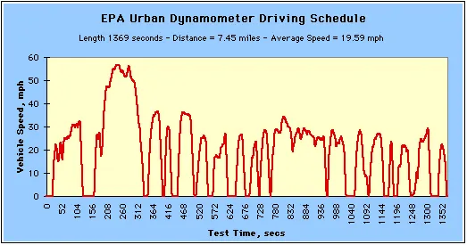
Battery Charging According with UDDS cycle:-
The charging and discharge of battery requires the current/ charge graph, because battery will not understand the speed Vs Time graph. Hence we convert this UDDS cycle chart to equivalent current chart as below.
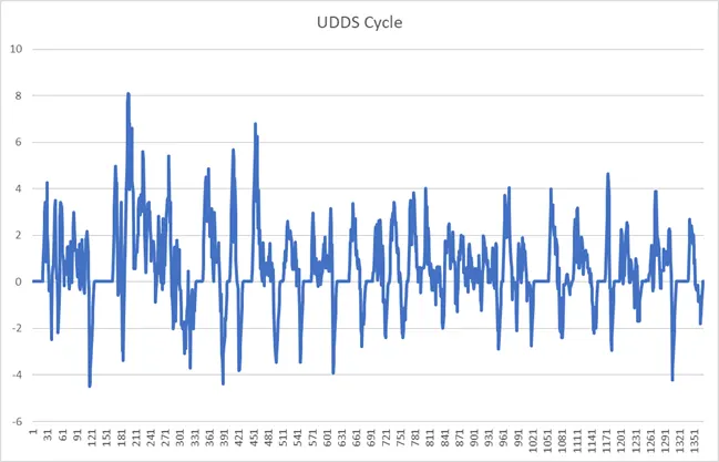
According with the above cycle we build generic battery model:-
Simulink Model:-
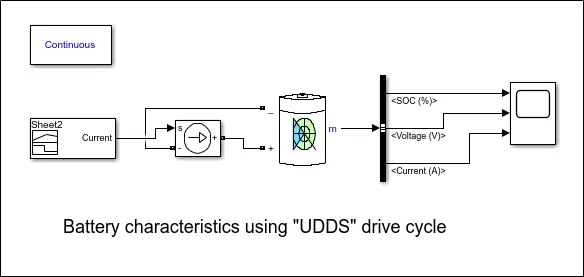
In this model we use following component: -
- Signal builder: - by using this block we give UDDS cycle current as input. For this we import the UDDS cycle data to signal builder block.
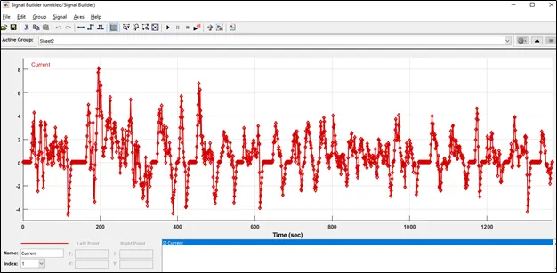
On Y axis there is current drawn or deliver by battery, and on X axis time is shown.
- Controlled Current Source:-
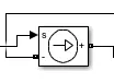
The Controlled Current Source block converts the Simulink input signal into an equivalent current source. The generated current is driven by the input signal of the block. The positive current direction is as shown by the arrow in the block icon.
This is controlled current source, which deliver or draw the current from battery as per the UDDS cycle.
- Generic Battery Model:-

The Battery block implements a generic dynamic model that represents most popular types of rechargeable batteries. The circuit parameters are shown in below:-
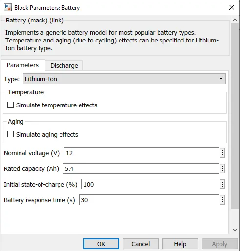
Here we are using Lithium Ion battery which are normally used for Automobile application with 12 V nominal voltage & 5.4 Ah rated capacity.
- Measurement:- For the Measurement of battery parameters, we use battery “M” port, which is connected to Bus selector, it will basically separate the parameters like SOC, voltage & current in separate BUS. Then we use Scope to visualize the result
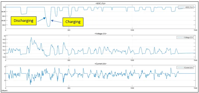
This is graph for battery parameters, we can see the battery SOC is becoming up & down according with charging & Discharging of battery.
The negative current displays current coming into the battery means charging, and positive current shows discharging of battery.
- Nikita Solankican you please provide me this current profile data. also can you please explain how you converted speed vs time data into current vs time data?