Thermal Management of Electric Vehicle Battery pack
1. Aim:-
Prepare a report summarizing thermal management techniques for electric car battery pack.
2. Introduction:-
Electric vehicle and hybrid electric vehicle (EV/HEV) technology, as a green substitute for conventional combustion vehicles, has attracted a significant amount of attention globally and are quickly replacing internal combustion engine-powered vehicles.
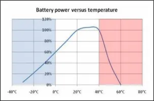
the performance of EVs and HEVs are highly dependent on battery capacity. Battery thermal management systems (BTMS’) are developed to monitor and optimize the thermal status of batteries. The battery temperature is a critical factor for battery operating performance. Specifically, the charge/discharge capacity can be strongly influenced by temperature. This availability will further impact the performance of applications. For instance, the discharge rate will determine the acceleration process of electric and hybrid electric vehicles. The lifespan of batteries also greatly depends on the operating temperature. Under normal operating conditions, of say −30 °C to 60 °C, the battery health varies significantly from the optimal battery temperature range.
Efficient temperature management systems contribute significantly to battery health and extend the overall lifespan. Moreover, as the capacity and charge/discharge rate increase, battery security issues need more attention. Subsequently, various BTMS’ has been developed to meet the demand for higher power, faster charge rates, and improved driving performance. Modern BTMS’ are divided into two groups: active systems and passive systems . Passive BTMS generally employ phase change materials, heat pipes, and hydrogels. Zero extra power consumption is the most prominent feature of these systems. However, the cooling process is difficult to manage. Conversely, traditional active methods generally lead to forced circulation and circulation of specific cooling materials and substances such as water and air. The main issue is that the cooling effect can be very limited under certain circumstances. Thermoelectric power generation devices for vehicles have been developed for years. In contrast, thermoelectric coolers (TEC) which employed by battery thermal management are a comparatively new candidate for electric vehicles. These benefit from strong cooling capacities and reliable working potential, and have attracted increasingly more attention for integration into BTMS.
The battery thermal management system (BTMS) plays a vital role in the control of the battery thermal behaviour. The BTMS technologies are: air cooling system, liquid cooling system, direct refrigerant cooling system, phase change material (PCM) cooling system, and thermo-electric cooling system as well as heating. These systems are analysed through a trade-off between performance, weight, size, cost, reliability, safety and energy consumption. According to the analysis two prime battery thermal management systems are recommended: combined liquid system (CLS) and a variant system with PCM.
- THEORY:-
In this report we are mainly looking forward to study the lithium iron battery.
2.1) Working of Lithium Iron Battery:-
A lithium-ion battery consists of an anode, cathode and electrolyte as well as a separator,The anode, is the oxidised electrode which removes electrons to the external circuit during discharging. Correspondingly, the cathode, is the oxidising electrode which receives electrons from the external circuit. The electrolyte is the medium to transfer ions between electrodes inside the cell and the separator is used to isolate electrodes. Also, the solid electrolyte interface (SEI) is thin passivation layer which is formed on the surface of the carbon anode during the first charge. It slows down the reaction rate and decreases the current.
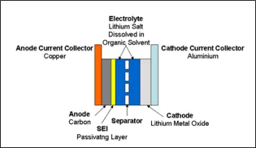
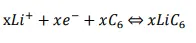
Li-ion battery is rechargeable which means we can recharge the battery. Lithium ions disperse from the negative to the positive when discharging and go in reverse when charging. Lithium-ion battery use intercalated lithium compound as the electrode instead of metallic lithium. The electrochemical reactions for Li-cobalt in the positive electrode and negative electrode are expressed as following:
The Anode reaction is:

Cathode Reaction:-
There are several types of lithum iron batteries depending on which type of material is used as cathode.
Following table shows the comparison between these six types of Batteries: -
|
LCO- Lithium Cobalt Oxide |
LMO- Lithium Manganese Oxide |
NCA- Lithium Nickel Cobalt Aluminum Oxide |
LFP- Lithium Iron Phosphate |
LTO- Lithium Titanate (Li2TiO3) |
NMC- Lithium Nickel Manganese Cobalt Oxide |
|
|
Anode |
Graphite |
Graphite |
Graphite |
Graphite |
Lithium titanate |
Graphite |
|
Cathode |
cobalt oxide |
lithium manganese oxide |
Lithium Nickel Cobalt Aluminum Oxide (LiNiCoAlO2) |
Lithium Iron Phosphate (LiFePO4) |
lithium manganese oxide |
Lithium Nickel Manganese Cobalt Oxide(LiNiMnCoO2) |
|
Anode Reaction |
C6Li → 6C + Li+ + e− |
Li → Li+ + e− |
C6Li → 6C + Li+ + e− |
LixCn → nC + xLi+ + xe− |
Li7Ti5O12 → Li4Ti5O12 + 3Li+ + 3e− |
LixCn → nC + xLi+ + xe− |
|
Cathode Reaction |
Li1−xCoO2 + xLi+ + xe− → LiCoO2 |
MnO2 + Li+ + e− → LiMnO2 |
NiCoAlO2 + Li+ + e− → LiNiCoAlO2 |
LiMnO2 + Li+ + e− → LiMnO2 |
3MnO2 + 3Li+ + 3e− → 3LiMnO2 |
Li1−x(Ni1−x−yMnxCoy)O2 + xLi+ + xe− → LiNiMnCoO2 |
|
Overall Reaction |
C6 + LiCoO2 ↔ LixC6 + Li1−xCoO2 |
Li + MnO2 ↔ LiMnO2 |
C6Li + NiCoAlO2 ↔ Li1−xNiCoAlO2 + LixC6 |
Cn + LiFePo4 ↔ FePo4 + LiCn |
Li7Ti5O12 + 3MnO2 ↔ Li4Ti5O12 + 3LiMnO2 |
LixCn + Li1−x(Ni1−x−yMnxCoy)O2 ↔ LiNiMnCoO2 + nC |
|
Voltage Range |
3.60V nominal |
3.70V (3.80V) nominal |
3.60V nominal |
3.20, 3.30V nominal; |
2.40V nominal; |
3.70V (3.80V) nominal |
|
Specific energy (capacity) |
150–200Wh/kg |
100–150Wh/kg |
200-260Wh/kg |
90–120Wh/kg |
50–80Wh/kg |
150–200Wh/kg |
|
Thermal runaway |
150°C (302°F) |
250°C (482°F) |
150°C (302°F) |
270°C (518°F) |
Very high |
210°C (410°F) |
|
Application |
Mobile phones, tablets, laptops, cameras |
Power tools, medical devices, electric powertrains |
Medical devices, industrial, electric powertrain (Tesla) |
Portable and stationary needing high load currents and endurance |
UPS, electric powertrain (Mitsubishi i-MiEV, Honda Fit EV), solar-powered street lighting |
E-bikes, medical devices, EVs, industrial |
2.2) Thermal Issues with Lithium Iron Battery:-
Lithium-ion cells performance depends on both the temperature and the operating voltage. Lithium-Ion cells work well when cells operate within limited voltage and temperature. Otherwise, damage will occur to the cells and will be irreversible. In over-voltage situations the charging voltage exceeds the bearable cell voltage, resulting in excessive current flows and at the same time, it causes two problems. At excessive currents the Lithium-ions are deposited more rapidly than intercalation to the anode layers, Lithium ions are then deposited on the surface of the anode as metallic Lithium. This is Lithium plating. It gives rise to the reduction in the free Lithium ions and an irreversible capacity loss.
There are two types of metal lithium plating, namely homogeneous lithium plating and heterogeneous lithium plating, but the lithium plating is dendritic in form. Eventually it can result in a short-circuit between the electrodes.
As with over-voltage, under-voltage also brings about problems which give rise to the breakdown of the electrode materials.
Chemical reaction rates have a linear relation to temperature. The decrease of the operating temperature will reduce reaction rate and the capacity of carrying current during charging or discharging. In other words, the battery power capacity is decreased. Moreover, the reduction of reaction rate makes it harder to insert lithium ions into intercalation spaces. The result is the reduction of power and lithium plating causing the capacity loss.
High temperature increases the reaction rate with higher power output, however, it also increases the heat dissipation and generates even higher temperatures. Unless heat is dissipated quicker than heat is generated, the temperature will be higher and finally a thermal runaway will result.
Thermal runaway consists of several stages and each stage will give rise to more irreversible damage to cells. First, the SEI layer is dissolved to electrolyte at round 80ºC. The primary overheating may result from excessive current or high ambient temperature. After breakdown of the SEI layer, electrolyte begins to react with the anode. This reaction is exo-thermal which drives the temperature higher. Secondly, the higher temperature causes the organic solvents to break down with the release of hydrocarbon gases. Normally this starts at around 110 ºC. The pressure inside cells is built up by the gas and the temperature is beyond the flashpoint. However, the gas does not burn due to the lack of oxygen. A vent is needed to release the gas in order to keep cells under proper pressure and avoid a possible rupture. Then, the separator is melted and short-circuits occur between the anode and cathode at 135 ºC. Finally, the metal oxide cathode breaks down at 200 ºC and releases oxygen which allows the electrolyte and hydrogen gas to burn. This reaction is also exo-thermal and drives temperature and pressure still further.
2.3) Battery Thermal Management System (BTMS)
As we see in section 2.2, there are many possible safety and operating condern which limit the operation of battery, if the battery temperature exceeds the particular value. For this we should have a proper Thermal management systems installed with the battery, which not only keep battery temperature below the safety condition but also increase the life of battery.
The BTMS should have following essential function:-
- Cooling:- Due to inefficiency, battery cells will not only generate electricity but also heat. This heat should be moved from the battery pack when battery temperature reaches the optimum temperature or even in advance. Thus, a cooling function is required in BTMS
- Heating:- In cold climates, battery pack temperature probably falls below the lower temperature limit. Hence, a heating function, such as PTC heater, is required to assist the battery pack to reach the proper temperature range in a shorter time.
- Insulation:- In extreme cold or hot weather, the temperature difference between the inside and outside of the battery pack is much larger than that in mild weather. Battery temperature will thus fall (cold) or rise (hot) sooner out of the proper temperature range. To prevent this, good insulation can slow down the falling or rising of battery temperature, especially when the vehicle is parked outdoors.
- Ventilation:- Ventilation is required to exhaust the hazardous gases within battery pack. In some systems, such as air systems, this function is combined with cooling and heating functions.
Types of BTMS system:-
Fundamentally there are two type of Cooling:-
Passive cooling:- Passive cooling utilizes natural conduction, convection, and radiation to cool a component.
Active cooling:- Active cooling requires the use of energy specifically dedicated to cooling the component.
On the basis of which type of material used for cooling there are following types:-
- Air Cooling and Heating
Air systems use air as the thermal medium. The intake air could be direct either from atmosphere or from the cabin and could also be conditioned air after a heater or evaporator of an air conditioner. The former is called passive air system and the latter is active air system. Active systems can offer additional cooling or heating power. A passive system can offer some hundreds of watts cooling or heating power and an active system power is limited to 1 kW.
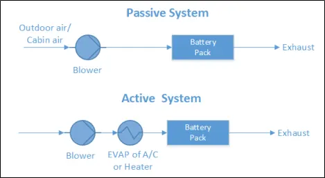
Because in both cases the air is supplied by a blower, they are also called forced air systems. Air system offers full functions of heating, cooling and ventilation. There is no need to build an additional ventilator, but it must be noted that the exhaust air cannot be returned to the cabin again. In some cases, a heat recovery unit (air-air heat exchanger) is mounted after the battery pack in order to recovery the heat from the exhaust air.
2. Liquid Cooling and Heatin
Besides air, liquid is another heat transfer fluid to transfer heat. There are generally two groups of liquids applied for thermal management systems. One is dielectric liquid (direct-contact liquid) which can contact the battery cells directly, such as mineral oil. The other is conducting liquid (indirect-contact liquid) which can only contact the battery cells indirectly, such as a mixture of ethylene glycol and water. Depending on the different liquids, different layouts are designed. For direct-contact liquid, the normal layout is to submerge modules in mineral oil. For indirect-contact liquid, a possible layout can be either a jacket around the battery module, discrete tubing around each module, placing the battery modules on cooling/heating plate or combining the battery module with cooling/heating fins and plates
By different heat-sinks for cooling, liquid systems can also be categorized into either passive systems or active systems. In passive liquid system, the heat-sink for cooling is a radiator. This system has no ability to heat.
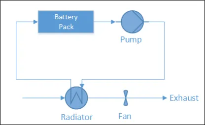
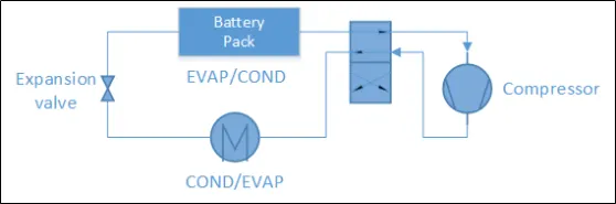
3. Direct Refrigerant Cooling and Heating
Similar to active liquid systems, a direct refrigerant system (DRS) consists of an A/C loop, but DRS uses refrigerant directly as heat transfer fluid circulating through battery pack.
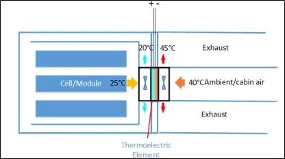
4. Thermo-electric Module
Thermo-electric module can convert electric voltage to temperature difference and viceversa. Here the former effect is adopted. That means it transfers heat through the module by consuming electricity directly. The schematic structure is presented in Figure 3.7. Two fans are installed to improve heat transfer by forced convection. To combine a passive air system with thermo-electric module, the combined system is able to cool down the battery even lower than the intake air temperature, but the power is still limited to around some hundreds of watts and less than one kW.
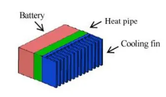
5. Heat Pipe:- Besides thermo-electric modules, a heat pipe is another way to upgrade passive air systems. The flat copper envelope of the heat pipe was under partial vacuum. The capillary structure is made of sintered copper powder. The heat pipe uses water as the working fluid. Water on the evaporator side will absorb heat and become vapour lower 100°C due to low pressure inside. Water on the condenser will dissipate heat to the surrounding and become liquid again. This cycle repeats again and again.
6. PTC Heater:-
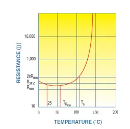
PTC thermistors have many self-heated applications by utilizing their own voltage current or current-time characteristics. One of the applications is as a self-regulating heater known as a PTC heater. The temperature of a PTC heater can be kept at a fixed point through adjusting the resistance of PTC heater automatically,
7. PCM Module:-
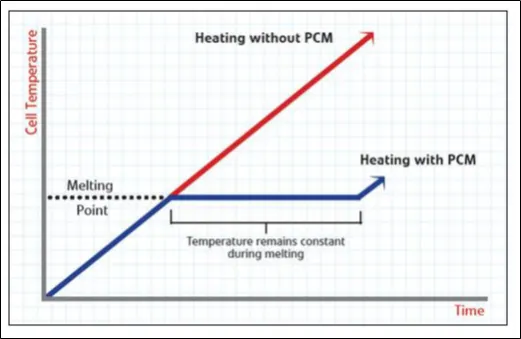
During melting, heat is absorbed by PCM and is stored as latent heat until the latent heat is up to the maximum. The temperature is kept at melting point for a period and the temperature increase is delayed. Therefore, PCM is used as conductor and buffer in battery thermal management systems.
A PCM is always combined with air cooling system or liquid cooling system to manage the battery temperature.
In this particular report we are not going into deep into modelling of Battery thermal modeling system, as this is overview:-
3.Result of BTMS:-
For analysis purpose we are considering following Simulink model of Battery thermal management system.(CLS model)
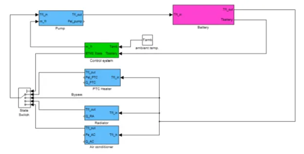
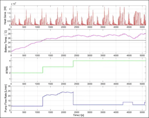
In the basic layout, the temperature flow of heat transfer fluid connects the main parts together. In initial step, testing data was loaded. Then starting with the battery unit the fluid was heated up. Afterwards, the fluid flows through different parts, but only one outcome was chosen by control unit. The flow rate of the pump was also governed by control unit. Lastly, the coolant returned to battery pack. This calculation process was repeated until the driving cycle ended. Here we are using NEDC driving cycle for evaluation .
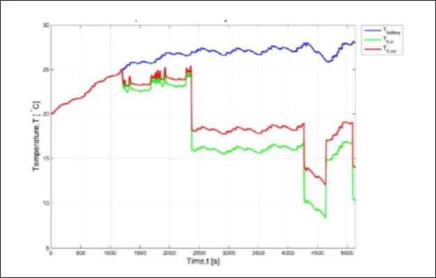
Below figure shows the temperature changes over time. Blue curve represents the battery temperature; green, the heat transfer fluid (coolant) inlet temperature before battery unit; and red, the coolant outlet temperature after battery unit.
Below figure gives an overview of the whole operation feature. It consists of information about heat generation rate, battery temperature, state of the BTMS and pump flow rate.
PCM Model:-
PCM(Phase change material) uses latent heat to reduce the energy consumption and delay the increase of temperature which was verified through the simulation.
The PCM model showed that the electric range of EV was sensitive to the vehicle mass. PCM could bring significant improvement of BTMS, but the mass of PCM was difficult to choose.
PCM cooling systems perform well on thermal management. Even under high ambient temperatures from 45°C to 50°C, the temperature inside the cell pack is always below 55°C because of high thermal conductivity and latent heat. The weakness of PCM is that it is more suitable for cold conditions or in space. When the temperature of the battery pack is higher than the temperature of the PCM melting CHALMERS, Applied Mechanics, Master’s Thesis 2014:42 21 point, heat is stored as latent heat and will be released to the module of battery when the ambient temperature is lower than the temperature of the PCM melting point.
4.Conclusion:-
CLS model indicate how the driving behaviour, battery initial temperature and ambient temperature influenced the BTMS and the corresponding electricity consumption. From the results it was seen that different driving cycles would change the BTMS feature significant in hot weather but less significantly in cold weather. The ambient temperature was the most important variable for the BTMS.
The PCM model have that the electric range of EV was sensitive to the vehicle mass. PCM could bring significant improvement of BTMS, but the mass of PCM was difficult to choose.
5.Referances:-
i) Battery Thermal Management Systems of Electric Vehicles by JILING LI & ZHEN ZHU (Chapter 2.1, 3.1, 5.1)
ii) “Electric Vehicle Battery Thermal Issues and Thermal Management Techniques” by John P. Rugh, NREL Ahmad Pesaran, NREL Kandler Smith, NREL.
iii) Review of “Phase Change Materials Application in Battery Thermal Management System”