DC Motor Control
- Run MATLAB demo ‘Speed control of a DC motor using BJT H-bridge’. Modify the model such that armature current doesn’t shoot up when motor changes direction from forward to reverse.
Ans:-
Chopper:- The DC motor is used in many industrial applications requiring variable speed and load characteristics due to its ease of control. A chopper drive-based speed control is widely preferred as far as speed control is concerned. Choppers are mostly applied in electric cars, conversion of wind and solar energy, and DC motor regulators. A chopper uses the high speed to connect and disconnect from a source load. A xed DC voltage is applied intermittently to the source load by continuously triggering the power switch ON/OFF. The period for which the power switch stays ON or OFF is referred to as the chopper’s ON and OFF state times, respectively.
A dc‐to‐dc converter, also known as dc chopper, is a static device which is used to obtain a variable dc voltage from a constant dc voltage source. Choppers are widely used in trolley cars, battery-operated vehicles, traction motor control, control of large numbers of dc motors, etc.
Chopper-Fed DC Motor Drive:- D.C motor is considered a SISO (Single Input and Single Output) system having torque/speed characteristics compatible with most mechanical loads. This makes a DC motor controllable over a wide range of speeds by proper adjustment of the terminal voltage A simple chopper – fed DC motor drive is shown in Fig.2. The basic principle behind DC motor speed control is that the output speed of a DC motor can be varied by controlling armature voltage for speed below and up to rated speed keeping field voltage constant. The armature voltage can be controlled by controlling the duty cycle of the converter (here the converter used is a DC chopper).
Speed control of a DC motor using BJT H-bridge’:-
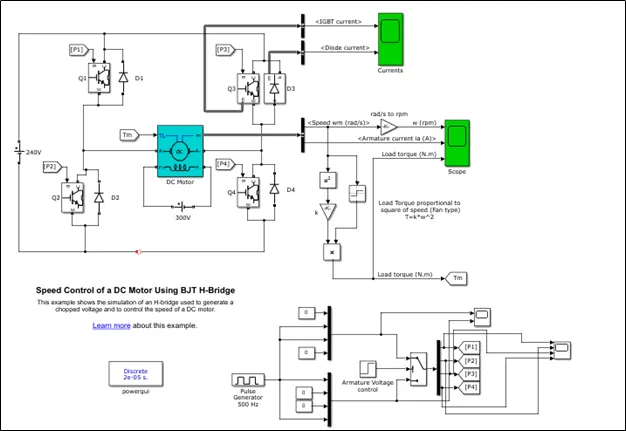
The above diagram shows the block diagram of the DC-DC chopper for the motor control, in this model it is implemented as two quadrant operation. i.e. forward motoring and reverse motoring.
Here they are using four IGBTs as the power conditioning devices, by varyinh the duty cycle we can achieve the desire operation of motor. The motor is wound-field DC machine, access is provided to the field connections so that the machine can be used as a separately excited, shunt-connected or a series-connected DC machine.
The controlling are IGVTs are done through the controlling circuit which shows at bottom of the right corner, at first motor is working as the forward motoring mode with chopper 1 & 4 are active, after 0.5 sec for reverse motoring mode IGBT 3 & 2 are operated using pulse generator.
Original Output:-
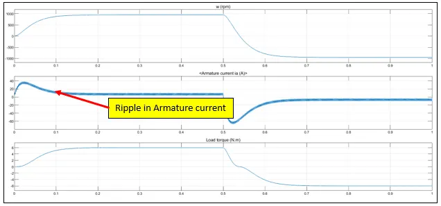
We can see in the result that there are lot of Ripple in output current. Approximate ripple is 6A in current which can cause lot of problem in smooth operation of motor.
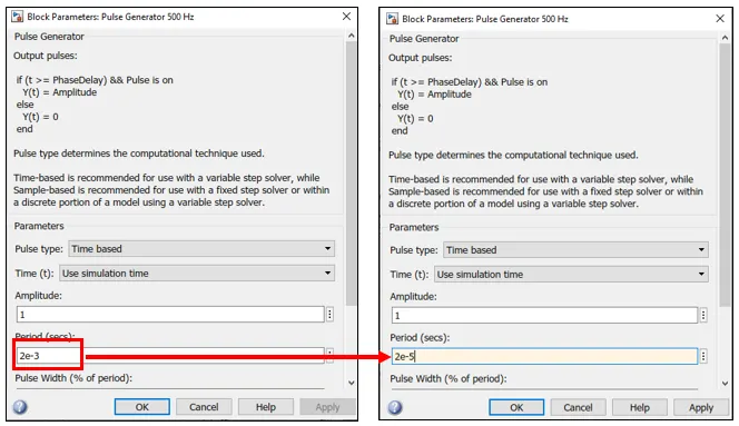
For this we can increase the operating frequency of IGBTs to reduce the ripple in current.
From 2e-3 to 2e-5.
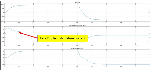
Beacause of this the ripple is reduce to nearly about 0.05A only.
2. Refer to help section of ‘The Four-Quadrant Chopper DC Drive (DC7) block’. Compare it with H-bridge model.
Ans:-
|
Parameter |
DC Drive |
DC7 |
|
Switching Frequency |
More |
less |
|
Ripple in Armature current |
Less |
More |
|
Complexity |
More |
less |
|
No. Quadrant Operations |
Two |
Four |
Compared to other DC drives, the main advantage of using the four quadrant chopper DC drive is that it can operate in all 4 quadrants. Each quadrant in its characteristics represents a different mode of operation.
The detailed circuit diagram for the DC7 block is shown below:
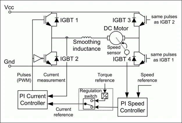
4 quadrant chopper DC drives are used mainly due to their ability to work in the 4 different quadrants of operation. It allows the controller to command the DC motor to rotate in clockwise and counter clockwise directions and to perform braking. Traditional DC motors would rely on the innate friction and air resistance forces or actual physical brakes to bring the motor to rest. The other simpler option is to switch off the motor till it comes to rest.
3. Make a suitable EV model using DC7 block and make result report.
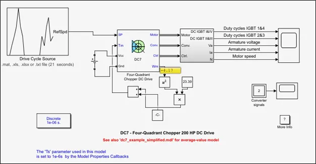
For this model of the EV, we will be using a new equation that characterizes the relation between the torque and the speed which is shown below:
T=23.39w2+0.0036
To model this equation we use the following blocks
-Product
-Square
-Add
-Constant
Also in actual model, they are using AC source, in our model we replaced it with the Battery.
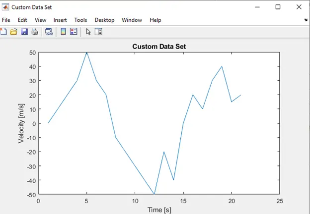
Drive Cycle:- For this exercise we create our own drive cycle. The time is varying from 0 to 20 sec, and velocity is varying from -40 to +50
Result:-
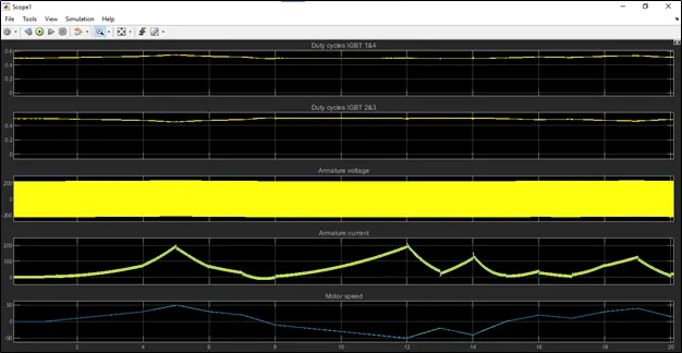
Armature Voltage:- The armature voltage will fluctuate because every time the power switch occurs between IGBT 1&4 and 2&3, the polarity of the voltage will reverse as it flows through the armature of the inductor. The armature voltage from the graph appears to be fluctuating between 200V and -200V and this is occurring at a very high frequency. When IGBT switches 1&4 are ON and switches 2&3 are OFF, the polarity of the armature voltage polarity will be positive. When IGBT switches 2&3 are ON and switches 1&4 are OFF, the armature voltage polarity will be negative. This fluctuation in polarity will continue throughout the drive cycle as the motor will operate in the forward motoring mode only since the motor is not being made to brake or rotate in the reverse direction.
Armature Current:- Initially, there is a spike in the armature current when the motor starts to work. Then, the armature current fluctuations occur very rapidly as the IGBT switches 1&4 get switched ON and OFF continuously at a very high frequency. This switching is done obviously to control the power that the motor receives to make it perform the forward motoring operation. The forward motoring operation occurs till t = 5 seconds which is when the motor angular speed is a maximum. After this, the motor angular speed decreases till the end of the drive cycle and this causes a change in the fluctuation of current. The maximum armature current and minimum armature current both decrease as the power requirement to the motor decreases when the motor angular speed decreases. The armature current follows the drive cycle data very well.
Motor Speed:- This graph is simply plotting the motor angular speeds against the time and just translates the drive cycle data in to a plot. The angular speed of the motor increases gradually from rest at t = 0 seconds to a maximum level of 50 radians per second at t = 6 seconds. It is at this point, that the maximum power is required by the motor to achieve this angular speed. From here, the motor speed steadily decreases and eventually returns to the resting state by the end of the drive cycle at t = 20 seconds.