Thermal modeling of battery pack
Aim:- For a 10 cell series lithium ion battery model, simulate the thermal effects and compare life cycle performance at various temperatures, charge & discharge rates using MATLAB.
Ans:-
Lithium iron Battery:- A lithium-ion battery or Li-ion battery is a type of rechargeable battery. Lithium-ion batteries are commonly used for portable electronics and electric vehicles and are growing in popularity for military and aerospace applications.
In the batteries, lithium ions move from the negative electrode through an electrolyte to the positive electrode during discharge, and back when charging. Li-ion batteries use an intercalated lithium compound as the material at the positive electrode and typically graphite at the negative electrode. The batteries have a high energy density, no memory effect (other than LFP cells) and low self-discharge. They can however be a safety hazard since they contain flammable electrolytes, and if damaged or incorrectly charged can lead to explosions and fires. Samsung was forced to recall Galaxy Note 7 handsets following lithium-ion fires, and there have been several incidents involving batteries on Boeing 787s.
Hence it is very useful to simulate the battery performance (Electrically and thermally) to apply before the device.
Thermal simulation of Lithium iron Battery using MATLA-SIMULINK:-
For this, we are going to use MATLAB-Simulink Model, instead of using direct battery model we are using equivalent circuit 1RC model for Lithium Mode. In this we are characterizing Battery model using Capacitor and resistor in parallel. The characteristic equations are made using Lookup table.
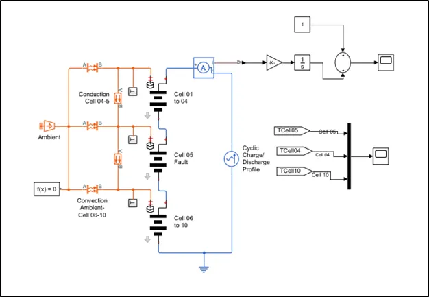
There are total 3 Main systems working In this plant.
- Electrical System
- Thermal System
- Measurement System
These systems are shows in the model also.
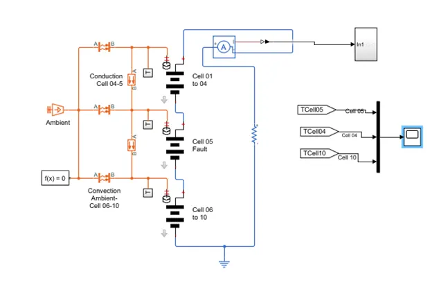
In Electrical system there are total 10 no. of cells connected In series. 1St block represents the 4 series cells connected in series which have the identical parameters (Open circuit voltage, Internal resistance, capacity). The next represent the 5th cell which have the fault, due to which it possesses the different parameters than its neighboring cell.
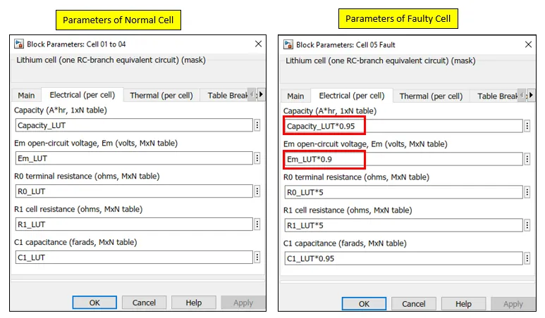
The internal characteristics of cell parameters is defined by the Lookup table, the MATLAB script file is used for this.
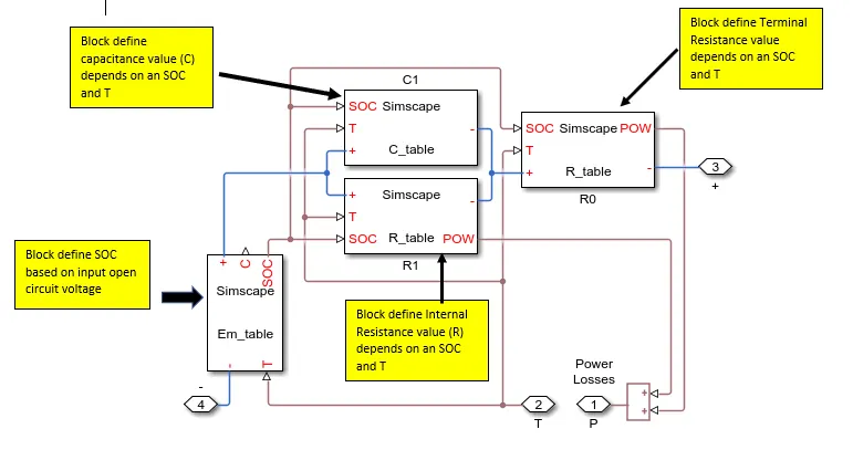
This is equivalent circuit of Lithium Iron battery represent by the parallel RC network. As we can see in the model itself there are various block for operation, basically these all blocks are run by the MATLAB script, by which they define the variable.
Thermal System: - In this system there is one ambient source which define the ambient temperature of cells, and heat is transfer to the cell through two methods, conduction & convection. Hence for these two types we have two types.
Ambient Temperature: - This is set to 293.5 K, which is equivalent of 20 C.

Conduction:-The heat transfer by direct contact of material is called by heat transfer by conduction. In our model this is type of heat which transfer by neighboring cells to each other.
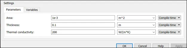
Convection:- The heat transfer not by direct contact of material is called by heat transfer by conduction. In our model this is type of heat which transfer by ambient temperature to cell body.
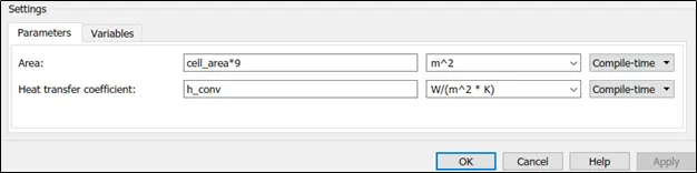
Thermal Reference: This block represents a reference point in a thermal network where the temperature is equal to absolute zero. Controlled heat ow rate source: This block represents an ideal energy source in a thermal network that can maintain a controlled heat ow rate regardless of the temperature difference. The heat ow rate is set by the physical signal port S. A positive heat ow rate flows from port A to port B. Thermal Mass: This block models internal energy storage in a thermal network. The rate of temperature increase is proportional to the heat ow rate into the material and inversely proportional to the mass and specific heat of the material.
Temperature Sensor: This block measures temperature in a thermal network. There is no heat ow through the sensor. The physical signal port T reports the temperature difference across the sensor. The measurement is positive when the temperature at port A is greater than the temperature at port B.
Simulation of Model:-
- First ambient temperature is set to 20 C, and temperature of all cell is set to be increment with Time, and at same rate at other. (Same thermal property as other cells)
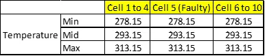
In our model Temperature characteristics are define by the Look Up table in relation with SOC, and open circuit voltage. The other parameter is unchanged as stated in above.
Result:-
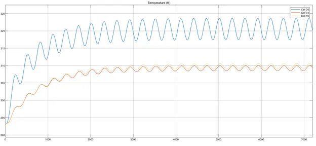
The blue color line represents the cell 5 temp. we can see the increase in temperature and more variation as cell 5 parameters are different than others. The faulty cell temperature rises to 325 Kelvin as other cell temperature is in line with each other.
Heat Conduction:-
Heat transfer by conduction
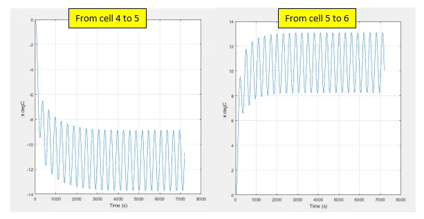
We can see clearly, as cell no. 5 is faulty, the heat is transfer by conduction to neighboring cell as it have more heat. The positive & negative temperature represent the direction o heat transfer.
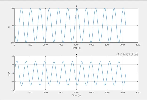
Voltage and Current of Cyclic Charger:-
SOC Calculation: -
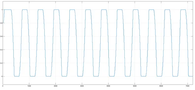
For SOC calculation we use a coulomb counting method. We assume initial State of charge is 0.75 %
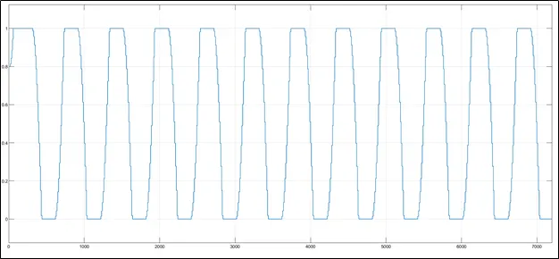
- Ambient temperature is set to 30 C, and the faulty cell temperature characteristics changes w.r.t other cells
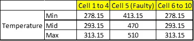
In above table we can see, the temperature chara of faulty cell, w.r.t same open circuit voltage and SOC.
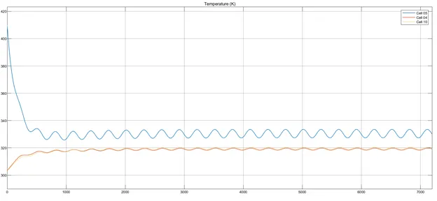
The initial temperature we set to the 400 K, as we can see to the graph, but as we change the temperature characteristics of cell 5, the maximum temperature also increases to 335 K, and for normal cell to nearly 320 K, as heat of faulty cell is transfer to neighboring cell.
Heat Conduction:-
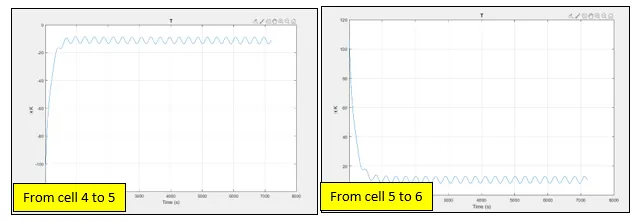
WE can see, as we set the initial temperature, the heat conduction graph starts from the 100 C, and stable at the ambient temperature we set(30 C)
SOC Calculation:-
Current & Voltage of cyclic charger:-
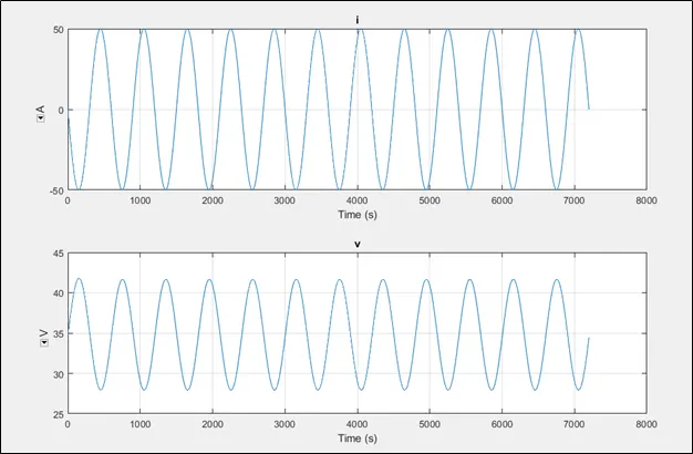
The peak amplitude of voltage is 42 V, and current is 50A.
Discharge of battery in Load:-
Now instead of cyclic charge and discharge we will only discharge our battery in Load. WE assume load hear is purely resistive and having ohmic value of 74.
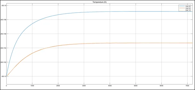
Temperature of Cell:-
As here current is steady because of resistive load, the temperature of cells increase steadily, and saturate at a point when SOC of cell in zero.
SOC of Cell:-
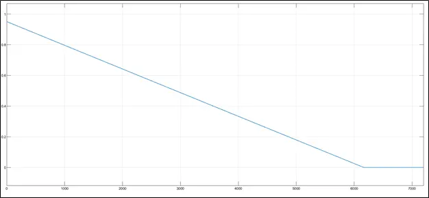
As we can see, the SOC of battery is continuously decreasing, as there is no charging available now, hence after 6170 sec. Battery is completely discharge and SOC of battery become 0.
Conclusion:-
The heat is transfer from Faulty cell to Normal cell by convection & conduction, which intern increases the temperature of other cells.
Based on temperature. The cyclic current and voltage slightly changes.
As we discharge cell at constant current, there is constant heat flow from the cell. (Heat generation is depend on variation in current flow.)